Table of Contents
Advertisement
Quick Links
This user's guide describes the characteristics, operation, and use of the TPS65217 evaluation module
(EVM). The TPS65217EVM is a fully assembled platform for evaluating the performance of the TPS65217
power management device. This document includes schematic diagrams, a printed circuit board (PCB)
layout, and bill of materials.
1
2
2.1
2.2
2.3
2.4
....................................................................................................................
3
4
5
6
.........................................................................................................................
7
......................................................................................................................
8
8.1
9
10
1
2
3
4
5
6
7
8
1
...................................................................................................................
2
......................................................................................................................
3
SLVU580B - November 2011 - Revised June 2012
Submit Documentation Feedback
..................................................................................................................
................................................................................................................
.............................................................................................................
.....................................................................................................
.......................................................................................................
..............................................................................................................
...............................................................................................
.....................................................................................................
........................................................................................................
..................................................................................
........................................................................................................
.............................................................................................................
........................................................................................................
................................................................................................
.....................................................................................................
.......................................................................................................
.....................................................................................................
........................................................................................................
...........................................................................................
.............................................................................................................
Copyright © 2011-2012, Texas Instruments Incorporated
SLVU580B - November 2011 - Revised June 2012
Contents
List of Figures
...............................................................
List of Tables
User's Guide
TPS65217 EVM
TPS65217 EVM
2
2
2
2
2
3
4
5
6
6
7
8
8
11
13
3
4
7
8
9
10
11
12
5
6
6
1
Advertisement
Table of Contents

Related Manuals for Texas Instruments TPS65217 EVM


Summary of Contents for Texas Instruments TPS65217 EVM
-
Page 1: Table Of Contents
......................Layout - Silkscreen ................... Layout - Top Layer Silkscreen List of Tables ......................Terminal Blocks ........................Test Points ........................Jumpers SLVU580B – November 2011 – Revised June 2012 TPS65217 EVM Submit Documentation Feedback Copyright © 2011–2012, Texas Instruments Incorporated... -
Page 2: Introduction
EVM via the USB-to-GPIO interface. Power Supply A DC power supply capable of delivering up to 5V and 3A is required to operate this EVM. TPS65217 EVM SLVU580B – November 2011 – Revised June 2012 Submit Documentation Feedback Copyright © 2011–2012, Texas Instruments Incorporated... -
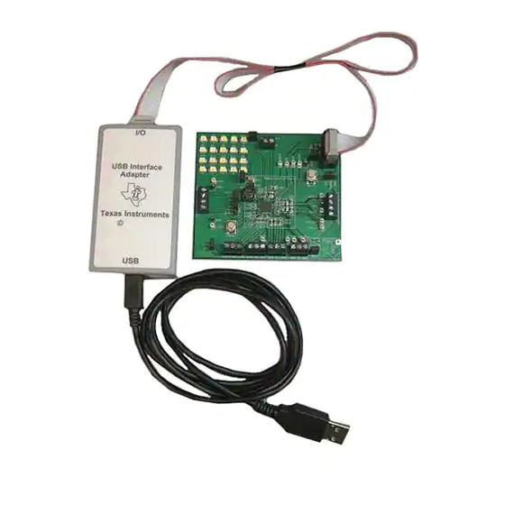
Page 3: Evm Kit
EVM Kit Figure 1 shows the EVM kit. Figure 1. TPS65217 EVM KIT NOTE: If the ribbon cable is not connected to EVM connector J8, the user must still supply 3.3V to the 3P3 node. SLVU580B – November 2011 – Revised June 2012... -
Page 4: Schematic
V3P3 GPIO3 4.7K 4.7K GPIO2 PGND 22uF 22uF PGND PGND PGND TP19 TP24 DCDC1 DCDC2 PGND Figure 2. TPS65217 EVM Schematic TPS65217 EVM SLVU580B – November 2011 – Revised June 2012 Submit Documentation Feedback Copyright © 2011–2012, Texas Instruments Incorporated... -
Page 5: Terminal Block Descriptions
LS1 / LDO3 Output Ground Ground LS2OUT LS2 / LDO4 Output I2C Data I2C Clock Ground 3.3V GPIO_PWR_EN Software PWR_EN signal SLVU580B – November 2011 – Revised June 2012 TPS65217 EVM Submit Documentation Feedback Copyright © 2011–2012, Texas Instruments Incorporated... -
Page 6: Test Point Descriptions
Connects LED string to ISINK1. Must connect to use LEDs. ISINK2 Connects LED string to ISINK2. Must connect to use LEDs. TPS65217 EVM SLVU580B – November 2011 – Revised June 2012 Submit Documentation Feedback Copyright © 2011–2012, Texas Instruments Incorporated... -
Page 7: Setup
Setup www.ti.com Setup Example setup for using TPS65217 EVM spacer spacer spacer - L oad for DCDC3+ + Voltmeter - USB-to-GPIO Computer + Power Supply - Figure 3. TPS65217 EVM Setup SLVU580B – November 2011 – Revised June 2012 TPS65217 EVM Submit Documentation Feedback Copyright ©... -
Page 8: Software
GUI. TPS65217 EVM SLVU580B – November 2011 – Revised June 2012 Submit Documentation Feedback Copyright © 2011–2012, Texas Instruments Incorporated... -
Page 9: Tps65217 Gui Basic
The software includes an auto-password function so that the protected registers may be used more easily (without entering any password). If JP9 is not installed, the GPIO tab may be used to control the PWR_EN signal. SLVU580B – November 2011 – Revised June 2012 TPS65217 EVM Submit Documentation Feedback Copyright © 2011–2012, Texas Instruments Incorporated... -
Page 10: Tps65217 Gui Gpio
Software www.ti.com Figure 6. TPS65217 GUI GPIO TPS65217 EVM SLVU580B – November 2011 – Revised June 2012 Submit Documentation Feedback Copyright © 2011–2012, Texas Instruments Incorporated... -
Page 11: Silkscreen Layouts
Silkscreen Layouts www.ti.com Silkscreen Layouts Figure 7. Layout - Silkscreen SLVU580B – November 2011 – Revised June 2012 TPS65217 EVM Submit Documentation Feedback Copyright © 2011–2012, Texas Instruments Incorporated... -
Page 12: Layout - Top Layer Silkscreen
Silkscreen Layouts www.ti.com Figure 8. Layout - Top Layer Silkscreen TPS65217 EVM SLVU580B – November 2011 – Revised June 2012 Submit Documentation Feedback Copyright © 2011–2012, Texas Instruments Incorporated... -
Page 13: Bill Of Materials
TP5, TP10, TP12, Keystone Electronics 5002 TEST POINT PC MINI 0.040"D WHITE TP13, TP14, TP16, TP19, TP24, TP26, TP27, TP28, TP29, TP45, TP46 SLVU580B – November 2011 – Revised June 2012 TPS65217 EVM Submit Documentation Feedback Copyright © 2011–2012, Texas Instruments Incorporated... - Page 14 Any exceptions to this are strictly prohibited and unauthorized by Texas Instruments unless user has obtained appropriate experimental/development licenses from local regulatory authorities, which is responsibility of user including its acceptable authorization.
- Page 15 FCC Interference Statement for Class B EVM devices This equipment has been tested and found to comply with the limits for a Class B digital device, pursuant to part 15 of the FCC Rules. These limits are designed to provide reasonable protection against harmful interference in a residential installation. This equipment generates, uses and can radiate radio frequency energy and, if not installed and used in accordance with the instructions, may cause harmful interference to radio communications.
- Page 16 Also, please do not transfer this product, unless you give the same notice above to the transferee. Please note that if you could not follow the instructions above, you will be subject to penalties of Radio Law of Japan. Texas Instruments Japan Limited (address) 24-1, Nishi-Shinjuku 6 chome, Shinjuku-ku, Tokyo, Japan http://www.tij.co.jp...
- Page 17 FDA Class III or similar classification, then you must specifically notify TI of such intent and enter into a separate Assurance and Indemnity Agreement. Mailing Address: Texas Instruments, Post Office Box 655303, Dallas, Texas 75265 Copyright © 2012, Texas Instruments Incorporated...
- Page 18 IMPORTANT NOTICE Texas Instruments Incorporated and its subsidiaries (TI) reserve the right to make corrections, modifications, enhancements, improvements, and other changes to its products and services at any time and to discontinue any product or service without notice. Customers should obtain the latest relevant information before placing orders and should verify that such information is current and complete.
- Page 19 Mouser Electronics Authorized Distributor Click to View Pricing, Inventory, Delivery & Lifecycle Information: Texas Instruments TPS65217AEVM...
Need help?
Do you have a question about the TPS65217 EVM and is the answer not in the manual?
Questions and answers