Advertisement
Quick Links
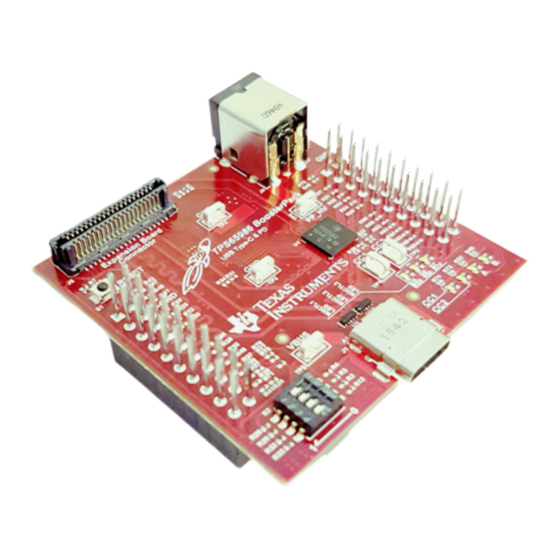
This document is the user's guide for the TPS65986 evaluation module (TPS65986EVM). The
TPS65986EVM allows for evaluation of the TPS65986 device as part of a stand-alone testing kit and for
development and testing of USB Type-C and power-delivery (PD) end products.
LaunchPad is a trademark of Texas Instruments.
All other trademarks are the property of their respective owners.
SLVUAN9A – June 2016 – Revised July 2016
Submit Documentation Feedback
TPS65986 EVM User's Guide
Copyright © 2016, Texas Instruments Incorporated
User's Guide
SLVUAN9A – June 2016 – Revised July 2016
TPS65986 EVM User's Guide
1
Advertisement

Related Manuals for Texas Instruments TPS65986EVM


Summary of Contents for Texas Instruments TPS65986EVM
- Page 1 This document is the user's guide for the TPS65986 evaluation module (TPS65986EVM). The TPS65986EVM allows for evaluation of the TPS65986 device as part of a stand-alone testing kit and for development and testing of USB Type-C and power-delivery (PD) end products.
- Page 2 TPS65986 device enables the appropriate power path and configures alternate mode settings for internal and (optional) external multiplexers. This user's guide describes the TPS65986EVM and the capabilities of the EVM with the DP-EXPANSION- EVM. This guide also contains testing procedures of various PD-power and alternate mode configurations.
- Page 3 2. When switched to the right position, the TPS65986EVM changes the configuration to prefer USB3.0 Multifunction and renegotiates the DisplayPort alternate mode. When switched back to the left position, the TPS65986EVM changes the configuration to not prefer USB3.0 Multifunction and renegotiates the DisplayPort alternate mode.
- Page 4 5.1.3.1 Barrel Jack Detect The TPS65986EVM is capable of requesting a power-role swap when the barrel jack is connected on an EVM that is currently bus powered which is valid for the configuration IDs that are capable of delivering power. The barrel jack voltage is sensed by a comparator, which drives GPIO2 on the TPS65986 device.
-
Page 5: Led Indicators Description
TPS6598x Configuration Tool, the voltage of PP_HV can be set to a minimum of 12 V for high- voltage contracts. The pre-loaded TPS65986EVM firmware expects to have 20 V at PP_HV (or on barrel jack) for the configured power capabilities. The PP_HV test point can also be used to sink power when acting as a consumer or a bus powered device. -
Page 6: Firmware Configurations
4-lane DP after the configuration in the table has been loaded. Table 2 lists the eight configurations on the EVM. Figure 3. S2 Switch Board TPS65986 EVM User's Guide SLVUAN9A – June 2016 – Revised July 2016 Submit Documentation Feedback Copyright © 2016, Texas Instruments Incorporated... - Page 7 Using the TPS65986EVM www.ti.com Table 2. TPS65986EVM Configuration Table Type-C PD Sink Port Type PD Source PD Control Response PD Control Power Capabilities Switch S1 DP Support Application FET Paths Used V at V at V at V at V at...
- Page 8 The DP-EXPANSION-EVM (DisplayPort source board) allows the user to use the USB and DisplayPort signals into a legacy notebook. TPS65986 EVM User's Guide SLVUAN9A – June 2016 – Revised July 2016 Submit Documentation Feedback Copyright © 2016, Texas Instruments Incorporated...
- Page 9 This configuration is a UFP in terms of data for USB data only. The DP-EXPANSION-EVM( DisplayPort source board) can be used to bring out the USB signals. SLVUAN9A – June 2016 – Revised July 2016 TPS65986 EVM User's Guide Submit Documentation Feedback Copyright © 2016, Texas Instruments Incorporated...
- Page 10 UFP_D products are connected. The ideal connections are to a DFP_D DisplayPort product or a USB host. The DP-EXPANSION-EVM (DisplayPort sink board) can be used to bring out the USB and DisplayPort signals. TPS65986 EVM User's Guide SLVUAN9A – June 2016 – Revised July 2016 Submit Documentation Feedback Copyright © 2016, Texas Instruments Incorporated...
- Page 11 This configuration is a UFP in terms of data for USB only. The DP-EXPANSION-EVM (DisplayPort sink board) can be used to route the USB signals. SLVUAN9A – June 2016 – Revised July 2016 TPS65986 EVM User's Guide Submit Documentation Feedback Copyright © 2016, Texas Instruments Incorporated...
- Page 12 The TPS65986 device cannot act as a host but can pass the USB connection to a host by using the DP-EXPANSION-EVM (DisplayPort source board). Figure 5 shows how the notebook, DP-EXPANSION- EVM, TPS65986EVM, cable, and flash drive are connected Notebook (DP and USB Source)
- Page 13 DP SInk USB Sink DP-EXPANSION- (Sink) Type-C Notebook (MacBook/ Type-C Cable TPS65986-EVM ChromeBook) Figure 8. Connecting EVM to Type-C Host SLVUAN9A – June 2016 – Revised July 2016 TPS65986 EVM User's Guide Submit Documentation Feedback Copyright © 2016, Texas Instruments Incorporated...
- Page 14 DisplayPort functionality with two TPS65986EVMs and the DP-EXPANSION-EVM (DIsplayPort source and sink boards). CAUTION Do not connect the DP-EXPANSION-EVM to the TPS65986EVM when the barrel jack is connected—this may result in a short if the J5 expansion board connectors are misaligned.
- Page 15 – Dual Role Port → DFP – DFP → UFP • Verify that VBUS is reaching 5 V when connected (see Figure SLVUAN9A – June 2016 – Revised July 2016 TPS65986 EVM User's Guide Submit Documentation Feedback Copyright © 2016, Texas Instruments Incorporated...
- Page 16 Check for a small spike during a cable attach event to verify that the 5-V switch is closed and is opened once the overcurrent event is detected. Figure 11. Type-C Connection and PD Negotiation TPS65986 EVM User's Guide SLVUAN9A – June 2016 – Revised July 2016 Submit Documentation Feedback Copyright © 2016, Texas Instruments Incorporated...
- Page 17 SPI Master and firmware data is written to the TPS65986 using I Connecting the TPS65986EVM to the Aardvark SPI Pins with Jumper Wires Wire the Aardvark SPI pins to the corresponding SPI pins on the TPS65986EVM J2 and J3 headers as shown in Figure 12.
- Page 18 Use the following steps to load the EVM firmware: Step 1. Click the SPI FW Update link on the left side of the GUI (see Figure 15). TPS65986 EVM User's Guide SLVUAN9A – June 2016 – Revised July 2016 Submit Documentation Feedback Copyright © 2016, Texas Instruments Incorporated...
- Page 19 Programming the TPS65986EVM Firmware www.ti.com Figure 15. SPI Firmware Update Screen Step 2. Choose the TPS65986EVM firmware image to load by clicking on the Choose File button (see Figure 16). Select the appropriate EVM image (2 region binary file) in the window and verify that it is 191 KB in size.
- Page 20 Figure 19. SPI Firmware Update—Firmware Update Complete Step 6. Press the RESET button (S1) on the top-left side of the TPS65986EVM. Pressing this button causes the EVM to load the new firmware from flash. Failure to press the Reset button will...
- Page 21 Step 8. Verify the that the MODE register reads APP (see Figure 21). Figure 21. Mode Register TPS65986EVM Schematic Figure 22 shows the block diagram of the main components of the TPS65986EVM. The main schematic blocks are the processor (Figure 23), power path (Figure 24), power supply...
- Page 22 C_SSTX2_P C_SST X2_P C_SSTX2_P C_SSTX2_N C_SST X2_N C_SSTX2_N Copyright © 2016, Texas Instruments Incorporated Figure 22. TPS65986EVM Block Diagram TPS65986 EVM User's Guide SLVUAN9A – June 2016 – Revised July 2016 Submit Documentation Feedback Copyright © 2016, Texas Instruments Incorporated...
- Page 23 LDO_3V3 3.83k I2C_SCL1 3.83k I2C_SDA1 10.0k I2C_IRQ1Z TPS65986ABZQZR Copyright © 2016, Texas Instruments Incorporated Figure 23. TPS65986EVM Processor Block SLVUAN9A – June 2016 – Revised July 2016 TPS65986 EVM User's Guide Submit Documentation Feedback Copyright © 2016, Texas Instruments Incorporated...
- Page 24 LDO_1V8A 1µF LDO_1V8A LDO_1V8D 1µF LDO_1V8D TPS65986ABZQZR Copyright © 2016, Texas Instruments Incorporated Figure 24. TPS65986EVM Power Path Block TPS65986 EVM User's Guide SLVUAN9A – June 2016 – Revised July 2016 Submit Documentation Feedback Copyright © 2016, Texas Instruments Incorporated...
- Page 25 Max 1100mA 32.4k Typ 900mA Min 700mA TPS2500DRCR Copyright © 2016, Texas Instruments Incorporated Figure 25. TPS65986EVM Power Supply Block SLVUAN9A – June 2016 – Revised July 2016 TPS65986 EVM User's Guide Submit Documentation Feedback Copyright © 2016, Texas Instruments Incorporated...
- Page 26 White 1.00k 1.00k 1.00k MUX_CTL_3 CC2_LED CC1_LED Copyright © 2016, Texas Instruments Incorporated Figure 26. TPS65986EVM LED Indicators Block TPS65986 EVM User's Guide SLVUAN9A – June 2016 – Revised July 2016 Submit Documentation Feedback Copyright © 2016, Texas Instruments Incorporated...
- Page 27 RX2+ TX2+ C_SSTX2_P 20-0000016-01 Feedthrough Feedthrough TPD4E05U06DQAR TPD4E05U06DQAR Copyright © 2016, Texas Instruments Incorporated Figure 27. TPS65986EVM Type-C Block SLVUAN9A – June 2016 – Revised July 2016 TPS65986 EVM User's Guide Submit Documentation Feedback Copyright © 2016, Texas Instruments Incorporated...
- Page 28 USB_5V C_SSRX C_SSRX1_N C_SSRX C_SSRX1_P P3V3 LSEM-120-03.0-F-DV-A-N-K-TR Copyright © 2016, Texas Instruments Incorporated Figure 28. TPS65986EVM Inter PCB Block TPS65986 EVM User's Guide SLVUAN9A – June 2016 – Revised July 2016 Submit Documentation Feedback Copyright © 2016, Texas Instruments Incorporated...
- Page 29 SPI_SSZ BP_USB2_RP_P BP_RP_P BP_RP_N BP_USB2_RP_N USB_RP_P USB_RP_N Copyright © 2016, Texas Instruments Incorporated Figure 29. TPS65986EVM Booster Connector Block SLVUAN9A – June 2016 – Revised July 2016 TPS65986 EVM User's Guide Submit Documentation Feedback Copyright © 2016, Texas Instruments Incorporated...
- Page 30 TPS65986EVM Board Layout www.ti.com TPS65986EVM Board Layout The following figures contain the PCB layouts of the TPS65986EVM. Figure 30. TPS65986EVM Top Layer Figure 31. TPS65986EVM Top Layer Component View Figure 32. TPS65986EVM GND Plane 1 Figure 33. TPS65986EVM Mid Layer 1 TPS65986 EVM User's Guide SLVUAN9A –...
- Page 31 TPS65986EVM Board Layout www.ti.com Figure 34. TPS65986EVM GND Plane 2 Figure 35. TPS65986EVM Mid Layer 2 Figure 36. TPS65986EVM Mid Layer 3 Figure 37. TPS65986EVM GND Plane 3 SLVUAN9A – June 2016 – Revised July 2016 TPS65986 EVM User's Guide Submit Documentation Feedback Copyright ©...
- Page 32 TPS65986EVM Board Layout www.ti.com Figure 38. TPS65986EVM Bottom Layer Figure 39. TPS65986EVM Bottom Layer Component View TPS65986 EVM User's Guide SLVUAN9A – June 2016 – Revised July 2016 Submit Documentation Feedback Copyright © 2016, Texas Instruments Incorporated...
- Page 33 TPS65986EVM Bill of Materials www.ti.com TPS65986EVM Bill of Materials Table 12 list the bill of materials (BOM) for the TPS65986EVM. Table 12. BOM Package Alternate Part Alternate Designator Quantity Value Description Part Number Manufacturer Reference Number Manufacturer !PCB1 Printed Circuit Board...
- Page 34 RES, 8.45 k, 1%, 0.063 W, 0402 0402 CRCW04028K45FKED Vishay-Dale 47.5k RES, 47.5 k, 1%, 0.063 W, 0402 0402 CRCW040247K5FKED Vishay-Dale TPS65986 EVM User's Guide SLVUAN9A – June 2016 – Revised July 2016 Submit Documentation Feedback Copyright © 2016, Texas Instruments Incorporated...
- Page 35 RES, 39 k, 5%, 0.063 W, 0402 0402 CRCW040239K0JNED Vishay-Dale 560k RES, 560 k, 5%, 0.063 W, 0402 0402 CRCW0402560KJNED Vishay-Dale SLVUAN9A – June 2016 – Revised July 2016 TPS65986 EVM User's Guide Submit Documentation Feedback Copyright © 2016, Texas Instruments Incorporated...
-
Page 36: Revision History
Changes from Original (June 2016) to A Revision ......................Page ........ • Deleted references to USB2MANY board and replaced with Aardvark or FTDI-based adapter Revision History SLVUAN9A – June 2016 – Revised July 2016 Submit Documentation Feedback Copyright © 2016, Texas Instruments Incorporated... - Page 37 STANDARD TERMS AND CONDITIONS FOR EVALUATION MODULES Delivery: TI delivers TI evaluation boards, kits, or modules, including any accompanying demonstration software, components, or documentation (collectively, an “EVM” or “EVMs”) to the User (“User”) in accordance with the terms and conditions set forth herein. Acceptance of the EVM is expressly subject to the following terms and conditions.
- Page 38 FCC Interference Statement for Class B EVM devices NOTE: This equipment has been tested and found to comply with the limits for a Class B digital device, pursuant to part 15 of the FCC Rules. These limits are designed to provide reasonable protection against harmful interference in a residential installation.
- Page 39 【無線電波を送信する製品の開発キットをお使いになる際の注意事項】 開発キットの中には技術基準適合証明を受けて いないものがあります。 技術適合証明を受けていないもののご使用に際しては、電波法遵守のため、以下のいずれかの 措置を取っていただく必要がありますのでご注意ください。 1. 電波法施行規則第6条第1項第1号に基づく平成18年3月28日総務省告示第173号で定められた電波暗室等の試験設備でご使用 いただく。 2. 実験局の免許を取得後ご使用いただく。 3. 技術基準適合証明を取得後ご使用いただく。 なお、本製品は、上記の「ご使用にあたっての注意」を譲渡先、移転先に通知しない限り、譲渡、移転できないものとします。 上記を遵守頂けない場合は、電波法の罰則が適用される可能性があることをご留意ください。 日本テキサス・イ ンスツルメンツ株式会社 東京都新宿区西新宿6丁目24番1号 西新宿三井ビル 3.3.3 Notice for EVMs for Power Line Communication: Please see http://www.tij.co.jp/lsds/ti_ja/general/eStore/notice_02.page 電力線搬送波通信についての開発キットをお使いになる際の注意事項については、次のところをご覧くださ い。http://www.tij.co.jp/lsds/ti_ja/general/eStore/notice_02.page SPACER EVM Use Restrictions and Warnings: 4.1 EVMS ARE NOT FOR USE IN FUNCTIONAL SAFETY AND/OR SAFETY CRITICAL EVALUATIONS, INCLUDING BUT NOT LIMITED TO EVALUATIONS OF LIFE SUPPORT APPLICATIONS.
- Page 40 Notwithstanding the foregoing, any judgment may be enforced in any United States or foreign court, and TI may seek injunctive relief in any United States or foreign court. Mailing Address: Texas Instruments, Post Office Box 655303, Dallas, Texas 75265 Copyright © 2015, Texas Instruments Incorporated...
-
Page 41: Important Notice
IMPORTANT NOTICE Texas Instruments Incorporated and its subsidiaries (TI) reserve the right to make corrections, enhancements, improvements and other changes to its semiconductor products and services per JESD46, latest issue, and to discontinue any product or service per JESD48, latest issue. -
Page 42: Texas Instruments
Mouser Electronics Authorized Distributor Click to View Pricing, Inventory, Delivery & Lifecycle Information: Texas Instruments TPS65986EVM...
Need help?
Do you have a question about the TPS65986EVM and is the answer not in the manual?
Questions and answers