Table of Contents
Advertisement
Quick Links
www.ti.com
User's Guide
TPS6594x-Q1 Evaluation Module
The TPS6594x-Q1 and TPS6593x-Q1 evaluation modules (EVM) highlight the performance and flexibility of the
TPS6594x-Q1 and TPS6593x-Q1 power management ICs (PMICs). The modular design allows the EVMs to be
stacked, which provides a multi-PMIC solution and increases the scalability of these EVMs to develop and
evaluate a wide range of power applications. The scalability of the products supports up to six devices, with one
primary and up to five secondary PMICs. This document enumerates the features and interfaces provided to
develop and evaluate the PMIC.
1
Introduction.............................................................................................................................................................................3
Started........................................................................................................................................................................3
2.1 Getting Started: Single EVM..............................................................................................................................................
2.2 Getting Started: Multiple EVM Evaluation..........................................................................................................................
2.3 The GUI Tool......................................................................................................................................................................
3 EVM Details.............................................................................................................................................................................
3.2 Terminal Blocks..................................................................................................................................................................
Descriptions.......................................................................................................................................................7
3.4 Configuration Headers.......................................................................................................................................................
Headers...................................................................................................................................................................9
Headers............................................................................................................................................................10
3.7
Connectors.......................................................................................................................................................................13
4 Customization.......................................................................................................................................................................
4.2 Changing the Phase Configuration..................................................................................................................................
5 Schematic, Layout, and Bill of Materials............................................................................................................................
Resources...........................................................................................................................................................37
7 Revision History...................................................................................................................................................................
Figure 2-1. TPS6594EVM Top View............................................................................................................................................
Figure 2-2. TPS6593EVM Top View............................................................................................................................................
Figure 3-1. TPS6594EVM Header J7..........................................................................................................................................
Figure 3-2. TPS6593EVM Header J7..........................................................................................................................................
LDO_Headers_v2....................................................................................................................................................10
Figure 4-1. TPS6594EVM Interface Settings for Communication.............................................................................................
Figure 4-2. TPS6593EVM Interface Settings for Communication.............................................................................................
Figure 4-3. Phase Configuration Components..........................................................................................................................
SLVUBT0A - JUNE 2020 - REVISED JANUARY 2021
Submit Document Feedback
ABSTRACT
Warning Warning Hot surface.
Contact may cause burns.
Do not touch!
Table of Contents
TPS6593EVM........................................................................................6
Regulators...............................................................................................................13
Interface...........................................................................................................................13
List of Figures
Configuration...........................................................................................................................11
2....................................................................................................................................11
Copyright © 2021 Texas Instruments Incorporated
configuration..................................................12
1.................................................................................17
2.................................................................................18
1.................................................................................19
TPS6594x-Q1 Evaluation Module
Table of Contents
5
5
5
5
6
7
13
16
17
37
4
4
7
8
14
15
16
1
Advertisement
Table of Contents

Related Manuals for Texas Instruments TPS6594x-Q1


Summary of Contents for Texas Instruments TPS6594x-Q1
-
Page 1: Table Of Contents
The TPS6594x-Q1 and TPS6593x-Q1 evaluation modules (EVM) highlight the performance and flexibility of the TPS6594x-Q1 and TPS6593x-Q1 power management ICs (PMICs). The modular design allows the EVMs to be stacked, which provides a multi-PMIC solution and increases the scalability of these EVMs to develop and evaluate a wide range of power applications. - Page 2 Table 5-2. TPS6593EVM Bill of Materials of Balance of Components..................Trademarks All trademarks are the property of their respective owners. TPS6594x-Q1 Evaluation Module SLVUBT0A – JUNE 2020 – REVISED JANUARY 2021 Submit Document Feedback Copyright © 2021 Texas Instruments Incorporated...
-
Page 3: Introduction
The remainder of this document describes the different connectors and jumpers available on the EVMs. Figure 2-1 Figure 2-2 shows the TPS6594EVM and the TPS6593EVM respectively. SLVUBT0A – JUNE 2020 – REVISED JANUARY 2021 TPS6594x-Q1 Evaluation Module Submit Document Feedback Copyright © 2021 Texas Instruments Incorporated... -
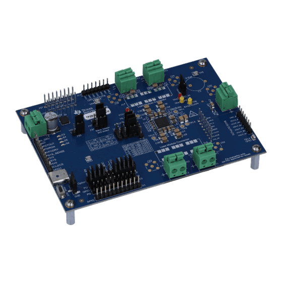
Page 4: Figure 2-1. Tps6594Evm Top View
Getting Started www.ti.com Figure 2-1. TPS6594EVM Top View Figure 2-2. TPS6593EVM Top View TPS6594x-Q1 Evaluation Module SLVUBT0A – JUNE 2020 – REVISED JANUARY 2021 Submit Document Feedback Copyright © 2021 Texas Instruments Incorporated... -
Page 5: Getting Started: Single Evm
J6 terminals. 2.3 The GUI Tool Texas Instruments provides a GUI tool to enable, configure, and evaluate the various features of the TPS6594x- Q1 with the EVM. Please refer to the GUI User's Guide SLVUBT8 for a more detailed description of this tool. -
Page 6: Differences Between The Tps6594Evm And The Tps6593Evm
Buck 5 Output, 2 A Capable Section 3.5 for applying input voltages other than VSYS to the LDO regulators through J21 TPS6594x-Q1 Evaluation Module SLVUBT0A – JUNE 2020 – REVISED JANUARY 2021 Submit Document Feedback Copyright © 2021 Texas Instruments Incorporated... -
Page 7: Test Point Descriptions
J15, which allows VSYS to be powered from the USB connection and the configuration of GPIO1. Figure 3-1. TPS6594EVM Header J7 SLVUBT0A – JUNE 2020 – REVISED JANUARY 2021 TPS6594x-Q1 Evaluation Module Submit Document Feedback Copyright © 2021 Texas Instruments Incorporated... -
Page 8: Figure 3-2. Tps6593Evm Header J7
Alternative function to support the watchdog trigger input signal. GPIO11 from the PMIC is connected to the MCU output PK4, TRIG_WDG. TPS6594x-Q1 Evaluation Module SLVUBT0A – JUNE 2020 – REVISED JANUARY 2021 Submit Document Feedback Copyright © 2021 Texas Instruments Incorporated... -
Page 9: Signal Headers
An external power supply for the LDOs can also be applied directly to J21. SLVUBT0A – JUNE 2020 – REVISED JANUARY 2021 TPS6594x-Q1 Evaluation Module Submit Document Feedback Copyright © 2021 Texas Instruments Incorporated... -
Page 10: Stack-Up Headers
J28. Communication between the boards is shared on header J29. This header, J29, is marked on the bottom silkscreen, as shown in Figure 3-5. TPS6594x-Q1 Evaluation Module SLVUBT0A – JUNE 2020 – REVISED JANUARY 2021 Submit Document Feedback Copyright © 2021 Texas Instruments Incorporated... -
Page 11: Figure 3-4. Evm Masters Slave Configuration
EVM Details Figure 3-4. EVM Masters Slave Configuration Figure 3-5. EVM Bottom View Version 2 SLVUBT0A – JUNE 2020 – REVISED JANUARY 2021 TPS6594x-Q1 Evaluation Module Submit Document Feedback Copyright © 2021 Texas Instruments Incorporated... -
Page 12: Figure 3-6. Header J37 Master And Slave Select Table Description For 'Open' Configuration
The default position for J45 is with pins 1-2 closed so that the pullup is applied to nPWRON/ENABLE. J45 is provided so that the signal nPWRON/ENABLE can be pulled low or sourced from an off board signal. TPS6594x-Q1 Evaluation Module SLVUBT0A – JUNE 2020 – REVISED JANUARY 2021 Submit Document Feedback Copyright © 2021 Texas Instruments Incorporated... -
Page 13: Connectors
J8 and J9, as shown in Figure 4-1 Figure 4-2. Alternatively these GPIOs can be used to support SPI communication. SLVUBT0A – JUNE 2020 – REVISED JANUARY 2021 TPS6594x-Q1 Evaluation Module Submit Document Feedback Copyright © 2021 Texas Instruments Incorporated... -
Page 14: Figure 4-1. Tps6594Evm Interface Settings For Communication
Customization www.ti.com Figure 4-1. TPS6594EVM Interface Settings for Communication TPS6594x-Q1 Evaluation Module SLVUBT0A – JUNE 2020 – REVISED JANUARY 2021 Submit Document Feedback Copyright © 2021 Texas Instruments Incorporated... -
Page 15: Figure 4-2. Tps6593Evm Interface Settings For Communication
For SPI communication it is recommended to remove the pullups or pulldowns on GPIO1 and GPIO2. Remove any jumpers between J8, J9, and J10 for GPIO1 and GPIO2. SLVUBT0A – JUNE 2020 – REVISED JANUARY 2021 TPS6594x-Q1 Evaluation Module Submit Document Feedback Copyright © 2021 Texas Instruments Incorporated... -
Page 16: Changing The Phase Configuration
If the voltage monitors associated with BUCK3 and BUCK4 are disabled, then it is recommended to connect the FB_Bn pins to reference ground, using R4 and R6. Figure 4-3. Phase Configuration Components TPS6594x-Q1 Evaluation Module SLVUBT0A – JUNE 2020 – REVISED JANUARY 2021 Submit Document Feedback Copyright © 2021 Texas Instruments Incorporated... -
Page 17: Schematic, Layout, And Bill Of Materials
PGND 2.2uF 2.2uF 2.2uF GNDS PGND VCCA_S PGND ENABLE GNDS SYNC GNDS Figure 5-1. TPS6594EVM 1+1+1+1+1 Configuration, Schematic Page 1 SLVUBT0A – JUNE 2020 – REVISED JANUARY 2021 TPS6594x-Q1 Evaluation Module Submit Document Feedback Copyright © 2021 Texas Instruments Incorporated... -
Page 18: Figure 5-2. Tps6594Evm 1+1+1+1+1 Configuration, Schematic
SCL2 COM4 SCL2/CS 1.0k MCUVCC SPI_CS blue VIO_IN nPWRON 1.2k SPI_EN SPI_EN Figure 5-2. TPS6594EVM 1+1+1+1+1 Configuration, Schematic Page 2 TPS6594x-Q1 Evaluation Module SLVUBT0A – JUNE 2020 – REVISED JANUARY 2021 Submit Document Feedback Copyright © 2021 Texas Instruments Incorporated... -
Page 19: Figure 5-3. Tps6593Evm 1+1+1+1+1 Configuration, Schematic
PGND 2.2uF 2.2uF 2.2uF GNDS VCCA_S PGND PGND ENABLE GNDS SYNC GNDS Figure 5-3. TPS6593EVM 1+1+1+1+1 Configuration, Schematic Page 1 SLVUBT0A – JUNE 2020 – REVISED JANUARY 2021 TPS6594x-Q1 Evaluation Module Submit Document Feedback Copyright © 2021 Texas Instruments Incorporated... -
Page 20: Figure 5-4. Tps6593Evm 1+1+1+1+1 Configuration, Schematic
SCL2 COM4 SCL2/CS 1.0k MCUVCC SPI_CS blue VIO_IN nPWRON 1.2k SPI_EN SPI_EN Figure 5-4. TPS6593EVM 1+1+1+1+1 Configuration, Schematic Page 2 TPS6594x-Q1 Evaluation Module SLVUBT0A – JUNE 2020 – REVISED JANUARY 2021 Submit Document Feedback Copyright © 2021 Texas Instruments Incorporated... -
Page 21: Figure 5-5. Layout Top, Layer 1
Schematic, Layout, and Bill of Materials Figure 5-5. Layout Top, Layer 1 SLVUBT0A – JUNE 2020 – REVISED JANUARY 2021 TPS6594x-Q1 Evaluation Module Submit Document Feedback Copyright © 2021 Texas Instruments Incorporated... -
Page 22: Figure 5-6. Layout Ground, Layer 2
Schematic, Layout, and Bill of Materials www.ti.com Figure 5-6. Layout Ground, Layer 2 TPS6594x-Q1 Evaluation Module SLVUBT0A – JUNE 2020 – REVISED JANUARY 2021 Submit Document Feedback Copyright © 2021 Texas Instruments Incorporated... -
Page 23: Figure 5-7. Layout Signal, Layer 3
Schematic, Layout, and Bill of Materials Figure 5-7. Layout Signal, Layer 3 SLVUBT0A – JUNE 2020 – REVISED JANUARY 2021 TPS6594x-Q1 Evaluation Module Submit Document Feedback Copyright © 2021 Texas Instruments Incorporated... -
Page 24: Figure 5-8. Layout Signal, Layer 4
Schematic, Layout, and Bill of Materials www.ti.com Figure 5-8. Layout Signal, Layer 4 TPS6594x-Q1 Evaluation Module SLVUBT0A – JUNE 2020 – REVISED JANUARY 2021 Submit Document Feedback Copyright © 2021 Texas Instruments Incorporated... -
Page 25: Figure 5-9. Layout Ground, Layer 5
Schematic, Layout, and Bill of Materials Figure 5-9. Layout Ground, Layer 5 SLVUBT0A – JUNE 2020 – REVISED JANUARY 2021 TPS6594x-Q1 Evaluation Module Submit Document Feedback Copyright © 2021 Texas Instruments Incorporated... -
Page 26: Figure 5-10. Layout Bottom
Schematic, Layout, and Bill of Materials www.ti.com Figure 5-10. Layout Bottom TPS6594x-Q1 Evaluation Module SLVUBT0A – JUNE 2020 – REVISED JANUARY 2021 Submit Document Feedback Copyright © 2021 Texas Instruments Incorporated... -
Page 27: Table 5-1. Tps6594Evm Bill Of Materials Of Balance Of Components
LB Q39G-L2N2-35-1 H1, H2, H3, H4 MACHINE SCREW PAN 9900 PHILLIPS 4-40 USB A MALE TO USB C Male 3021090-01M SLVUBT0A – JUNE 2020 – REVISED JANUARY 2021 TPS6594x-Q1 Evaluation Module Submit Document Feedback Copyright © 2021 Texas Instruments Incorporated... - Page 28 AEC-Q200 Grade 0, 0402 R32, R45, R51, R54 RES, 100, 5%, 0.063 W, AEC- 0402 CRCW0402100RJNED Q200 Grade 0, 0402 TPS6594x-Q1 Evaluation Module SLVUBT0A – JUNE 2020 – REVISED JANUARY 2021 Submit Document Feedback Copyright © 2021 Texas Instruments Incorporated...
- Page 29 ±15 kV ESD Protection Array for High-Speed Data Interfaces, RSE0008A (UQFN-8) 4-Channel USB ESD Solution DRY0006A TPD4S012DRYR with Power Clamp, DRY0006A (USON-6) SLVUBT0A – JUNE 2020 – REVISED JANUARY 2021 TPS6594x-Q1 Evaluation Module Submit Document Feedback Copyright © 2021 Texas Instruments Incorporated...
- Page 30 J23, J24, J25 JUMPER TIN SMD 6.85x0.97x2.51 mm S1911-46R Header (Shrouded), 1.27mm, Header(Shrouded), 1.27mm, FTSH-105-01-F-DV-K 5x2, Gold, SMT 5x2, SMT TPS6594x-Q1 Evaluation Module SLVUBT0A – JUNE 2020 – REVISED JANUARY 2021 Submit Document Feedback Copyright © 2021 Texas Instruments Incorporated...
- Page 31 RES, 0.002, 2%, 1 W, 0508 0508 KRL2012E-M-R002-G-T5 TP9, TP10, TP11, TP12, TP13 0 Test Point, Miniature, Yellow, Yellow Miniature Testpoint 5004 SLVUBT0A – JUNE 2020 – REVISED JANUARY 2021 TPS6594x-Q1 Evaluation Module Submit Document Feedback Copyright © 2021 Texas Instruments Incorporated...
-
Page 32: Table 5-2. Tps6593Evm Bill Of Materials Of Balance Of Components
MACHINE SCREW PAN 9900 PHILLIPS 4-40 USB A MALE TO USB C Male 3021090-01M H6, H7, H8, H9 SPACER FC2058-440-A TPS6594x-Q1 Evaluation Module SLVUBT0A – JUNE 2020 – REVISED JANUARY 2021 Submit Document Feedback Copyright © 2021 Texas Instruments Incorporated... - Page 33 Q200 Grade 0, 0402 R41, R43, R52 4.87 k RES, 4.87 k, 1%, 0.063 W, 0402 CRCW04024K87FKED AEC-Q200 Grade 0, 0402 SLVUBT0A – JUNE 2020 – REVISED JANUARY 2021 TPS6594x-Q1 Evaluation Module Submit Document Feedback Copyright © 2021 Texas Instruments Incorporated...
- Page 34 Power Clamp, DRY0006A (USON-6) U6, U13 Automotive Catalog, Dual, 200 DSE0006A TLV7103318QDSERQ1 mA, Low-IQ Low-Dropout Regulator for Portable Devices, DSE0006A (WSON-6) TPS6594x-Q1 Evaluation Module SLVUBT0A – JUNE 2020 – REVISED JANUARY 2021 Submit Document Feedback Copyright © 2021 Texas Instruments Incorporated...
- Page 35 6.85 × 0.97 × 2.51 mm S1911-46R Header (Shrouded), 1.27 mm, Header(Shrouded), 1.27 mm, FTSH-105-01-F-DV-K 5 × 2, Gold, SMT 5 × 2, SMT SLVUBT0A – JUNE 2020 – REVISED JANUARY 2021 TPS6594x-Q1 Evaluation Module Submit Document Feedback Copyright © 2021 Texas Instruments Incorporated...
- Page 36 0402 CRCW04021K20JNED AEC-Q200 Grade 0, 0402 TP9, TP10, TP11, TP12, TP13 0 Test Point, Miniature, Yellow, Yellow Miniature Testpoint 5004 TPS6594x-Q1 Evaluation Module SLVUBT0A – JUNE 2020 – REVISED JANUARY 2021 Submit Document Feedback Copyright © 2021 Texas Instruments Incorporated...
-
Page 37: Additional Resources
Added the TPS6594EVM and TPS6593EVM Interface Settings for Communication figure......13 • Removed the Interface Settings for SPI Communication figure............... • Updated the Phase Configuration Components figure..................SLVUBT0A – JUNE 2020 – REVISED JANUARY 2021 TPS6594x-Q1 Evaluation Module Submit Document Feedback Copyright © 2021 Texas Instruments Incorporated... - Page 38 STANDARD TERMS FOR EVALUATION MODULES Delivery: TI delivers TI evaluation boards, kits, or modules, including any accompanying demonstration software, components, and/or documentation which may be provided together or separately (collectively, an “EVM” or “EVMs”) to the User (“User”) in accordance with the terms set forth herein.
- Page 39 www.ti.com Regulatory Notices: 3.1 United States 3.1.1 Notice applicable to EVMs not FCC-Approved: FCC NOTICE: This kit is designed to allow product developers to evaluate electronic components, circuitry, or software associated with the kit to determine whether to incorporate such items in a finished product and software developers to write software applications for use with the end product.
- Page 40 www.ti.com Concernant les EVMs avec antennes détachables Conformément à la réglementation d'Industrie Canada, le présent émetteur radio peut fonctionner avec une antenne d'un type et d'un gain maximal (ou inférieur) approuvé pour l'émetteur par Industrie Canada. Dans le but de réduire les risques de brouillage radioélectrique à...
- Page 41 www.ti.com EVM Use Restrictions and Warnings: 4.1 EVMS ARE NOT FOR USE IN FUNCTIONAL SAFETY AND/OR SAFETY CRITICAL EVALUATIONS, INCLUDING BUT NOT LIMITED TO EVALUATIONS OF LIFE SUPPORT APPLICATIONS. 4.2 User must read and apply the user guide and other available documentation provided by TI regarding the EVM prior to handling or using the EVM, including without limitation any warning or restriction notices.
- Page 42 Notwithstanding the foregoing, any judgment may be enforced in any United States or foreign court, and TI may seek injunctive relief in any United States or foreign court. Mailing Address: Texas Instruments, Post Office Box 655303, Dallas, Texas 75265 Copyright © 2019, Texas Instruments Incorporated...
- Page 43 TI products. TI’s provision of these resources does not expand or otherwise alter TI’s applicable warranties or warranty disclaimers for TI products.IMPORTANT NOTICE Mailing Address: Texas Instruments, Post Office Box 655303, Dallas, Texas 75265 Copyright © 2021, Texas Instruments Incorporated...
Need help?
Do you have a question about the TPS6594x-Q1 and is the answer not in the manual?
Questions and answers