Table of Contents
Advertisement
Quick Links
Advertisement
Chapters
Table of Contents

Related Manuals for Taylor-Dunn Tiger TC-030-60


Summary of Contents for Taylor-Dunn Tiger TC-030-60
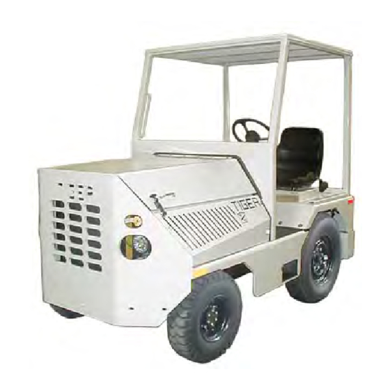
- Page 1 Shown with optional overhead guard Models Inlcuded: TC-030-60 T h e B e s t W a y To G o A b o u t Yo u r B u s i n e s s MANUAL MT-030-60-C Operation, Maintenance, and Replacement Parts Manual Serial Number Range: 183370 - 183373...
- Page 2 Taylor-Dunn has a network of dealers distributed around the globe to support our vehicles. Information regarding vehicle sales, replacement parts, or service should be obtained through your local dealer. A dealer locator can be found on the Taylor-Dunn website at www.taylor-dunn.com.
- Page 3 Section Inde Section Inde Section Inde Section Inde Section Index x x x x Tiger Tractor Model TC-030-60 Operator and Service Manual Section Index Introduction Safety Rules and Operating Instructions General Maintenance Front Axle Service Steering Component Service Engine Service Fuel System Cooling System Transmission Service...
- Page 4 Decades of experience are an invaluable asset, and it is an asset we cherish and protect. Our guiding principle is to provide application- specific solutions, which are reliable, efficient, and economical. Our domestic and international network of quality Taylor-Dunn Dealers and Parts & Service Support keeps our customers moving. Tiger Tractor: Tiger manufacturing has become a leading manufacturer of internal combustion industrial tractors and ground support equipment.
-
Page 5: Table Of Contents
Chapter - 1 Table of Contents About this manual .......... 2 Who Should Read This Manual ..... 2 Responsibilities ..........2 How To Use This Manual ....... 3 Conventions ............3 How to Identify Your Vehicle ......4 Taking Delivery of Your Vehicle ..... 5... -
Page 6: About This Manual
ABOUT THIS MANUAL RESPONSIBILITIES The purchase of this vehicle shows a belief in high Of the Owner... quality products manufactured in the USA. The owner of this or any Taylor-Dunn ® vehicle is Taylor-Dunn ® , a leading manufacturer of electric and... -
Page 7: How To Use This Manual
INTRODUCTION HOW TO USE THIS MANUAL Conventions This manual is organized into five main sections: Symbols and/or words that are used to define warnings, cautions, instructions, or notes found INTRODUCTION throughout this manual. Refer to the examples below. This section describes how to use this service manual and how to identify your vehicle. -
Page 8: How To Identify Your Vehicle
INTRODUCTION HOW TO IDENTIFY YOUR VEHICLE This manual applies to vehicles with the same model and serial numbers listed on the front cover. These vehicles are designed for driving on smooth surfaces in and around facilities such as industrial plants, , airports, nurseries, institutions, motels, mobile home parks, and resorts. -
Page 9: Taking Delivery Of Your Vehicle
The only personnel authorized to repair, modify, or • Check that all wire connections, battery cables, ® adjust any part of this or any Taylor-Dunn vehicle is and other electrical connections are secure. a factory authorized service technician. •... - Page 10 Notes:...
- Page 11 Chapter - TABLE OF CONTENTS Standard Specifications* ....2 Safety Rules and Guidelines ....3 Driver Training Program ..... 3 Driver Qualifications......... 3 Vehicle Controls ......... 4 Instrument Panel ....... 4 1) Ignition Switch ..........4 2) Work Lights ........... 4 3) Oil Pressure ...........
-
Page 12: Standard Specifications
SAFETY RULES AND OPERATING INSTRUCTIONS STANDARD SPECIFICATIONS* ITEM Model SPECIFICATION Occupancy Driver and one passenger Dimensions 103.5 L x 55.5 W x 63 H Inches (2,629 L x 1,410 W x 1,600 H mm) Wheel Base 58.5 inches (1,486 mm) Ground Clearance 6.5 inches (165 mm) Turning Radius... -
Page 13: Safety Rules And Guidelines
SAFETY RULES AND OPERATING INSTRUCTIONS SAFETY RULES AND DRIVER TRAINING PROGRAM GUIDELINES Per ANSI B56.9, the owner of this vehicle shall conduct an Operator Training program for all those who will be It is the responsibility of the owner of this vehicle to assure operating this vehicle. -
Page 14: Vehicle Controls
SAFETY RULES AND OPERATING INSTRUCTIONS VEHICLE CONTROLS INSTRUMENT PANEL 1) Ignition Switch 3) Oil Pressure Note: Rotary switch shown. Also This gauge indicates the available as a keyed switch. engine oil pressure, not the oil level. However, if your engine’s The ignition switch has 3-positions: OFF, RUN, START. -
Page 15: Check Engine Light
SAFETY RULES AND OPERATING INSTRUCTIONS 4) Check Engine Light 6) Battery Volt Meter When the Check Engine Light is on while the engine is This gauge shows you the running, then the ECU has detected conditions that battery voltage when the ignition indicate the engine is not operating correctly. -
Page 16: Heater Blower Switch
SAFETY RULES AND OPERATING INSTRUCTIONS INSTRUMENT PANEL (CONTINUED) 10) Heater Blower Switch 13) 12 Volt Electrical Outlet The blower switch has 4 positions: This outlet can be used to plug in optional electrical accessories. OFF: The blower is OFF when the switch indicator is pointing straight up. -
Page 17: Throttle Pedal
SAFETY RULES AND OPERATING INSTRUCTIONS 1) Throttle Pedal The throttle pedal is located on the floorboard and is intended to be operated by the drivers right foot. It controls the speed of the vehicle and operates similar to the throttle pedal in an automobile. Depress the pedal to increase speed and release the pedal to decrease speed. -
Page 18: Vehicle Operation
SAFETY RULES AND OPERATING INSTRUCTIONS VEHICLE OPERATION Safety Guidelines Starting • Only qualified and trained operators may drive this For additional information, refer to the engine operator’s manual included with your vehicle. vehicle. • Drive only on level surfaces or on surfaces having an incline of no more than 10% (5.6 degrees). -
Page 19: Driving
SAFETY RULES AND OPERATING INSTRUCTIONS Driving Parking Before leaving the vehicle: • Slow down and sound the horn to warn pedestrians or when approaching a corner or other intersection. • After coming to a complete stop, move the shift lever to the Park position. -
Page 20: Refueling
SAFETY RULES AND OPERATING INSTRUCTIONS Refueling Draw Bar Pull (DBP), definition DBP is a measure of pulling force required to move a load. The load may be a trailing load or a pushed load. It The fuel system may be under pressure. If the is normally expressed in pounds or Newtons. -
Page 21: Circuit Breaker (Cb) Panel
SAFETY RULES AND OPERATING INSTRUCTIONS CIRCUIT BREAKER (CB) PANEL Typical location of the CB panel is under the dash on the right side of the fire wall. The location of the CB panel may vary depending on the configuration of the vehicle. Amp# Wire # Function Main Ignition... -
Page 22: Pm Checklist
SAFETY RULES AND OPERATING INSTRUCTIONS NOTE: A full page copy of the Periodic Maintenance Checklist is on the PM CHECKLIST Vehicle Documentation CD under the [Misc] sub folder. Safety Rules and Operating Instructions: MT-030-60-C Page 12... -
Page 23: Maintenance Guidelines For Severe Duty Applications
SAFETY RULES AND OPERATING INSTRUCTIONS Daily Visual inspection: • Tire condition and pressure. • External frame damage (body). • Proper operation of all external lights, internal lights, warning lights, warning alarms and/or horns. • Proper operation of all instrument panel gauges and/or warning lights. •... - Page 24 Notes:...
- Page 25 Chapter - Table of Contents Maintenance Guidelines ........ 2 Lubrication and Fluids Chart ......3 Lubrication Diagram ........4...
- Page 26 Regularly inspect and maintain in a safe working condition, brakes, steering mechanisms, speed and directional control mechanisms, warning devices, lights, governors, guards, and safety devices. • Inspect and maintain battery limit switches, protective devices, electrical conductors, and connections in conformance with Taylor-Dunn’s ® recommended procedures. •...
- Page 27 Maintenance, Service and Repair Lubrication and Fluids Chart Assembly ID# Component QTY Capacity Lubricant Front Axle: King Pin, Upper NLGI Grade 2 lithium multi-purpose grease 10 King Pin, Lower NLGI Grade 2 lithium multi-purpose grease Ball Joint NLGI Grade 2 lithium multi-purpose grease Wheel Bearing NLGI Grade 2 lithium high temp Bearing Grease Hydraulic System (steering/brakes):...
- Page 28 Maintenance, Service and Repair Lubrication Diagram General Maintenance: MT-030-60-C Page 4...
- Page 29 Chapter - TABLE OF CONTENTS Inspect the Front Wheel Bearings and King Pin ......... 2 Adjust Front Wheel Bearings (used bearings) ......2 Adjust Front Wheel Bearings (new bearings) ....... 3 Align Front Wheels ......3 Front Hub, Steering knuckle, King Pin 4 Disassembly ............
-
Page 30: Inspect The Front Wheel Bearings And King Pin
Maintenance, Service, and Repair INSPECT THE FRONT WHEEL ADJUST FRONT WHEEL BEARINGS AND KING PIN BEARINGS (USED BEARINGS) DO NOT use this procedure to set new wheel bearings. Refer to Adjust Front Wheel Bearing for new bearing adjustment procedure. 1. Make sure the ignition switch is in the “OFF” position. -
Page 31: Adjust Front Wheel Bearings (New Bearings)
Maintenance, Service, and Repair ADJUST FRONT WHEEL ALIGN FRONT WHEELS BEARINGS (NEW BEARINGS) Alignment of the front wheels consists of setting the Toe In only. Camber and Caster are fixed and cannot be DO NOT use this procedure to set used wheel bearings. adjusted. -
Page 32: Front Hub, Steering Knuckle, King Pin
Maintenance, Service, and Repair FRONT HUB, STEERING KNUCKLE, KING PIN It is recommended that if a wearable component is replaced on one side of a vehicle, the same components should be replaced on the other side of the vehicle. Reassembly Disassembly Thoroughly clean and inspect all parts. -
Page 33: Replace Front Wheel Bearings
Maintenance, Service, and Repair REPLACE FRONT WHEEL BEARINGS It is recommended that if a wearable component is replaced on one side of a vehicle, the same components should be replaced on the other side of the vehicle. This procedure assumes that the front hub has been removed from the vehicle. -
Page 34: Hardware Torque
Maintenance, Service, and Repair HARDWARE TORQUE If hardware is not listed here, refer to standard torque values in the appendix. Description Foot Pounds Newton Meters Outer Wheel Bearing Nut Ball Joint Clamp 28-32 38-43 Ball Joint Nuts 45-55 61-74 Hub Cap Bolts 27.1 Steering Arm Nuts Tighten to 160 Foot Pounds (217... - Page 35 Chapter - TABLE OF CONTENTS Replace the Steering Cylinder, Hydrostatic Steering ...... 2 Remove .............. 2 Install ..............2 Replace Ball Joint ......2 Wheel Alignment........ 3 Hydraulic System ....... 3 Hardware Torque ....... 3...
- Page 36 Maintenance, Service, and Repair REPLACE THE STEERING REPLACE BALL JOINT CYLINDER, HYDROSTATIC It is recommended that if a wearable component is replaced on one side of a vehicle, the same components should be STEERING replaced on the other side of the vehicle. It is likely that the ball joint will be damaged when removed Remove from the steering arm.
- Page 37 Maintenance, Service, and Repair WHEEL ALIGNMENT HARDWARE TORQUE Refer to Front Axle section If hardware is not listed here, refer to standard torque values in the appendix. Description Foot Pounds Newton Meters Steering wheel nut Ball Joint Clamps 28-32 38-43 Ball Joint Jam Nuts 20-25 27-34...
- Page 38 Notes:...
- Page 39 Manual Part Numbers by engine model: Cummins 4.5L Diesel B4.5 Operation/Maintenance: M7-001-49 Service: M7-001-48 Taylor-Dunn provides an operaror’s manual with every vehicle. These additional Manuals may be purchased through your local Taylor-Dunn® distributor. A service manual order form (D4-010-00) is available on the vehicle CD.
- Page 41 Chapter - TABLE OF CONTENTS Fuel System, Cummins B4.5 Diesel .. 2 Fuel, whether gasoline or LPG, is highly flammable. Use extreme care whenever servicing any component of the fuel system. Allow the engine to cool before starting • work. Confirm all pressurized fuel lines have been •...
- Page 42 Maintenance, Service, and Repair Fuel is highly flammable. Use extreme care whenever servicing any component of the fuel system. Allow the engine to cool before starting work. • Confirm all pressurized fuel lines have been depressurized before opening any fuel line connection. •...
- Page 43 Chapter - TABLE OF CONTENTS Coolant Level ........2 Inspection ............2 Adding Coolant ..........2 Radiator and Hoses ......2 Inspection ............2 Fan Belts ........... 2 Inspect ............... 2 Adjust ..............2 Hardware Torque ....... 3...
- Page 44 Maintenance, Service, and Repair COOLANT LEVEL RADIATOR AND HOSES Inspection The coolant system is pressurized when the Inspect the exterior of the radiator for obstructions and engine is running or hot. damage to the cooling fins. The radiator fins can be Do not remove the radiator cap while the •...
- Page 45 Maintenance, Service, and Repair HARDWARE TORQUE If hardware is not listed here, refer to standard torque values in the appendix. Description Foot Pounds Newton Meters Cooling System: MT-030-60-C Page 3...
- Page 46 Notes:...
- Page 47 Chapter - TABLE OF CONTENTS DIAGNOSIS AND TESTING ......2 GENERAL INFORMATION ......2...
- Page 48 Maintenance, Service, and Repair DIAGNOSIS AND TESTING GENERAL INFORMATION Troubleshooting the automatic transmission is simplified All automatic transmissions are equipped with high by using the proven methods of diagnosis. One of the temperature resistant seals. This includes those seals most important things to remember is that there is a used on the manual and kickdown levers, the 0-rings definite procedure to follow.
- Page 49 Maintenance, Service, and Repair Transmission Service - Ford C6: MT-030-60-C Page 3...
- Page 50 Maintenance, Service, and Repair Transmission Service - Ford C6: MT-030-60-C Page 4...
- Page 51 Maintenance, Service, and Repair Transmission Service - Ford C6: MT-030-60-C Page 5...
- Page 52 Maintenance, Service, and Repair Transmission Service - Ford C6: MT-030-60-C Page 6...
- Page 53 Maintenance, Service, and Repair Transmission Service - Ford C6: MT-030-60-C Page 7...
- Page 54 Maintenance, Service, and Repair Transmission Service - Ford C6: MT-030-60-C Page 8...
- Page 55 Maintenance, Service, and Repair Transmission Service - Ford C6: MT-030-60-C Page 9...
- Page 56 Maintenance, Service, and Repair Transmission Service - Ford C6: MT-030-60-C Page 10...
- Page 57 Maintenance, Service, and Repair Transmission Service - Ford C6: MT-030-60-C Page 11...
- Page 58 Maintenance, Service, and Repair Transmission Service - Ford C6: MT-030-60-C Page 12...
- Page 59 Maintenance, Service, and Repair Transmission Service - Ford C6: MT-030-60-C Page 13...
- Page 60 Maintenance, Service, and Repair Transmission Service - Ford C6: MT-030-60-C Page 14...
- Page 61 Maintenance, Service, and Repair Transmission Service - Ford C6: MT-030-60-C Page 15...
- Page 62 Maintenance, Service, and Repair Transmission Service - Ford C6: MT-030-60-C Page 16...
- Page 63 Maintenance, Service, and Repair Transmission Service - Ford C6: MT-030-60-C Page 17...
- Page 64 Maintenance, Service, and Repair Transmission Service - Ford C6: MT-030-60-C Page 18...
- Page 65 Maintenance, Service, and Repair Transmission Service - Ford C6: MT-030-60-C Page 19...
- Page 66 Maintenance, Service, and Repair Transmission Service - Ford C6: MT-030-60-C Page 20...
- Page 67 Maintenance, Service, and Repair Transmission Service - Ford C6: MT-030-60-C Page 21...
- Page 68 Maintenance, Service, and Repair Transmission Service - Ford C6: MT-030-60-C Page 22...
- Page 69 Chapter - DESCRIPTION TABLE OF CONTENTS The C6 transmission is a three speed unit Capable of ADJUSTMENTS providing automatic upshifts and downshifts through Intermediate Band Adjustment ... 2 the three forward gear ratios. The transmission Is also capable of providing manual selection of first and DESCRIPTIONS second gears.
- Page 70 Maintenance, Service, and Repair Transmission Repair - Ford C6: MT-030-60-C Page 2...
- Page 71 Maintenance, Service, and Repair Transmission Repair - Ford C6: MT-030-60-C Page 3...
- Page 72 Maintenance, Service, and Repair Transmission Repair - Ford C6: MT-030-60-C Page 4...
- Page 73 Maintenance, Service, and Repair Transmission Repair - Ford C6: MT-030-60-C Page 5...
- Page 74 Maintenance, Service, and Repair Transmission Repair - Ford C6: MT-030-60-C Page 6...
- Page 75 Maintenance, Service, and Repair Transmission Repair - Ford C6: MT-030-60-C Page 7...
- Page 76 Maintenance, Service, and Repair Transmission Repair - Ford C6: MT-030-60-C Page 8...
- Page 77 Maintenance, Service, and Repair Transmission Repair - Ford C6: MT-030-60-C Page 9...
- Page 78 Maintenance, Service, and Repair Transmission Repair - Ford C6: MT-030-60-C Page 10...
- Page 79 Maintenance, Service, and Repair Transmission Repair - Ford C6: MT-030-60-C Page 11...
- Page 80 Maintenance, Service, and Repair Transmission Repair - Ford C6: MT-030-60-C Page 12...
- Page 81 Maintenance, Service, and Repair Transmission Repair - Ford C6: MT-030-60-C Page 13...
- Page 82 Maintenance, Service, and Repair Transmission Repair - Ford C6: MT-030-60-C Page 14...
- Page 83 Maintenance, Service, and Repair Transmission Repair - Ford C6: MT-030-60-C Page 15...
- Page 84 Maintenance, Service, and Repair Transmission Repair - Ford C6: MT-030-60-C Page 16...
- Page 85 Maintenance, Service, and Repair Transmission Repair - Ford C6: MT-030-60-C Page 17...
- Page 86 Maintenance, Service, and Repair Transmission Repair - Ford C6: MT-030-60-C Page 18...
- Page 87 Maintenance, Service, and Repair Transmission Repair - Ford C6: MT-030-60-C Page 19...
- Page 88 Maintenance, Service, and Repair Transmission Repair - Ford C6: MT-030-60-C Page 20...
- Page 89 Maintenance, Service, and Repair Transmission Repair - Ford C6: MT-030-60-C Page 21...
- Page 90 Maintenance, Service, and Repair Transmission Repair - Ford C6: MT-030-60-C Page 22...
- Page 91 Maintenance, Service, and Repair Transmission Repair - Ford C6: MT-030-60-C Page 23...
- Page 92 Notes:...
- Page 93 Chapter - TABLE OF CONTENTS Check Oil Level ......... 2 Change Oil ......... 2 Drive Axle Service ......3 Disassembly ........4 Wheelend, Planetary - TA268 Drive Axle ..4 Main Housing Disassembly ......5 Nose Reduction Box Disassembly - TA267 ..6 Prepare Parts for Assembly ....
-
Page 94: Check Oil Level
Maintenance, Service, and Repair CHECK OIL LEVEL CHANGE OIL 1. Make sure the ignition switch is in the “OFF” 1. Make sure the ignition switch is in the “OFF” position. position. 2. Place the transmission shift lever in the Park or 2. -
Page 95: Drive Axle Service
Maintenance, Service, and Repair DRIVE AXLE SERVICE The information on the following pages was provided by the axle manufacturer. This section covers two drive axle configurations: • TA268 - Primary reduction is ring and pinion gears with planetary gear hubs for secondary reduction. Equipped with drum brakes. •... -
Page 96: Disassembly
Maintenance, Service, and Repair DISASSEMBLY Perform the following prior to disassembly. Remove axle from vehicle if required. 2. Clean exterior axle surfaces. Steam clean or pressure washer the complete axle assembly after plugging all breathers and vents. Do not direct full pressure at any seals. (input shall, wheel hubs or brakes) 3. -
Page 97: Main Housing Disassembly
Maintenance, Service, and Repair Main Housing Disassembly thrust washers, four differential pinions, four pinion thrust washers and the differential spider. Both axle ends, brakes, and nose reduction (if equipped) 7. If replacement of the bevel ring gear is required, must be removed before proceeding with this section. remove the twelve capscrews, washers and locknuts 1. -
Page 98: Nose Reduction Box Disassembly - Ta267
Maintenance, Service, and Repair Nose Reduction Box Disassembly - TA267 PREPARE PARTS FOR 1. Loosen input shaft nut, remove washer and input ASSEMBLY flange from then input shaft. 2. Remove input shaft bearing cap screws, lock Cleaning washers and bearing cap. 3. -
Page 99: Assembly
Maintenance, Service, and Repair ASSEMBLY Differential and Bevel Ring Gear Assembly Bevel Pinion and Cage Assembly 1. Press the bevel ring gear firmly against shoulder of 1. Press inner roller bearing firmly against bevel pinion flanged differential case half. Install the twelve shoulder and install inner roller bearing snap ring. -
Page 100: Main Housing And Pinion Cage Assembly
Maintenance, Service, and Repair Main Housing and Pinion Cage Assembly Nose Reduction Box Assembly - TA267 1. If assembling a TA267; skip to step #5. 1. Press input shaft oil seal to bottom of bore in reduction box case. 2. If assembling a TA268; apply a light film of sealing compound to both sides of the pinion cage gasket. -
Page 101: Planetary Wheelend
Maintenance, Service, and Repair 13. Thread the wheel bearing adjustment nut onto the Planetary Wheelend spindle. Tighten nut to 400 foot pounds. Rotate the 1. Before starting brake reassembly, apply a small wheel hub while rapping the hub several times with quantity of EP-2 grease to the following brake a 10 pound dead blow mallet, Retighten the nut to components:... - Page 102 Maintenance, Service, and Repair Planetary Wheel End Drive Axle: MT-030-60-C Page 10...
-
Page 103: Standard Wheelend
Maintenance, Service, and Repair 12. Assemble the piston boot to the piston. Install the Standard Wheelend piston in the caliper housing bore, pushing it to the 1. If inner bearing cup was removed from carrier and bottom of the bore. Seat the piston boot in caliper tube assembly, press new bearing cup to bottom of housing boot bore. - Page 104 Notes:...
- Page 105 Perform all maintenance and repairs in a clean environment. Do not use cloth or paper towels to clean components due to possible contamination with lint or other fiber. Failure to follow these guidelines will result in premature failure of hydraulic system components. Current Taylor-Dunn brakes are asbestos free. ®...
-
Page 106: Front Brake
12. Thoroughly clean the sliding surfaces of the bracket and housing. 13. Apply an anti-seize lubricant to the machined “V” groove Current Taylor-Dunn brakes are asbestos free. in the brake bracket. Be careful not to apply too much ®... -
Page 107: Rebuild Caliper
Maintenance, Service, and Repair 16. Measure the thickness of the rotor. If the thickness of the rotor is less than the service limit then the rotor must be replaced. Refer to the front axle section for information on removing/installing the brake rotor. 17. -
Page 108: Rear Brake - Axle Ta267
Maintenance, Service, and Repair REAR BRAKE - AXLE TA267 Service Limits: Brake pad Thickness: 1/16” (1.6 mm) Rotor Thickness: 0.826” (21 mm) Rotor runout: 0.005 inches (0.127 mm). It is recommended that if a wearable component is replaced on one side of a vehicle, the same components should be replaced on the other side of the vehicle. -
Page 109: Adjust Parking Brake
Release the park brake and test drive the vehicle. drum must be replaced. Secondary Adjustment 1. Make sure the ignition switch is in the “OFF” Current Taylor-Dunn brakes are asbestos free. ® position, then remove the key. However, there is the possibility that the original brakes were replaced with aftermarket parts 2. -
Page 110: Hydraulic System
Maintenance, Service, and Repair HYDRAULIC SYSTEM HARDWARE TORQUE The brake hydraulic system is shared by the steering hydraulic If hardware is not listed here, refer to standard torque values system. Information for both systems are combined into the in the appendix. Hydraulic System section. - Page 111 Chapter - TABLE OF CONTENTS Front Suspension ......2 Rear Suspension ....... 2 Hardware Torque ....... 3...
- Page 112 Maintenance, Service, and Repair FRONT SUSPENSION REAR SUSPENSION Suspension: MT-030-60-C Page 2...
- Page 113 Maintenance, Service, and Repair HARDWARE TORQUE If hardware is not listed here, refer to standard torque values in the appendix. Description Foot Pounds Newton Meters Rear Spring U-bolts Rear Spring, Front Eye Front Spring, Front Eye ** - Tighten untill the spring hangers or mounting brackets are solid against the spring eye and then loosen the nut 1/4 turn.
- Page 114 Notes:...
- Page 115 Chapter - TABLE OF CONTENTS Tire Inflation ........2 Tire Inspection ........2 Tire/Wheel Assembly ......3 Remove/Install ........... 3 Hardware Torque ....... 3...
- Page 116 Maintenance, Service, and Repair TIRE INFLATION The tire/wheel assemblies for this vehicle are foam filled. Tire inflation is not required. TIRE INSPECTION 9. Inspect the inner and outer side walls for cracks. If any cracks are seen, then the tire should be replaced. 1.
- Page 117 Maintenance, Service, and Repair TIRE/WHEEL ASSEMBLY HARDWARE TORQUE If hardware is not listed here, refer to standard torque values in the appendix. Remove/Install Description Foot Pounds Newton Meters Wheel Nut, Front 90-110 122-149 1. Make sure the start switch is in the “OFF” Wheel Nut, Rear 110-120 149-162...
- Page 118 Notes:...
- Page 119 Chapter - TABLE OF CONTENTS Cleaning ..........2 Testing ..........3 Watering ..........4 Storing ..........5 Storage ............... 5 Returning to Service .......... 5 Remove/install ........6 Hardware Torque ....... 7 • • • • • Explosive mixtures of Hydrogen gas are present within battery cells at all times.
-
Page 120: Cleaning
Maintenance, Service, and Repair CLEANING • • • • • Explosive mixtures of Hydrogen gas are 1. Make sure the start switch is in the “OFF” present within battery cells at all times. Do not position, then remove the key. work with or charge battery in an area where open flames (including gas furnace or water 2. -
Page 121: Testing
Maintenance, Service, and Repair TESTING Specific Gravity NOTE: The battery must be fully charged before • • • • • Explosive mixtures of Hydrogen gas are performing this test. present within battery cells at all times. Do not This test should only be performed on non-maintenance work with or charge battery in an area where free batteries. -
Page 122: Watering
Maintenance, Service, and Repair WATERING • • • • • Explosive mixtures of Hydrogen gas are Do not overfill the batteries. Over filling the present within battery cells at all times. Do not batteries may cause the batteries to boil over work with or charge battery in an area where and result in severe bodily injury or property open flames (including gas furnace or water... -
Page 123: Storing
Maintenance, Service, and Repair STORING Storage Thoroughly clean the battery and battery compartment. Cleaning Refer to in this section for information regarding cleaning the battery. Check the electrolyte level and charge the battery. Refer Watering in this section for information regarding checking the electrolyte level. -
Page 124: Remove/Install
Maintenance, Service, and Repair REMOVE/INSTALL • • • • • Explosive mixtures of Hydrogen gas are present within battery cells at all times. Do not work with or charge battery in an area where open flames (including gas furnace or water heater pilots), sparks, cigarettes, or any other sources of combustion are present. -
Page 125: Hardware Torque
Maintenance, Service, and Repair HARDWARE TORQUE If hardware is not listed here, refer to standard torque values in the appendix. Note: Depending on options ordered with the vehicle, the battery may have either a post or stud terminal. Description Inch Pounds Newton Meters Battery Terminal (clamp type) 48-60... - Page 126 Notes:...
- Page 127 Chapter - 16 CONTENTS Wire Diagram, Chassie (P1) ....2 Wire Diagram, Chassie (P2) ....3 Wire Diagram, Engine Shutdown ..4...
- Page 128 Wire Diagrams Note: A fill size diagram is avaiable on the CD provided with WIRE DIAGRAM, CHASSIE (P1) the vehicle. The diagram # is SCH-00036. Wire Diagrams: MT-030-60-C Page 2...
- Page 129 Wire Diagrams Note: A fill size diagram is avaiable on the CD provided with WIRE DIAGRAM, CHASSIE (P2) the vehicle. The diagram # is SCH-00036. Wire Diagrams: MT-030-60-C Page 3...
- Page 130 Wire Diagrams WIRE DIAGRAM, ENGINE SHUTDOWN Wire Diagrams: MT-030-60-C Page 4...
- Page 131 Chapter - TABLE OF CONTENTS Hydraulic Diagram ......2 Discharge the Accumulator ....3 Brake Pedal Assembly ....... 3 Modulating Valve (brake) ....3 Accumulator Charging Valve ....3 Bleed Hydraulic Brake System ..3 Adjust Parking Brake (drive shaft brake drum) ....4 Primary Adjustment ..........
-
Page 132: Hydraulic Diagram
Maintenance, Service, and Repair HYDRAULIC DIAGRAM Before servicing any component in the hydraulic system, the accumulator circuit must be discharged. Failure to fully discharge the accumulator could result in severe personal injury or death. Hydraulics: MT-030-60-C Page 2... -
Page 133: Discharge The Accumulator
Maintenance, Service, and Repair DISCHARGE THE ACCUMULATOR CHARGING ACCUMULATOR VALVE Before servicing any component in the hydraulic Before servicing any component in the hydraulic system, the accumulator circuit must be discharged. system, the accumulator circuit must be discharged. Failure to fully discharge the accumulator could Failure to fully discharge the accumulator could result in severe personal injury or death. -
Page 134: Adjust Parking Brake (Drive Shaft Brake Drum)
Release the park brake and test drive the vehicle. drum must be replaced. Secondary Adjustment 1. Make sure the ignition switch is in the “OFF” Current Taylor-Dunn brakes are asbestos free. ® position, then remove the key. However, there is the possibility that the original brakes were replaced with aftermarket parts 2. -
Page 135: Hydraulic Pump
Maintenance, Service, and Repair HARDWARE TORQUE HYDRAULIC PUMP If hardware is not listed here, refer to standard torque values To obtain the most current service and repair information, go in the appendix. to the following web site and download manual BLN-10168: Description Foot Pounds Newton Meters... - Page 136 Notes:...
- Page 137 Chapter - Illustrated Parts TABLE OF CONTENTS Axle Assembly, Front ........2 Heater ............22 Axle Assembly, Rear Secondary Gears ..4 Hitch ............. 22 Axle Assembly, Rear Axles ......6 Hydraulic Fittings, P1 ........24 Axle Assembly, Rear Primary Gears ..... 8 Hydraulic Fittings, P2 ........
-
Page 138: Axle Assembly, Front
Replacement Parts Axle Assembly, Front Refer to Steering pages for items that are grayed Parts: MT-030-60-C * Not available at time of printing Page 2... - Page 139 Replacement Parts Axle Assembly, Front Item No. Part No. Description 88-401-46 Bolt 88-401-96 Washer 500845 Hub Cap 500844 Gasket 500841 Washer 500843 Washer 500842 500849 Bearing 500850 Race 500898 Wheel Stud 500846 500851 Seal 501042 Knuckle, Right 501041 Knuckle, Left 500857 Kit, King Pin (left and right) 14-900-14...
-
Page 140: Axle Assembly, Rear Secondary Gears
Replacement Parts Axle Assembly, Rear Secondary Gears Axle Assembly, Rear Secondary Gears Item No. Part No. Description 506700 Complete Axle Assembly A10641 Gasket A11451 Bearing cage assembly A11432 Roll pin A10182 Inner cone bearing A11472 Shim pac A11484 Pinion gear assembly A11485 Ring and Pinion gear A11487... - Page 141 Replacement Parts Axle Assembly, Rear Secondary Gears (cont’d) Item No. Part No. Description TIG-2001-121 Axle gear TIG-2001-127 Thrust Washer, diff gear A10164 Differential gear TIG-2001-123 Differential spider A10167 Bearing TIG-2001-291 Hardware kit A11427 Cap screw A10174 Washer A10384 TIG-2001-157 Gasket A11468 Cap screw A10174...
-
Page 142: Axle Assembly, Rear Axles
Replacement Parts Axle Assembly, Rear Axles Parts: MT-030-60-C * Not available at time of printing Page 6... - Page 143 Replacement Parts Axle Assembly, Rear Axles Item No. Part No. Description A11418 Bearing race TIG-2001-169 Bearing A11418 Bearing race TIG-2001-175 Gasket A11425 Spacer A11434 Shim, 0.003 A11436 Shim, 0.005 (package of 10) A11437 Shim, 0.010 (package of 5) A11454 Seal 401602 Washer A11469...
-
Page 144: Axle Assembly, Rear Primary Gears
Replacement Parts Axle Assembly, Rear Primary Gears Axle Assembly, Rear Primary Gears Item No. Part No. Description A11480 Brake disc A10165 Washer A11467 Cap screw A11481 A10182 Bearing TIG-2001-231 Washer A11421 34475 Washer A11450 Stud A10642 Gear case assembly TIG-2001-263 Dowel Parts: MT-030-60-C * Not available at time of printing... -
Page 145: Brakes, Brake Pedal Linkage
Replacement Parts Axle Assembly, Rear Primary Gears (cont’d) Item No. Part No. Description A11423 Bearing A11430 Snap ring A11445 Bearing cap A11471 Cap screw TIG-2001-217 Washer 401577 A11428 TIG-2001-323 Gear A10189 A10190 Locking washer A11467 Cap screw A11465 A11422 Bearing A11466 Plug Brakes, Brake Pedal Linkage... -
Page 146: Brakes, Brake Lines
Replacement Parts Brakes, Brake Lines Parts: MT-030-60-C * Not available at time of printing Page 10... - Page 147 Replacement Parts Brake Lines Item No. Part No. Description 99-702-03 Brake Line, Brake Valve Top Port to T-fitting (rear brakes) 503206 Brake Line, T to Left Front Brake Hose 500148A Brake Line, T to Rear Axle (rear calipers) 503207 Brake Line, Front Left Hose to Front Right Hose 99-702-04 Brake Line, Brk Valve Bottom Port to T-fitting (Frnt/Rr Brakes) 1 500147...
-
Page 148: Brakes, Front Axle
Replacement Parts Brakes, Front Axle Front Brakes Item No. Part No. Description 504480 Caliper Assembly, Left 504480 Caliper Assembly, Right 500375 Mounting Bracket 500374 Rotor 88-402-07 Bolt, 7/16 Grade 8 88-402-28 Nut, Reversable Lock 88-401-77 Bolt, Caliper Mounting 88-401-96 Washer, Split Lock, Caliper Mounting 903641 Piston 41-348-62... -
Page 149: Brakes, Parking Brake
Replacement Parts Brakes, Parking Brake Illustration Not Available Item No. Part No. Description 500543 Lever, Park Brake 500022-V6 Mounting Bracket 500039 Linkage, Hand Lever to bellcrank 77923 Drum, Park Brake CL-999378-2 Shoe, Park Brake (set of two shoes) 505661 Brake Assembly, includes the following Bellcrank Stud, Bellcrank, Washer, Nut, linkages 500587 Bracket, Park Brake Mounting... -
Page 150: Brakes, Rear Axle
Replacement Parts Brakes, Rear Axle Illustration Not Available Item No. Part No. Description 504528 Caliper Assembly 41-490-43 Kit, Brake Pad Replacement Includes pads for all 4 calipers 507017 Seal kit, Caliper, Mineral Oil Illustration Not Available Item No. Part No. Description 500307-D CAB WLDMNT 78"... -
Page 151: Cab Doors
Replacement Parts Cab Doors Illustration Not Available Item No. Part No. Description 502641 Door Assembly, complete Left 502642 Door Assembly, complete Right 500303A-6 WEATHER STRIP, DOORS 12.5 500304-11 COVER, DOOR, LATCH, RH 500303-11 COVER, DOOR, LATCH, LH 500306 HINGE, DOOR, CAB, SHORT 500311 WINDOW RT DOOR >... -
Page 152: Electrical, Miscellaneous
Replacement Parts Electrical, Miscellaneous Illustration Not Available Item No. Part No. Description 502556 Battery Cable, Positive 501389 Battery Cable, Negative 505326 Cable, Alternator 500364 Boot, Positive Starter Terminal or Battery 504933 BATTERY/GROUP 24M 500098 Battery Hold Down Bar 502556A Boot, Positive 50-243-16 Rod, Hold Down 500263... -
Page 153: Engine, Cummins
Replacement Parts Engine, Cummins Illustration Not Available Item No. Part No. Description 503830 ENGINE, CUMMINS B4.5-C 80HP 505499 Bracket, Frame Mounting 507014 Bracket, Engine Mounting, Right 507015 Bracket, Engine Mounting, Left 505801 Mount, Engine 67-500-21 Oil Filter 501331 ENGINE MONITORING SYSTEM Parts: MT-030-60-C * Not available at time of printing Page 17... -
Page 154: Engine, Cooling System
Replacement Parts Engine, Cooling System Item No. Part No. Description 504674 Fitting, Engine Coolant Inlet 504510 Hose, Lower 506344 Clamp 500111-A Mount, Radiator 88-401-31 88-401-40 Washer, Flat 88-401-41 Washer, Split Lock 507016 Shroud, Fan 500103-FX Radiator 500262 Cap, Radiator (13 psi) 500130 Kit, Overflow Reservoir 01-900-60... -
Page 155: Engine, Intake/Air Cleaner
Replacement Parts Engine, Intake/Air Cleaner Item No. Part No. Description K1T-700-81 Bracket, Mounting 500805-7-B Bracket, Clamp 500805-7-A Assembly, Air Filter 67-500-01 Element, Air Filter 98-550-15 Hose, Coupling 504623 Fitting, Ait Intake K1T-700-97 Clamp K1T-701-23 Duct, Intake K1T-700-97 Clamp 504274 Hose, Coupling 503444 Gauge, Air Filter 500644... -
Page 156: Exhaust, Cummins Diesel
Replacement Parts Exhaust, Cummins Diesel Illustration Not Available Item No. Part No. Description K1T-600-04 HEADPIPE K1T-600-05 WELDMENT TAILPIPE/MUFFLER K1T-700-96 HOSE CLAMP, MUFFLER MOUNT K1T-701-00 BRACKET, EXHAUST MOUNT K1T-600-10 EXHAUST HANGER WLDMT 500973 CLAMP, MUFFLER INLET PIPE 502522 CLAMP, HOSE 503954 MUFFLER WRAP 2"... -
Page 157: Fuel System, Cummins Diesel
Replacement Parts Fuel System, Cummins Diesel Item No. Part No. Description 99-803-02 Fuel Line, Return 504438 Pocket, Fuel Filler 500023-A Fuel Tank (includes #6 and #9) 500024-A BRACKET/FUEL TANK/18 GAL 500201 Adaptor 504087 Adaptor Part of Fuel Tank Pickup Tube 500201 Adaptor 99-803-01... -
Page 158: Heater
Replacement Parts Heater Illustration Not Available Item No. Part No. Description 32371 HOSE 5/8 GENL PRP 350 PSI RED Per Foot 4-2777647 Cable, Heater Valve 500617 CAB HEATER VENT 500661 CLAMP, HOSE, #10 502028 Y CONNECTOR 5/8 HOSE 502549 HEATER/DEFROSTER KIT 94211 VALVE Hitch... - Page 159 Replacement Parts Parts: MT-030-60-C * Not available at time of printing Page 23...
-
Page 160: Hydraulic Fittings, P1
Replacement Parts Hydraulic Fittings, P1 Before servicing any component in the hydraulic system, the accumulator circuit must be discharged. Failure to fully discharge the accumulator could result in severe personal injury or death. Parts: MT-030-60-C * Not available at time of printing Page 24... - Page 161 Replacement Parts Hydraulic Fittings P1 Item No. Part No. Description Connector, Hydraulic (tractor) Connector, Hydraulic (trailer) See P3 Tank, Small 504478 Tank, Large 504483 Filter 201376 Valve, Ball 504491 Pump, Hydraulic (Includes #8**) 504920 Fitting, T 504664** Valve, Relief** 504506 Valve, Accumulator Charge 504525 Accumullator, 0.75 gl...
-
Page 162: Hydraulic Fittings, P2
Replacement Parts Hydraulic Fittings, P2 Parts: MT-030-60-C * Not available at time of printing Page 26... - Page 163 Replacement Parts Hydraulic Fittings P2 Item No. Part No. Description K1T-400-64 Fitting, 201208 ADAPTOR,1/2" JIC X #12 SAE/ORB 504110 RUN TEE STR THD O-RING 201208 ADAPTOR,1/2" JIC X #12 SAE/ORB K1T-700-63 #8 ORING TO #6 JIC, 90 DEG K1T-700-79 Plug, Pressurre Gauge Outlet 504110 RUN TEE STR THD O-RING 201318...
-
Page 164: Hydraulic Fittings, P3
Replacement Parts Hydraulic Fittings, P3 Before servicing any component in the hydraulic system, the accumulator circuit must be discharged. Failure to fully discharge the accumulator could result in severe personal injury or death. Parts: MT-030-60-C * Not available at time of printing Page 28... - Page 165 Replacement Parts Hydraulic Fittings, P3 Item No. Part No. Description K1T-700-59 Fitting, 1/2” Tee K1T-700-58 Fiting, 1/2” Nipple (to tank) 504539 Tank, Small 504575 Cap/Filter Screen Assembly K1T-700-59 Fitting, 1/2” Tee K1T-700-58 Fiting, 1/2” Nipple (to tank) 201176 Adaptor, 1/2 Pipe - JIC (on bottom) 201176 Adaptor, 1/2 Pipe - JIC K1T-700-75...
-
Page 166: Instrument Panel
Replacement Parts Instrument Panel Item No. Part No. Description 500128 Switch, Ignition (keyless) 0 or 1 500550 Switch, Work Lights 500116 Gauge, Oil Pressure 501332 MIL Light, Lens Only 502321 Bulb 500545 Gauge, Coolant Temperature 502452 Gauge, Volts 500546 Gauge, Fuel 500537 Gauge, Hour Meter 71-039-35... -
Page 167: Lights
Replacement Parts Lights Item No. Part No. Description 72-005-30 Headlight 500181 Taillight 500180 Backup Light 504420 Reflector, Front Round 502142 Reflector, Side, Red 502143 Reflector, Side, Amber See Instrument Panel 502321 Bulb, Shift Light 502321 Bulb, Fuel Gauge 72-005-00 Work Lights, Rear Shown 504025 Harness, Work LIghts... -
Page 168: Linkage, Throttle
Replacement Parts Linkage, Throttle Item No. Part No. Description 500864 Spring 503931 Mounting bracket (not shown) 88-400-03 Bolt 88-400-90 Washer 88-400-75 504536 Clevis, Hand Throttle 61410-57 Cable, Hand Throttle 61675 Clamp 4-277578 Cable, Throttle 61675 Clamp 96-852-00 Rod End K1T-600-02 Bracket, Throttle Cable K1T-600-03 PLATE,ACCEL BRACKET COVER (not shown) -
Page 169: Radio System
Replacement Parts Radio System Illustration Not Available Item No. Part No. Description 72-017-16 Stereo 72-017-17 Speaker set (2) 72-017-18 Antenna K1T-700-22 Speaker Box K1T-700-24 Speaker grill K1T-700-25 Cover Ring, Speaker K1T-700-23 Mounting Bracket, Speaker Box K1T-700-72 Housing, Stereo Parts: MT-030-60-C * Not available at time of printing Page 33... -
Page 170: Steering, Mechanical Linkage
Replacement Parts Steering, Mechanical Linkage Steering Linkage Item No. Part No. Description 14-900-10 Steering Arm, Right 504381 Steering Arm, Left 500563 Cotter Pin 500838 500837 Nut, Castle Nut, Castle, included w ball joint 88-527-16 Cotter Pin 86-510-00 Clamp, Ball Joint 18-000-11 Ball Joint, Left Thread 18-000-10... -
Page 171: Suspension, Front
Replacement Parts Suspension, Front Item No. Part No. Description 500582 Spring, Leaf K1T-700-13 Bushing, Spring Eye, Bronze 500046 U-bolt 88-402-75 Nut, U-bolt 88-402-85 Washer 500045 Plate, U-bolt 88-402-94 Bolt, Spring Eye (rear) K1T-700-11 Bolt, Spring Eye (front w/grease fitting) 88-403-10 Washer 88-403-05 88-402-52... -
Page 172: Suspension, Rear
Replacement Parts Suspension, Rear Item No. Part No. Description 500061 Spring, Leaf K1T-700-14 Bushing, Spring Eye, Bronze 500055 U-bolt,Driver side Inner (long) 500059 U-bolt, (short) 88-403-28 88-403-10 Washer 506319 Plate, U-bolt K1T-700-12 Bolt, Spring Eye, Front (w/grease fitting) 88-402-94 Bolt, Spring Eye, Rear 88-403-10 Washer 88-403-05... -
Page 173: Transmission Assembly / Drive Shaft
Replacement Parts Transmission Assembly / Drive Shaft Item No. Part No. Description See bulletin BUL-10-02-001 Transmission Assembly 500011-V6 MOUNT BRKT TRANS F4.9 502324 DIPSTICK TUBE FORD C6 502323 Dipstick 505630 ORING, C6 DIPSTICK TUBE 503709 Hose Assembly, Radiator to Transmission 503708 Hose Assembly, Transmission to Radiator 503829... -
Page 174: Transmission Components (P1)
Replacement Parts Transmission Components (p1) Parts: MT-030-60-C * Not available at time of printing Page 38... -
Page 175: Transmission Components (P2)
Replacement Parts Transmission Components (p2) Parts: MT-030-60-C * Not available at time of printing Page 39... -
Page 176: Transmission Components (P3)
Replacement Parts Transmission Components (p3) Parts: MT-030-60-C * Not available at time of printing Page 40... -
Page 177: Transmission Components (P4)
Replacement Parts Transmission Components (p4) Parts: MT-030-60-C * Not available at time of printing Page 41... -
Page 178: Wheels And Tires
Replacement Parts Wheels and Tires Item No. Part No. Description 503259 Wheel Assembly Fron, Foam Filled 503343 Wheel Assembly, Front, 650 x 10 500164 Tire, 6.50 x 10, includes tube 500972 Wheel, 10 x 5.5 503260 Wheel Assembly, Rear, Foam Filled 502758 Wheel Assembly, Rear 500257... - Page 179 Contents Appendix A: Suggested Torque Limits for Standard Hardware ......2 Hardware Identification ...... 2 Standard Head Markings ........2 Hex Bolts ............2 Other Bolts ............2 Hex Nuts ............3 Hex Lock Nuts (stover) ........3 Other Nuts ............3 Generic Torque Values ........
-
Page 180: Appendix A: Suggested Torque Limits For Standard Hardware
Appendixes APPENDIX A: SUGGESTED TORQUE LIMITS FOR STANDARD HARDWARE HARDWARE IDENTIFICATION Standard Head Markings NOTE: Torque value used should be for lowest grade of hardware used. If a grade 2 nut is used on a grade 8 bolt, use grade 2 torque value. NOTE: Toque values specified are for clean dry threads. -
Page 181: Hex Nuts
NOTE: Nuts with no markings are to be treated as S.A.E. Grade A S.A.E. Grade B S.A.E. Grade C Grade L’9 Other Nuts Other nuts used by Taylor-Dunn ® should be treated as S.A.E. grade A Appendixes *Not available at time of printing... -
Page 182: Generic Torque Values
Appendixes Generic Torque Values All torque values are for clean dry zinc plated threads in noncritical steel assemblies of the same hardess specification. Reduce torque approximately 10-15% for lubricated threads. Refer to the service section assembly procedure for critical torque values. Imperial (inch), Foot Pounds Imperial (inch), Newton Meters Grade, SAE... - Page 183 Appendixes All torque values are for clean dry zinc plated threads in noncritical steel assemblies of the same hardess specification. Reduce torque approximately 10-15% for lubricated threads. Refer to the service section assembly procedure for critical torque values. Metric, Newton Meters Metric, Foot Pounds Grade, N-m Grade, N-m...
-
Page 184: Appendix B: Brake Lining Handling Precautions
Appendixes APPENDIX B: BRAKE LINING HANDLING PRECAUTIONS Taylor-Dunn does not currently supply asbestos fiber-brake pads/ shoes with any vehicle. However, there is the possibility that the original brake pads/shoes were replaced with aftermarket pads/shoes containing asbestos. Since this possibility does exist, the brake pads/ shoes should be handled as if they do contain asbestos. - Page 185 Model B 1-00...
- Page 186 Taylor-Dunn Mfg. ® 2114 W. Ball Rd. Anaheim, CA 92804 (800)-688-8680 (714) 956-4040 (FAX) (714) 956-0504 Visit our Website: www.taylor-dunn.com...
Need help?
Do you have a question about the Tiger TC-030-60 and is the answer not in the manual?
Questions and answers