Chapters
Table of Contents
Troubleshooting

Related Manuals for Taylor-Dunn TT-316-36


Summary of Contents for Taylor-Dunn TT-316-36
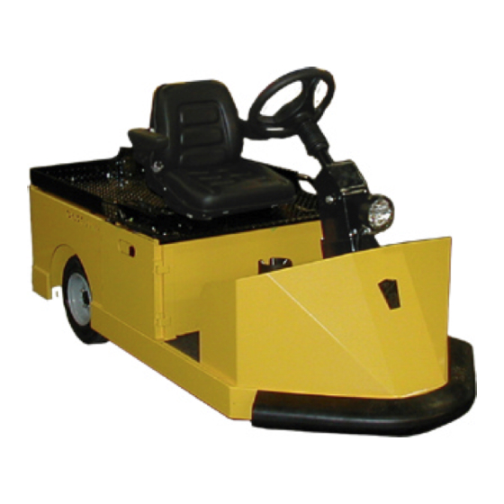
- Page 1 Models Inlcuded: TT-316-36 (TT3-16) T h e B e s t W a y T o G o A b o u t Y o u r B u s i n e s s MANUAL MT-316-00 Operation, Troubleshooting and...
- Page 3 Address inquiries to Reference Permissions, Taylor-Dunn Mfg., 2114 W. Ball Road, Anaheim, CA 92804 ® TAYLOR-DUNN SERVICE CENTER For more information about this and other Taylor-Dunn manuals, please write Taylor-Dunn ® ® Taylor-Dunn Mfg.
- Page 4 B2-10 Ambulance B2-48 With Dump Bed Option B2-48 with Steel Cab, Foldaway 4-Passenger Seat and Stake Sides ET 3000 P2-50 30,000 Pound Tow Tractor ET1-50 Full Size Truck...
-
Page 5: Table Of Contents
Section Index Taylor-Dunn Electic Tow Tractor Model TT-316-36 Operator and Service Manual Section Index Introduction Safety Rules and Operating Instructions General Maintenance Front Axle Service Steering Component Service Brakes Service Motor Service Transmission Service Suspension Tires and Wheels Battery Service... - Page 7 Table of Contents About this manual ......... 2 Who Should Read This Manual ....2 Responsibilities ..........2 How To Use This Manual ......3 Conventions .............. 3 How to Identify Your Vehicle ......4 Taking Delivery of Your Vehicle ....5...
-
Page 8: Introduction
The purchase of this vehicle shows a belief in high Of the Owner... quality products manufactured in the USA. ® ® The owner of this or any Taylor-Dunn vehicle is Taylor-Dunn , a leading manufacturer of electric responsible for the overall maintenance and repairs burden and personnel carriers since 1949, wants to of the vehicle, as well as the training of operators. -
Page 9: Safety Rules And Operating Instructions
INTRODUCTION HOW TO USE THIS MANUAL Conventions This manual is organized into five main sections: Symbols and/or words that are used to define warnings, cautions, instructions, or notes found INTRODUCTION throughout this manual. Refer to the examples below. This section describes how to use this service manual and how to identify your vehicle. -
Page 10: How To Identify Your Vehicle
INTRODUCTION HOW TO IDENTIFY YOUR VEHICLE This manual applies to vehicles with the same model and serial numbers listed on the front cover. These vehicles are designed for driving on smooth surfaces in and around facilities such as industrial plants, nurseries, institutions, motels, mobile home parks, and resorts. -
Page 11: Taking Delivery Of Your Vehicle
The only personnel authorized to repair, modify, or • Check that all wire connections, battery adjust any part of this or any Taylor-Dunn ® vehicle is cables, and other electrical connections are a factory authorized service technician. - Page 13 TABLE OF CONTENTS Standard Specifications Tow Tractor .. 2 Safety Rules and Guidelines ..... 3 Driver Training Program ....3 Driver Qualifications..........3 Vehicle Controls ........ 4 Key-Switch ............4 Forward-Off-Reverse Switch ........ 4 Hi-Low Switch (optional) ........4 Headlight Switch ..........
-
Page 14: Safety Rules And Operating Instructions
SAFETY RULES AND OPERATING INSTRUCTIONS STANDARD SPECIFICATIONS TOW TRACTOR ITEM SPECIFICATION Occupancy Driver only, no passengers Dimensions 208.3 L x 101 W x 111.1 H Centimeters 82 L x 39.75 W x 43.75 H Inches Turning Radius 178.6 Millimeters (70.3 inches) Dry Weight (Without Battery) 499 kg (1,100 lbs) Battery Compartment Dimensions... -
Page 15: Safety Rules And Guidelines
SAFETY RULES AND OPERATING INSTRUCTIONS SAFETY RULES AND DRIVER TRAINING PROGRAM GUIDELINES According to ANSI B56.8, the owner of this vehicle shall conduct an Operator Training program for all those who It is the responsibility of the owner of this vehicle to assure will be operating this vehicle. -
Page 16: Vehicle Controls
SAFETY RULES AND OPERATING INSTRUCTIONS VEHICLE CONTROLS Key-Switch A key-switch, located in the middle of the control console, turns on the vehicle. Rotate the key clockwise to turn Do not turn off the key switch while the the vehicle power on, counterclockwise to turn the vehicle vehicle is in motion unless the vehicle must power off. -
Page 17: Horn Switch (1)
SAFETY RULES AND OPERATING INSTRUCTIONS Horn Switch (1) The horn switch is located on the left side of the floorboard. Depress the switch with your left foot to sound the horn, release it to turn it off. Foot Brake Pedal (2) The foot brake pedal, is located to the left of the accelerator pedal, it is for operation with the right foot only. -
Page 18: Steering
SAFETY RULES AND OPERATING INSTRUCTIONS Steering The steering wheel and steering system are similar to an automobile. To turn right, turn the steering wheel clockwise. To turn left, turn the steering wheel counter- clockwise. Tilt/Telescoping Steering Tilt: To tilt the steering up or down, pull on the tilt locking handle and position the steering wheel as required. -
Page 19: Smart View Display
SAFETY RULES AND OPERATING INSTRUCTIONS Smart View Display The Smart View Display (SVD) functions as a Battery Status Indicator (BSI), Hour Meter (HM), speed controller status monitor, and as an optional maintenance monitor feature. The operation of each of these functions is listed below. BSI: A bar graph representing the current state of charge Speed controller status: The display will indicate a fault is located across the top of the display. -
Page 20: Smart View Display Fault Codes
SAFETY RULES AND OPERATING INSTRUCTIONS Smart View Display Fault Codes Example of Fault Code 4003 displayed on the SVD Fault Code Description Corrective action 01004 Discharged battery or defective wiring. Charge the battery. If the battery is good, check wiring to the controller. (note 2) 01005 Speed control overheated. -
Page 21: Vehicle Operational Guidelines
SAFETY RULES AND OPERATING INSTRUCTIONS While driving: VEHICLE OPERATIONAL • Slow down and sound the horn to warn pedestrians GUIDELINES or when approaching a corner or other intersection. • No reckless driving. Safety Guidelines • Do not drive this vehicle on steep inclines or where •... -
Page 22: Parking
SAFETY RULES AND OPERATING INSTRUCTIONS Parking Before leaving the vehicle: This vehicle is equipped with regenerative • braking. Follow these steps before towing this Set the parking brake. vehicle. • Set the forward-off-reverse switch to the ` “OFF” 1. To tow this vehicle the start switch must be position. -
Page 23: Charging Your Vehicle
SAFETY RULES AND OPERATING INSTRUCTIONS CHARGING YOUR VEHICLE Explosive mixtures of Hydrogen gas are Battery electrolyte is poisonous and present within battery cells at all times. Do dangerous. It contains sulfuric acid. Avoid not work with or charge battery in an area contact with skin eyes or clothing. -
Page 24: Industrial Charger Operation
SAFETY RULES AND OPERATING INSTRUCTIONS ® Lestronic II Charger Operation Charging Time ® The Lestronic II charger is a semi-automatic charging Average charging time is 8 to 10-hours. The time required system. The charger will turn itself ON when the AC to fully charge your batteries will vary depending on: power cord is connected to the AC power source and •... -
Page 25: Periodic Maintenance Checklist
SAFETY RULES AND OPERATING INSTRUCTIONS PERIODIC MAINTENANCE CHECKLIST Semi - Weekly Monthly Quaterly Annualy Maintenance Item Annual (20hrs) (80hrs) (250hrs) (1000hrs) (500hrs) Check Condition of Tires and Tire Pressure Check All Lights, Horns, Beepers and Warning Devises Check and Fill Batteries Check Brake System Check Steering System Check for Fluid Leaks... -
Page 26: Standard Periodic Maintenance Schedule For The Smart View Display
SAFETY RULES AND OPERATING INSTRUCTIONS STANDARD PERIODIC MAINTENANCE SCHEDULE FOR THE SMART VIEW DISPLAY NOTE: The maintenance function is optional. Your vehicle may be equipped with a customized maintenance schedule PREVENTATIVE MAINTENANCE SCHEDULE MAINTENANCE HOUR MAINTENANCE TO BE PERFORMED LEVEL INTERVAL Inspect the brake system including the park brake and mounting harware... -
Page 27: Daily Visual Inspection
SAFETY RULES AND OPERATING INSTRUCTIONS Daily Visual inspection: Tire condition and pressure. External frame damage (body). Operation of all lights and warning alarms and/or horns. Smooth and proper operation of all controls such as but not limited to: • Accelerator pedal, Brake pedal, Steering, Parking brake, etc. •... - Page 29 Table of Contents Maintenance Guidelines ....... 2 Troubleshooting Guide ........ 3 Lubrication Chart .......... 4 Model C 4-25 Tow Tractor Model E 4-55 Tow Tractor...
- Page 30 • Inspect and maintain battery limit switches, protective devices, electrical conductors, and connections in ® conformance with Taylor-Dunn’s recommended procedures. • Keep the vehicle in clean condition to minimize fire hazards and facilitate detection of loose or defective parts.
-
Page 31: Troubleshooting Guide
Maintenance, Service and Repair Troubleshooting Guide Symptom Probable Cause Front End Out of Alignment Steering Pulls in One Direction Low Tire Pressure Dry Lube Points in Steering Linkage Hard Steering Damaged King Pin/Ball Joint Low Tire Pressure Worn Ball Joints Excessive Steering Play Mis-Adjusted or Worn Steering Gear Loose Steering Linkage... -
Page 32: Lubrication Chart
Maintenance, Service and Repair Lubrication Chart Description Locations Lubricant Type Front Fork Pivot General Purpose Grease Front Fork Bearings General Purpose Grease Steering Gear General Purpose Grease Pedal Linkages General Purpose Grease Front Wheel Bearings High Temperature Wheel Bearing Grease Steering Column Shaft General Purpose Grease Drive Drain Plug... - Page 33 TABLE OF CONTENTS Inspect the Front Wheel Bearings..2 Adjust Front Wheel Bearings .... 2 Front Axle Removal and Installation .. 3 Removal ..............3 Installation ............3 Replace Front Wheel Bearings ..4...
-
Page 34: Inspect The Front Wheel Bearings
Maintenance, Service, and Repair INSPECT THE FRONT WHEEL ADJUST FRONT WHEEL BEARINGS BEARINGS 1. Make sure the key-switch is in the “OFF” 1. Make sure the key-switch is in the “OFF” position, then remove the key. position, then remove the key. 2. -
Page 35: Front Axle Removal And Installation
Maintenance, Service, and Repair FRONT AXLE REMOVAL AND INSTALLATION Removal Installation 1. Raise the front of the vehicle so that the hole for the axle is the same height as the front wheel hub. 2. Assemble the bearing spacers into the front wheel 1. -
Page 36: Replace Front Wheel Bearings
Maintenance, Service, and Repair REPLACE FRONT WHEEL BEARINGS 1. Make sure the key-switch is in the “OFF” position, then remove the key. 2. Place the forward-reverse switch in the center “OFF” position. 3. Confirm the electric park brake is applied. 4. - Page 37 TABLE OF CONTENTS Front End Alignment ......2 Inspect the Steering Gear ....2 Fork Bearings ........2 Inspection .............. 2 Steering Gear and Column Assembly 3 Disassemble ............3 Inspection .............. 3 Assemble ............... 3 Replace the Front Fork ...... 4 MX 1600 Maintenance Expeditor...
-
Page 38: Front End Alignment
Maintenance, Service, and Repair FRONT END ALIGNMENT FORK BEARINGS There are no front end alignment adjustments. Inspection For a vehicle that pulls to one side, inspect the following items: A vehicle that pulls to the left or right could be a result of but not limited to: 1. -
Page 39: Steering Gear And Column Assembly
Maintenance, Service, and Repair Inspection STEERING GEAR AND √ Inspect the teeth on all three gears. Minor nicks can COLUMN ASSEMBLY be removed with a fine tooth single draw file or fine Arkansas stone. √ Disassemble Insert the counter gear into each of the bronze bushings. -
Page 40: Front Axle Service
Maintenance, Service, and Repair 12. Inspect the fork bearings and races and replace REPLACE THE FRONT FORK as needed. 13. Assemble in reverse order. • Tighten the fork spindle nut to remove all play in 1. Make sure the key-switch is in the “OFF” the fork bearings and then an additional 1/4 turn. - Page 41 TABLE OF CONTENTS Inspect the Service Brake ....2 Disc Brake Pads ............ 2 Inspect the Electric Parking brake ..3 Motor Brake ............3 Adjust the Service Brakes ....3 Check Master Cylinder Fluid ..... 4 Bleed the Brake System ....5 Flush the Brake System ....
-
Page 42: Inspect The Service Brake
Maintenance, Service, and Repair INSPECT THE SERVICE BRAKE Current Taylor-Dunn brakes are asbestos free. However, there is ® the possibility that the original brakes were replaced with aftermarket parts containing asbestos. Since this possibility exists, all brake parts should be handled as if they contain asbestos. Refer to Appendix C for recommended handling precautions. -
Page 43: Inspect The Electric Parking Brake
Maintenance, Service, and Repair INSPECT THE ELECTRIC ADJUST THE SERVICE PARKING BRAKE BRAKES The hydraulic disc brake system is automatically adjusted. A low brake pedal or lack of braking power Motor Brake could be caused by: Test equipment required: A variable power supply •... -
Page 44: Check Master Cylinder Fluid
Maintenance, Service, and Repair CHECK MASTER CYLINDER FLUID Do not ingest brake fluid or allow contact with skin or eyes. Always wear protective clothing and a face shield when working with or around brake fluid. • Only use DOT 3 brake fluid from a new SKIN CONTACT sealed container. -
Page 45: Bleed The Brake System
Maintenance, Service, and Repair BLEED THE BRAKE SYSTEM Do not ingest brake fluid or allow contact with skin or eyes. Always wear protective clothing and a face shield when working with • Only use DOT 3 brake fluid from a new or around brake fluid. -
Page 46: Flush The Brake System
Maintenance, Service, and Repair NOTE: Check and fill the master cylinder frequently 9. Remove both rear wheels and, if equipped with during the bleeding process. Do not allow the Tires and front brakes, the front wheels. Refer to fluid level in the master cylinder to drop low Wheels section for information regarding enough to allow air to enter the brake lines. -
Page 47: Replace The Parking Brake Lining
7. Remove the smaller bearing circlip. 8. Using a soft hammer, drive out the center hub and remove the inner contact plate and six springs. Current Taylor-Dunn brakes are asbestos ® free. However, there is the possibility that 9. -
Page 48: Inspection
Maintenance, Service, and Repair Electric motor brake exploded Inspection: Note: There are no repairable parts in this assembly. The parts must be replaced if any damage or wear is found. 1. Measure the free length of the five springs. Minimum length =0.713” 2. -
Page 49: Replace Front Disc Brake Pads
Failure to use lifting and support devices of rated load capacity may result in severe bodily injury. Current Taylor-Dunn brakes are asbestos ® free. However, there is the possibility that the original brakes were replaced with 8. -
Page 50: Replace Rear Brake Pads
13. Inspect the spacers and replace if any wear or damage is found. Current Taylor-Dunn brakes are asbestos ® free. However, there is the possibility that 14. Install new spacer bushings in the mounting the original brakes were replaced with bracket. -
Page 51: Replace The Wheel Cylinder
Maintenance, Service, and Repair REPLACE THE WHEEL CYLINDER Do not ingest brake fluid or allow contact Current Taylor-Dunn brakes are asbestos ® with skin or eyes. Always wear protective free. However, there is the possibility that clothing and a face shield when working with the original brakes were replaced with or around brake fluid. -
Page 52: Front Disc Brake Body Assembly
Maintenance, Service, and Repair Front Disc Brake Body Assembly Current Taylor-Dunn brakes are asbestos ® free. However, there is the possibility that Do not ingest brake fluid or allow contact the original brakes were replaced with with skin or eyes. Always wear protective aftermarket parts containing asbestos. -
Page 53: Repair The Brake Body
Maintenance, Service, and Repair REPAIR THE BRAKE BODY Hydraulic brake system components must be kept clean. Make sure your work area is free from dirt and debris and will contain any brake fluid spills. Any debris or contaminates left in the brake system could lead to brake failure and result in property damage and/or severe bodily injury. - Page 54 Maintenance, Service, and Repair 12. Install the o-rings into the brake body. Make sure that the o-rings are installed into the second groove and that they are not twisted. 13. Using tool #41-350-13, slide the rubber boots onto the pistons as shown. The boot should be hanging off of the end of the piston.
-
Page 55: Replace The Master Cylinder
Maintenance, Service, and Repair 10. Install in reverse order. REPLACE THE MASTER 11. Adjust the master cylinder push rod so that it is CYLINDER approximately 1/8 inch away from the master cylinder plunger when the brake pedal is up. Plunger Do not ingest brake fluid or allow contact with skin or eyes. -
Page 56: Repair The Master Cylinder
Maintenance, Service, and Repair REPAIR THE MASTER CYLINDER NOTE: Hydraulic brake system components must be kept clean. Make sure your work area is free from dirt and debris and will contain any brake fluid spills. Remove the master cylinder from the vehicle. See Replace the Master Cylinder section . Drain all fluid from the master cylinder and discard. - Page 57 TABLE OF CONTENTS Inspecting the Motor Brushes .... 2 Motors with internal cooling fans ......2 Motor Removal and Installation ..3 Motor Inspection ........ 3 Replacing the Brushes or Armature Bearing Repairing the Commutator ....8 Service Limits ........10 Exploded view of typical motor...
-
Page 58: Inspecting The Motor Brushes
Maintenance, Service, and Repair INSPECTING THE MOTOR MOTOR REMOVAL AND BRUSHES INSTALLATION Transmission See the section for information on removing or installing the motor. Motors with internal cooling fans MOTOR INSPECTION Disassembly 1. Remove the motor from the vehicle. See the Transmission section for information on removing the motor. - Page 59 Maintenance, Service, and Repair 3. Measure the commutator undercut depth in 5- NOTE: If the armature has been burnt then there is a places around the commutator. good possibility that the field windings may also be burnt. Symptoms indicating a shorted •...
-
Page 60: Replacing The Brushes Or Armature Bearing
Maintenance, Service, and Repair Assembly 1. Press a new bearing into the motor housing and install the circlip. 2. Install the two brush assemblies so that the brushes are just far enough out of the brush holder so that the brush springs hold them in place away from the commutator. -
Page 61: Repairing The Commutator
Maintenance, Service, and Repair REPAIRING THE COMMUTATOR 1. The motor must be removed from the vehicle for Transmission Service this procedure. Refer to section for information on removing the motor. 2. The armature must be removed from the motor Motor Inspection- for this procedure. -
Page 62: Service Limits
Maintenance, Service, and Repair SERVICE LIMITS Commutator Diameter Brush Length Resistance Undercut Depth Motor Specification (min) (min) (Ohms@75º F) Number inches inches inches Armature Field 70-054-40 0.635 0.025 69.85 2.75 15.87 0.625 .0116 1.20 (XP-1672 or DV1-4002) 70-054-41 0.635 0.025 69.85 2.75 15.87... - Page 63 TABLE OF CONTENTS Check Oil Level ......... 2 Change Oil ........2 Motor Removal and Installation ..3 Rear Hub or Rotor ......3 Removing and Installing the Rear Axles ........4 Transmission Assembly ..... 6 Remove and Install ..........6 Disassembly and Reassembly of the Primary Reduction Gear Case ....
-
Page 64: Check Oil Level
Maintenance, Service, and Repair CHECK OIL LEVEL CHANGE OIL The oil flows freely between the main gear case (3rd member) and the primary reduction gear case. It is only necessary to check the oil level of the 3rd member. 1. Make sure the key-switch is in the “OFF” Park the vehicle on a level surface. -
Page 65: Motor Removal And Installation
Maintenance, Service, and Repair REAR HUB OR ROTOR MOTOR REMOVAL AND INSTALLATION NOTE: The torque specification for the axle hub bolt is 275 ft-lbs. An impact wrench will be NOTE: Some applications will require removing the required to remove the bolt. drive assembly from the vehicle to remove NOTE: The axle hub bolt has a special thread locking Removing and... -
Page 66: Removing And Installing The Rear Axles
Maintenance, Service, and Repair REMOVING AND INSTALLING THE REAR AXLES The axle retaining plate bolts have a pre- applied thread locking compound. They are The oil level in the housing is above the bottom of the intended for one time use only. If removed axle flange. - Page 67 Maintenance, Service, and Repair 12. Secure the brake body assembly, do not let it hang by the brake hose. 13. Pull the axle out of the housing. 14. Inspect all bearings for roughness or play, replace as needed. 15. Install in reverse order, lubricate the o-ring. NOTE: Be sure not to damage the o-ring.
-
Page 68: Transmission Assembly
Maintenance, Service, and Repair TRANSMISSION ASSEMBLY 8. Remove the nuts from the left and right side lower spring hangers. DO NOT remove the bolts at this time. Remove and Install Always use a lifting strap, hoist, and jack 1. Make sure the key-switch is in the “OFF” stands, of adequate capacity to lift and position, then remove the key. -
Page 69: Disassembly And Reassembly Of The Primary Reduction Gear Case
Maintenance, Service, and Repair DISASSEMBLY AND REASSEMBLY OF THE Be careful not to damage the sealing surfaces on the housings. Damage to the PRIMARY REDUCTION GEAR sealing surface may lead to an oil leak resulting in damage to the internal parts CASE of the drive. - Page 70 Maintenance, Service, and Repair Lubricate all parts with gear oil before installation. Failure to pre-lube the parts may result in premature failure. 19. Assemble the gear case in reverse order. NOTE: Torque the drain plug to 21-25 foot-pounds. NOTE: Torque the gear case to 3rd member retaining bolts to 18-20 foot-pounds.
-
Page 71: Disassembling The 3Rd Member
Maintenance, Service, and Repair 12. Remove the 12 side DISASSEMBLING THE 3RD plate bolts, then remove the side plate. MEMBER 1. Make sure the key-switch is in the “OFF” position, then remove the key. 2. Place the forward-reverse switch in the 13. -
Page 72: Assembling The 3Rd Member
Maintenance, Service, and Repair 17. Remove the carrier ASSEMBLING THE 3RD bearing race from the 3rd member housing. MEMBER 1. Temporarily install the pinion gear (hand tighten only). 2. Install the carrier bearing race ring nuts into the 18. Remove the front housing and cover. - Page 73 Maintenance, Service, and Repair 9. Pre set the carrier 16. Adjust the gear lash if needed by tightening or bearing preload by loosening the carrier bearing race ring nuts. The tightening the housing two ring nuts must be turned equally in opposite carrier bearing race ring directions.
-
Page 74: Pinion Bearing Preload
Maintenance, Service, and Repair Pinion Bearing Preload PINION GEAR SHIMMING NOTE: The pinion gear depth must be set before the INSTRUCTIONS Setting the Pinion Gear preload. Refer to Depth NOTE: This procedure is required only when replacing the front or rear pinion bearings and races or 1. - Page 75 Maintenance, Service, and Repair Figreu 1b Figreu 1a Figure 2 Figure 4 NOTE: Values shown are for reference only Figure 3 Transmission Page 13...
- Page 77 TABLE OF CONTENTS Replace the Rear Springs ....2 Replace the Front Springs ....3 Replace the Spring Bushings ..... 4 Replace the Shocks ......5 Front ..............5 Taylor-Dunn also manufactures People Movers...
-
Page 78: Replace The Rear Springs
Maintenance, Service, and Repair 13. Install the new spring in reverse order. REPLACE THE REAR SPRINGS 14. If the spring hanger bolts do not have a grease If a spring has failed or is fatigued, then it is fitting, lube the spring bushings before installing recommended that both rear springs are replaced as a the spring. -
Page 79: Replace The Front Springs
Maintenance, Service, and Repair REPLACE THE FRONT SPRINGS If a spring has failed or is fatigued, then it is recommended that both front springs are replaced as a set. 1. Make sure the key-switch is in the “OFF” position, then remove the key. 2. -
Page 80: Replace The Spring Bushings
Maintenance, Service, and Repair 7. Remove the spring from the vehicle. REPLACE THE SPRING Replace the Front Springs NOTE: Refer to BUSHINGS section for information regarding removing the front springs. It is recommended that all front spring bushings are 8. If the vehicle is equipped with spring hangers, replaced as a set. -
Page 81: Replace The Shocks
Maintenance, Service, and Repair 7. Remove the upper and lower shock bolts. REPLACE THE SHOCKS 8. Remove the shock from the vehicle. NOTE: If the shock that was removed is to be reinstalled: A. Inspect the shaft where it enters the shock body for any signs of leakage. - Page 83 Tire Inspection ........2 Replace the Front Tire/Wheel .... 3 Replace the Rear Tire/Wheel .... 3 Replace the Tire (pneumatic) ... 3 Repair the Tire (pneumatic) ....4 SS 5-34 SS 5-36 The Taylor-Dunn line of small personnel carriers SS 5-46 MX 6-00...
-
Page 84: Tire Inflation
Maintenance, Service, and Repair TIRE INFLATION TIRE INSPECTION 6. Check the tire pressure. Refer to Tire Inflation section for information on checking the tire pressure. 1. Make sure the key-switch is in the “OFF” position, then remove the key. 7. Inspect the tire tread depth. Minimum recommended tread depth is 1/16-inch. -
Page 85: Replace The Front Tire/Wheel
Maintenance, Service, and Repair REPLACE THE FRONT TIRE/ REPLACE THE TIRE WHEEL (PNEUMATIC) NOTE; To replace the tire, the tire/wheel assembly Front Axle Service Refer to for information on must be removed from the vehicle. Refer to removing the front wheel. Replace the Tire/Wheel section for information on removing the tire/wheel... -
Page 86: Repair The Tire (Pneumatic)
Maintenance, Service, and Repair 4-Bolt Pattern 5-Bolt Pattern 8-Bolt Pattern Pattern for tightening the wheel nuts Re-torque all wheel nuts to their final value after 1-week (20-hours) of operation. Failure to re-torque the wheel nuts may result in the wheel coming off of the vehicle causing severe bodily injury and/or property damage. - Page 87 TABLE OF CONTENTS Cleaning ..........2 Testing ..........3 Charging ........... 4 Watering ........... 5 Replacing (6-volt batteries only) ..6 Moist Charge Batteries ......... 7 Storage and Returning to Service ..8 Storage ..............8 Returning to Service ..........9 •...
- Page 88 Maintenance, Service, and Repair CLEANING • 1. Make sure the key-switch is in the “OFF” Explosive mixtures of Hydrogen gas are position, then remove the key. present within battery cells at all times. Do not work with or charge battery in an area 2.
- Page 89 Maintenance, Service, and Repair TESTING Specific Gravity • Explosive mixtures of Hydrogen gas are present within battery cells at all times. Do 1. Make sure the key-switch is in the “OFF” not work with or charge battery in an area position, then remove the key.
- Page 90 Maintenance, Service, and Repair WATERING • Do not overfill the batteries. Over filling the Explosive mixtures of Hydrogen gas are batteries may cause the batteries to boil present within battery cells at all times. Do over and result in severe bodily injury or not work with or charge battery in an area property damage.
- Page 91 Maintenance, Service, and Repair REPLACING (6-VOLT BATTERIES ONLY) 1. Make sure the key-switch is in the “OFF” Explosive mixtures of Hydrogen gas are position, then remove the key. present within battery cells at all times. Do not work with or charge battery in an area 2.
- Page 92 Maintenance, Service, and Repair 15. Install the batteries in reverse order. Refer to the Illustrated Parts List for battery cable routing. Battery electrolyte is poisonous and 16. It is recommended to replace the battery terminal dangerous. It contains sulfuric acid. Avoid hardware when replacing the batteries.
- Page 93 Maintenance, Service, and Repair REMOVING INDUSTRIAL BATTERY Battery electrolyte will stain and corrode most surfaces. Immediately thoroughly clean any surface outside of the battery that the battery electrolyte comes • in contact with. Failure to clean may result Explosive mixtures of Hydrogen gas are in property damage.
- Page 94 Maintenance, Service, and Repair STORAGE AND RETURNING TO SERVICE • Explosive mixtures of Hydrogen gas are 1. Make sure the key-switch is in the “OFF” position, then remove the key. present within battery cells at all times. Do not work with or charge battery in an area 2.
- Page 95 Maintenance, Service, and Repair Returning to Service 1. Make sure the key-switch is in the “OFF” position, then remove the key. 2. Place the forward-reverse switch in the center “OFF” position. 3. Confirm the electric park brake is applied. 4. Place blocks under the front wheels to prevent vehicle movement.
- Page 97 Sevcon Control System Troubleshooting Includes Power Pak and Micro Pak controllers TABLE OF CONTENTS Test Equipment Required: ...... 2 Definitions: ..........2 Terminology used: ........2 Important Notes and Instructions ... 2 Identifying Your Controller ..... 3 Start Troubleshooting Here ....4 Test 8.
-
Page 98: Test Equipment Required
• This troubleshooting procedure is for the function, FLUKE 79 model shown. Sevcon Power Pak and Micro Pak motor • Test harness, Taylor-Dunn #75-089-00 speed controllers as equipped in standard vehicles. Troubleshooting may not be valid for vehicles equipped with special order Definitions: speed control options. -
Page 99: Identifying Your Controller
Electrical Troubleshooting Identifying Your Controller Sevcon Troubleshooting Page 3... -
Page 100: Start Troubleshooting Here
Electrical Troubleshooting START TROUBLESHOOTING HERE If your vehicles is equipped with an electric motor brake, the motor brake system must be checked to be sure it is working properly before continuing with this troubleshooting. Operating the speed control when the motor brake has not disengaged may result in damage to Test 9: Electric Motor the motor or speed control system. - Page 101 Electrical Troubleshooting Test 1. CHECKING THE CONTROL LOGIC TEST 1.3: INPUTS Test the voltage at pin #6 on the 12-pin logic card connector. Close the seat switch. Place the high/low switch in the HIGH position. If the voltage is low, then skip ahead to Test #1.4.
- Page 102 Electrical Troubleshooting TEST 1.5: Test the voltage at pin #4 on the 12-pin logic card connector. If the voltage is high, then skip ahead to Test #1.6. If the voltage is low, then skip ahead to Test TEST 1.6: Test the voltage at pin #7 on the 12-pin logic card connector.
- Page 103 Electrical Troubleshooting Test 2. TESTING THE MOTOR 1. Make sure the key-switch is in the “OFF” position, then remove the key. 2. Place the forward-reverse switch in the center “OFF” position. 3. Set the park brake. 4. Place blocks under the front wheels to prevent vehicle movement. Disconnect both of the battery leads during any maintenance or before disconnecting any electrical component or wire.
- Page 104 Electrical Troubleshooting TEST 2.3: Test the continuity from the motor A1 terminal to the frame on the motor and from F1 to A1 for open circuits. Any reading other than an open circuit indicate a short in the motor. If there is a short in the motor, stop here and repair or replace the motor.
- Page 105 Electrical Troubleshooting Test 3. THE VEHICLE RUNS IN ONE DIRECTION ONLY Test 3.1: TEST 3.5 Close the seat switch, turn the key switch ON and Disconnect the batteries and remove wires from wait 1-second until the Isolator contactor closes. the B-, F1, and F2 terminals on the controller. If the vehicle runs in reverse only then skip Using the diode test function on your meter, connect ahead to test #3.3.
- Page 106 Electrical Troubleshooting Test 4. KEY FAULT TEST 4.1: TEST 4.3: Turn the key switch ON and place the forward and Test the voltage at the cold side (violet/black wire) reverse switch in the center OFF position of the key switch. If the voltage equals battery volts, then skip Perform the following tests: ahead to test #4.4.
- Page 107 Electrical Troubleshooting Test 5. CONTACTOR COIL FAULT Disconnect the 12-pin logic card connector from the Sevcon power unit. Turn the key switch ON and perform the following tests: TEST 5.1: Check the voltage on the positive coil terminal of the ISO solenoid (violet wire).
- Page 108 Electrical Troubleshooting Test 6. ACCELERATOR MODULE FAULT Disconnect the truck harness from the accelerator module. Connect the plug on the short end of the 75-089-00 test harness to the accelerator module. Connect the receptacle on the short end of the test harness to the vehicles control harness. The long end of the harness will be used for testing.
- Page 109 Electrical Troubleshooting TEST 6.2: Accelerator pedal released. Test the voltage from pin #9 to pin #8. If the voltage equals battery volts, then skip ahead to test #6.3. If the voltage does not equal battery volts, then check the wire from pin #8 to the key switch. Stop trouble shooting here and repair the problem.
- Page 110 Electrical Troubleshooting TEST 6.5a: Test the voltage from pin #5 to pin #8. Accelerator pedal released. If the voltage is low then skip ahead to test 6.5b. If the voltage is high then then the module has failed. Stop trouble shooting here and repair the problem. When the repair is completed, completely retest the vehicle before lowering the drive wheels to the ground.
- Page 111 Electrical Troubleshooting Test 7. FORWARD AND REVERSE SWITCH FAULT Turn the key switch ON, place the forward and reverse switch in the center OFF position and perform the following tests: TEST 7.1: Referencing battery positive, test the voltage on the center terminal of the F&R switch (Black wire).
- Page 112 Electrical Troubleshooting TEST 7.3: If the vehicle does not travel in forward, skip ahead to test #7.4. Place the forward and reverse switch in the REVERSE position. Referencing battery positive, test the voltage at the White/Black wire on the F&R switch. If the voltage equals battery volts, skip ahead to test #7.4.
-
Page 113: Test 8. Anti-Rolloff Fault
Electrical Troubleshooting Test 8. ANTI-ROLLOFF FAULT The Sevcon Controller is equipped with a feature called Anti-Rolloff. Anti-Rolloff will automatically slow the vehicle if it starts to roll. Anti-Rolloff is active when the key switch has been left in the “ON” position and the accelerator pedal is not depressed. Anti-Rolloff is deactivated when the key switch is in the “OFF”... -
Page 114: Test 9. Electric Motor Brake
Electrical Troubleshooting Test 9. ELECTRIC MOTOR BRAKE Description: The electric motor brake is a 24-volt electromagnetic disc brake mounted between the drive motor and the primary reduction gear case. The brake is controlled by the speed controller logic. At what times the brake is applied or released is dependent on the controller programing and will vary depending on the model vehicle. - Page 115 Electrical Troubleshooting Connect a volt meter across the Violet/Black wire at the electric brake harness plug and Pin #9 at the logic card connector. The voltage should start at approximately 24 volts, then drop to approximately 15 volts after about 0.5 seconds. If the test is good then: •...
-
Page 116: Logic Voltage Reference Table
Electrical Troubleshooting Logic Voltage Reference Table Pin# Condition Volts* Key switch off 0.0 volts Key switch on Battery volts F&R in forward F&R in neutral High F&R in reverse F&R in reverse F&R in neutral High F&R in forward Accelerator pedal up High Accelerator pedal down Seat switch closed (depressed) -
Page 117: Status Led Code Table
Electrical Troubleshooting Status LED Code Table The status LED on the Sevcon power unit logic card can be used to give you an idea of where the problem may be. It is recommended that you complete the troubleshooting procedure to confirm failure of any component. -
Page 118: Smart View Fault Codes
Electrical Troubleshooting Smart View Fault Codes Level 5 Faults (F05xxx) Level 4 Faults (F04xxx) F05004: “VA Fail” F04001: “Contactor Welded” This is a result of a low voltage on an internal voltage High voltage at power up to the controller B+ terminal. regulator. - Page 119 Electrical Troubleshooting Level 2 Faults (F02xxx) Level 1 Faults (F01xxx) F02000: “Accelerator” Most Level 1 faults are a result of operator error or Wiring to throttle module is open or faulty throttle operation of the vehicle. module. F01000: “Power Steer Overheat” F02001: “Accelerator (power up)”...
-
Page 121: Turn The Key Switch Off Before Disconnecting The Batteries
TABLE OF CONTENTS Operating Instructions and Theory of Operation ........2 HB/PT and GEL Indicator Lamps ...3 Testing the Charging Cycle ....3 Test Equipment Required for Troubleshooting .......4 Important Notes and Instructions Status LED Error Code Table ....5 Troubleshooting ........6 Turn the Key switch OFF BEFORE disconnecting the batteries. -
Page 122: Operating Instructions And Theory Of Operation
Electrical Troubleshooting OPERATING INSTRUCTIONS AND THEORY OF OPERATION The model HB600W ® and HB1000W ® chargers are designed as semiautomatic chargers. The charger turns itself on when it is plugged into the wall outlet and turns off when the batteries are fully charged. -
Page 123: Hb/Pt And Gel Indicator Lamps
Electrical Troubleshooting HB/PT AND GEL INDICATOR LAMPS NOTE: Your charger may not be equipped with these lamps. HB/PT Lamp If the HB/PT lamp is “ON”, then the charger has overheated and has entered a proportionally reduced output. The charging cycle will terminate if the temperature continues to rise. - Page 124 Electrical Troubleshooting TEST EQUIPMENT REQUIRED FOR TROUBLESHOOTING Digital Multi Meter (DMM), FLUKE 79 ® model shown at right and in the troubleshooting illustrations. Clamp on DC ammeter to measure up to 20-Amps. Important Notes and Instructions • This troubleshooting guide assumes a familiarity with the use of a digital multimeter including, voltage tests, continuity tests and diode testing.
- Page 125 Electrical Troubleshooting STATUS LED ERROR CODE TABLE There are three status lights (LED’s) on the charger name plate. These LED’s normally indicate the current operating state of the charger. If all three LED’s are flashing, it indicate an error has occurred in the charging cycle.
-
Page 126: Troubleshooting
Electrical Troubleshooting TROUBLESHOOTING To test charger operation: Connect a DC volt meter to the main battery positive and negative terminals. Attach a clamp on DC Ammeter to one of the charger DC output wires. Plug the charger into an AC outlet. Wait for charger to start (up to15 seconds), the ammeter should display the DC Amp rating of the charger (plus or minus 10%) indicating that the charger is on (constant current mode). -
Page 127: Important Notes And Instructions
Charger Models: HBS 600 HBS 1000 TABLE OF CONTENTS Definitions: ..........2 Test Equipment Required for Troubleshooting .......2 Important Notes and Instructions Operating Instructions and Theory of Operation ........3 Testing the Charging Cycle ....4 Status Light Error Code Table ....5 Troubleshooting ........6 Turn the Key switch OFF BEFORE disconnecting the batteries. -
Page 128: Important Notes And Instructions
Electrical Troubleshooting DEFINITIONS: Volts Per Cell = Voltage for each cell in a battery pack. for example, one 6-volt battery has 3-cells. Term Value Condition 2.47 Volts Per Cell Flooded batteries at 80F ambient temperature*. 2.39 Volts Per Cell Gel Batteries at 80F ambient temperature*. 2.08 Volts Per Cell All batteries 5 Amps (+/- 1 Amp) - Page 129 Electrical Troubleshooting OPERATING INSTRUCTIONS AND THEORY OF OPERATION Typical specification plate (reference only, specifications will vary for different chargers) The model HBS 600W ® and HBS 1000W ® chargers are designed as automatic chargers. The charger turns itself on when it is plugged into the wall outlet and turns off when the batteries are fully charged. Once the charging cycle is complete, the charger will monitor the battery voltage.
- Page 130 Electrical Troubleshooting TESTING THE CHARGING CYCLE In typical installations, The charge cycle will be completed in 8 to 12 hours depending on the state of charge of the batteries when the charge cycle was started. NOTE: The charge cycle time is limited to 20-hours (max). A fault will occur if charging time exceeds the time limit.
- Page 131 Electrical Troubleshooting STATUS LIGHT ERROR CODE TABLE If the Fault light is ON or flashing, it indicates a problem has occured during the charging cycle. If the light is flashing, it will flash from 2 to 6 times before a pause. This is the fault code. Refer to the table below.
-
Page 132: Troubleshooting
Electrical Troubleshooting TROUBLESHOOTING NOTE: There are no internally serviceable components in the charger. To test charger operation: Connect a DC volt meter to the main battery positive and negative terminals. Attach a clamp on DC Ammeter to one of the charger DC output wires. Plug the charger into an AC outlet. - Page 133 Industrial Charger Troubleshooting The charger supplied with this vehicle is either specified or provided by the end user. Refer to the documentation supplied with the charger or contact the charger manufacturer for more information. Turn the Key switch OFF BEFORE disconnecting the batteries. Disconnecting the batteries with the key switch ON may corrupt the controller programming resulting in a fault code 1 (refer to fault table).
- Page 135 The vehicle wiring diagram is too large to be legible when printed at this size. A full size diagram (22 x 16) is included on the CD in PDF format. You can access the diagram from a button on the CD menu. The diagram # is SCH-00023...
- Page 136 Brown White White White White Black Violet/Black Blue/White White Violet/Black White Blue White Black White HORN Black/White Violet/Black...
- Page 137 Illustrated Parts TABLE OF CONTENTS Front Fork ........... 2 Instrument Panel ......... 24 Front Brakes ..........4 Resetting the Smart View Display ......25 Speed Control Panel ........26 Tilt Steering Column and Gear ....6 Miscellaneous Electrical ......26 Transmission Gear Case ......
-
Page 138: Front Fork
Illustrated Parts Front Fork Page 2... - Page 139 Illustrated Parts Front Fork Item # Part # Description 97-230-00 NUT,1-14NF X9/16 HEX LKNUT 16-409-00 Spacer 80-011-00 Bearing 80-102-00 Race 80-102-00 Race 80-011-00 Bearing 45-307-00 Seal 14-090-11 Fork (includes springs) 85-142-00 Spring 15-003-02 Axle 45-338-00 Seal 80-017-00 Bearing 80-103-00 Race 12-158-11 Hub (with rotor and races) 14-090-04...
-
Page 140: Front Brakes
Illustrated Parts Front Brakes Page 4... - Page 141 Illustrated Parts Front Brakes Item # Part # Description 88-067-21 1/4 NC X 3.75 HEX BOLT, GRADE 8 41-350-51 Secondary plate 41-348-70 Brake pad 41-348-57 Spacer See Front Fork Rotor (part of front hub) 32-240-41 Bushing 41-350-10 Piston 41-350-09 Rubber boot 41-350-42 Brake body 88-069-82...
-
Page 142: Tilt Steering Column And Gear
Illustrated Parts Tilt Steering Column and Gear Page 6... - Page 143 Illustrated Parts Tilt Column and Gear Item # Part # Description 19-011-30 WHEEL,STRG,3 SPOKE,SOFT RIM 88-199-82 5/8 NF HEX HD JAM NUT 18-308-18 SHAFT, STEERING, TELESCOPE 18-308-19 BOOT, RUBBER, EXPANDABLE 17-112-00 COLLAR,1 IN.SHAFT 18-308-24 WASHER, BOOT, RETAINER,2.7X1ID 32-010-00 BUSHING,SLVE,1.625X1.378X1.002 18-308-11 TOWER,GEAR STEERNG,TILT,WLDMNT 88-148-61 1/2 SAE WASHER...
- Page 144 Illustrated Parts Transmission Gear Case Note 1: Spacer 23 is available in increments of .05mm starting at 3.9mm. 3.9mm spacer is part number GT-3287213. Add 10 to the part number for every 0.05mm over 3.9. For example, if 4.55mm is needed: 4.55-3.9 = .65mm over, 0.65/.05 = 13, 13*10 = 130. Part number for 4.5mm spacer is 3287213+130 = 3287343.
-
Page 145: Transmission Gear Case
Illustrated Parts Transmission Gear Case ITEM # PART # DESCRIPTION GT-71682 M8 x 60 bolt GT-3287563 Gear case cover GT-71259 Bearing GT-3287513 Input shaft, 30:1 0 or 1 GT-3287523 Input shaft, 24:1 0 or 1 GT-3287533 Input shaft, 18:1 0 or 1 GT-3287543 Input shaft, 12:1 0 or 1... - Page 146 Illustrated Parts Transmission Differential Case Rear Axle Page 10...
-
Page 147: Transmission Differential Case
Illustrated Parts Transmission Differential Case ITEM # PART # DESCRIPTION GT-70302 M10 x 30 Bolt GT-3287183 Ring and pinion gear set GT-3297193 Differential case cover GT-3287133 Adjusting ring GT-70417 Fill/Level plug GT-3287113 Differential housing GT-3287143 Differential case GT-72013 O-ring GT-71896 M10 x 25 Bolt GT-71978 Bearing and race... - Page 148 Illustrated Parts Rear Brakes #8 Brake Body Master Cylinder Page 12...
-
Page 149: Rear Brakes
Illustrated Parts Rear Brakes ITEM # PART # DESCRIPTION 88-067-21 Hex bolt, grade 8 41-350-51 Secondary plate 41-348-70 Brake pad 41-348-52-61 Spacer (kit, includes spacers #4, and bushings #5 for 1 wheel) 41-348-52-61 Bushing (kit, includes spacers #4, and bushings #5 for 1 wheel) 41-350-28 Mounting bracket See Rear Axle... -
Page 150: Rear Suspension
Illustrated Parts Rear Suspension Page 14... - Page 151 Illustrated Parts Rear Suspension Item # Part # Description 88-101-18 3/8 X 2-1/2 NC HEX SCR GRADE-5 88-169-82 LOCK NUT, 9/16 NF GRADE C 16-871-03 Spring hanger 32-213-00 Bushing 96-248-00 BOLT, SHACKLE,9/16 DIA X 3 16-861-00 Spring plate 88-109-81 3/8 NC LOCK NUT 85-513-10 Spring Page 15...
-
Page 152: Motor
Illustrated Parts Motor Page 16... - Page 153 Illustrated Parts Page 17...
-
Page 154: Electric Parking Brake
Illustrated Parts Electric Parking Brake Motor Mount Up to serial number 173289 Up to serial number 173289 Page 18... - Page 155 Illustrated Parts Electric parking Brake and Motor Mount, used up to serial # 173289 ITEM # PART # DESCRIPTION 88-067-22 Bolt,1/4 X 2" NC, Grade (no brake option) 88-067-29 Bolt,1/4 X 4-1/4" NC, Grade 8 (brake option only) 41-355-00 Automatic Electric Brake Unit See Motor Motor (Typical) 96-114-10...
- Page 156 Illustrated Parts Brake Lines Page 20...
-
Page 157: Brake Lines
Illustrated Parts Brake Lines Item # Part # Description 99-605-03 Formed brake line, front 2 99-575-00 Union, 3/16 tube 99-605-04 Formed brake line, front 1 99-603-02 Formed brake line, rear 1 99-604-03 Formed brake line, rear 2 99-600-02 Formed brake line, rear 3 99-603-03 Formed brake line, rear 4 99-580-20... -
Page 158: Wheels And Tires
Illustrated Parts Wheels and Tires Ref., wheel hub 5 (assembly) Page 22... - Page 159 Illustrated Parts Wheels and Tires ITEM # PART # DESCRIPTION Wheels 12-012-00 5 x 8" Tubeless 12-050-00 12-1/8 Diameter Cast Iron Tires 10-075-00 4.80 x 8 LR B Pneumatic 10-076-00 4.80 x 8 LR C Pneumatic 10-074-00 400 x 8 mantoter, Ribbed 10-250-00 16 x 4 x 12 Solid rubber Split Rim Wheels...
-
Page 160: Instrument Panel
Illustrated Parts Instrument Panel Control console is located to the right side of the driver seat cushion Page 24... -
Page 161: Resetting The Smart View Display
Resetting the Smart View Display ® The meter should only be reset after the preventative maintenance has been performed. Taylor-Dunn part number 62-027-40 Hand set (available with instructions as part number 62-027-61) must be used to reset the meter. Refer to the handset instructions (D0-100-08) for information on the procedure to reset the display. -
Page 162: Speed Control Panel
Illustrated Parts Speed Control Panel Use 94-422-21 between item #1 and item #14 CONTROLLER TORQUE SETTINGS FOR M6 BOLTS 38-44 inch/Ibs Miscellaneous Electrical Illustration not available Page 26... -
Page 163: Miscellaneous Electrical
Illustrated Parts Front Fork Item # Part # Description 62-400-05 Sevcon speed control 01-200-06 Mounting panel 73-004-20 Horn 79-844-20 Circuit breaker 71-300-02 Contactor 71-300-01 Mounting bracket 88-838-06 Screw 88-060-13 1/4 X 1-1/4 NC HEX HD SCR 88-068-61 1/4 SAE WASHER 88-069-81 1/4NC NYL INS LOCKNUT,PLTD 79-840-00... -
Page 164: Miscellaneous Frame And Body
Illustrated Parts Miscellaneous Frame and Body Page 28... - Page 165 Illustrated Parts Miscellaneous Frame and Body Item # Part # Description 90-160-70 Driver seat assembly 90-160-60 Arm rest kit 01-440-08 Seat support (under deck) 01-440-56 Battery door, left 94-201-00 T/D emblem 88-567-91 Retainer, emblem 98-613-02 Cup holder 98-757-04 Front bumper 01-440-48 Mounting plate 88-140-15...
-
Page 166: Charger
Illustrated Parts Charger NOTE: The harness connectors are not included with the charger. When replacing the charger order 2 each of the following: PART # DESCRIPTION 75-318-20 Butt splice 75-320-51 Knife connector Page 30... - Page 167 Illustrated Parts Signet® Charger ITEM # PART # DESCRIPTION 79-303-40 Charger assembly (see note on facing page) 79-575-60 Replacement cover w/AC cord and gasket Note: There are no user serviceable components inside the charger AC Wire Connetions Page 31...
-
Page 168: Decals
Illustrated Parts Decals Page 32... - Page 169 Illustrated Parts Decals Item # Part # Description 94-384-14 When Leaving Vehicle 94-384-01 Not a Motor Vehicle 94-301-43 Arma & Legs Inside 94-373-10 Vehicle Data 94-384-21 Auto Park Brake 94-313-20 Safety Warning See instrument Panel 94-319-00 Battery Disconnect 94-313-00 Battery Warning 94-384-06 Motor Brake Bypass 94-384-17...
-
Page 170: Hitch, Remote Release (Optional)
Illustrated Parts Hitch, Remote Release (optional) Illustration Not Available Item # Part # Description 00-440-03 LEVER, REMOTE HITCH RELEASE 00-440-05 LEVER, WELDMENT 01-440-57 ROD, 5/16X7, LT & RT THREAD 03-455-13 PIVOT,HITCH RELEASE 85-060-20 SPRING,COMP,.72OD X2-1/2LG 88-099-80 5/16 NF HEX HD NUT 88-099-81 5/16 NF NUT, L H THREAD 88-109-80... -
Page 171: Strobe Light On Pole (Optional)
Illustrated Parts Strobe Light on Pole (optional) Illustration Not Available Item # Part # Description 72-023-20 STROBELITE,AMBER,12-48VDC 72-023-42 WLDMNT,POLE,STROBE,TOP,BRKAWY 72-023-58 POLE STROBE,BTM BRKAWY,WELDMNT 75-106-16 HARN,BRKAWAY,STROBE/POLE,B4,GM 88-025-06 8-32 X1/2 TRUS HD MACH SCR 88-028-62 #8 LOCK WASHER 88-029-80 8-32 HEX NUT 88-080-15 5/16 X 1-3/4NC HEX HD SCR 88-088-61... - Page 173 Contents Appendix A: Special Tools ....2 Appendix B: Suggested Torque Limits for Standard Hardware ..3 Hardware Identification ...... 3 Standard Head Markings ........3 Hex Bolts .............. 3 Other Bolts ............3 Hex Nuts ............... 4 Hex Lock Nuts (stover) ........4 Other Nuts .............
-
Page 174: Appendix A: Special Tools
Appendixes APPENDIX A: SPECIAL TOOLS DESCRIPTION PURPOSE PART NUMBER Used for testing electrical circuits. Powered by the truck Test Light 62-027-00 batteries, switchable for 12, 24, 36, and 48 volts. Used to test the solid state accellerator module part number Accelerator Test Harness 62-027-31 series 62-033-XX. -
Page 175: Appendix B: Suggested Torque Limits For Standard Hardware
Appendixes APPENDIX B: SUGGESTED TORQUE LIMITS FOR STANDARD HARDWARE HARDWARE IDENTIFICATION Standard Head Markings NOTE: Torque value used should be for lowest grade of hardware used. If a grade 2 nut is used on a grade 8 bolt, use grade 2 torque value. NOTE: Toque values specified are for clean dry threads. -
Page 176: Hex Nuts
NOTE: Nuts with no markings are to be treated as S.A.E. Grade A S.A.E. Grade B S.A.E. Grade C Grade L’9 Other Nuts ® Other nuts used by Taylor-Dunn should be treated as S.A.E. grade A Appendixes Appendix B Page 4... -
Page 177: Suggested Torque Values (Non-Critical Hardware)
Appendixes Suggested Torque Values (non-critical hardware) Diameter Grade 2 Grade 5 Grade 8 and TPI Tightening Tightening Tightening Tightening Torque Torque Torque Torque (ft-lb) (ft-lb) (ft-lb) (ft-lb) 1/4-20 7-10 10-14 1/4-28 8-12 11-16 5/16-18 9-14 14-21 20-29 5/16-24 10-15 15-23 22-33 3/8-16 16-24... -
Page 178: Suspension
Appendixes Suggested Torque Values (critical hardware) Torque Table Torque Range Group Description Ft-Lbs In-Lbs Brakes - - - - - - - - - - - - - - - - - - - - - - - - Brake bolt (disc brake body) 11 - 11 132 - 132 15 - 15... -
Page 179: Appendix C: Brake Lining Handling Precautions
Appendixes APPENDIX C: BRAKE LINING HANDLING PRECAUTIONS Taylor-Dunn does not currently supply asbestos fiber-brake pads/ shoes with any vehicle. However, there is the possibility that the original brake pads/shoes were replaced with aftermarket pads/shoes containing asbestos. Since this possibility does exist, the brake pads/ shoes should be handled as if they do contain asbestos. - Page 180 Taylor-Dunn Mfg. ® 2114 W. Ball Rd. Anaheim, CA 92804 (800)-688-8680 (714) 956-4040 (FAX) (714) 956-0504 Mailing Address: P.O. Box 4240 Anaheim, California 92803 Visit our Website: www.taylor-dunn.com...
Need help?
Do you have a question about the TT-316-36 and is the answer not in the manual?
Questions and answers