Table of Contents
Advertisement
Quick Links
Advertisement
Table of Contents

Related Manuals for Terasic TSoM


Summary of Contents for Terasic TSoM
-
Page 2: Table Of Contents
System Interface ......................9 3 ............................. 9 3.1 Settings of FPGA Configuration Mode ....................9 3.2 Configuration of Cyclone V SoC FPGA on TSoM evalu-ation kit ........... 11 3.3 Board Status Elements ........................18 3.4 Board Reset Elements ........................18 Chapter 4 HPS Fabric Components .................... - Page 3 6.2 DDR3_RTL ............................38 Chapter 7 Programming the EPCS Device ..................41 Chapter 8 eMMC Programming ..................... 53 Appendix 7 ............................61 8 ............................61 9 ............................61 9.1 Revision History ..........................61 www.terasic.com TSoM Evaluation Kit User Manual July 26, 2019...
-
Page 4: Chapter 1 Introduction
JTAG configuration function for TSoM, it connects the FPGA and HPS fabric I/O of TSoM to many application interfaces, such as USB, Ethernet, HDMI, Micro SD card and so on, it expanded the FPGA I/O which are connected to 260-pin edge connector to a variety of applications. -
Page 5: Tsom Design Package
5. Type A to Mini-B USB Cable x2 6. MicroSD card (installed) 7. Four Silicon Footstands The TSoM Evaluation Kit design package contains all the documents and supporting materials associated with TSoM Evaluation Kit, including the user manual, reference designs, and device datasheets. -
Page 6: Chapter 2 Board Specification
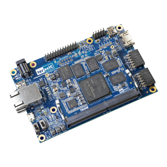
Figure 2-2 shows a photograph of the TSoM Evaluation Kit (TSoM module board and TSOM Based Board). It depicts the layout of the board and indicates the location of the connectors and key components. Figure 2-1 TSoM Evaluation Kit (Top View) www.terasic.com... -
Page 7: Block Diagram
Figure 2-2 TSoM Evaluation Kit (Back View) Figure 2-3 is the block diagram of the TSoM Evaluation Kit and Figure 2-4 shows the block diagram of the TSoM Module board Figure 2-3 Block diagram of the TsoM evaluation kit www.terasic.com... - Page 8 Figure 2-4 Block diagram of the TSoM Module Detailed information about TSoM module and TSOM based board are listed below. TSoM Module FPGA: Cyclone V SE 5CSEBA6U23I7NDK (110K LEs) Interface: DDR4 Edge (include 3.3V power source) Dimension: 50 mm x 70 mm ...
- Page 9 System: Power source: 5V DC on-board USB Blaster II DDR4 socket for TSOM installation FPGA Fabric: LED x 2, Key x 2, Switch x 2 HDMI TX v1.4, 1080P Full-HD, Compatible with HDCP v1.4 ...
-
Page 10: Chapter 3 System Interface
Figure 3-1). It means that when the TSoM evaluation kit is power on, the FPGA is configured from the HPS fabric. When the software on the HPS is running, the FPGA can be configured via HPS. Figure 3-1 TsoM module is setting to FPPx32 mode... - Page 11 Figure 3-2 Boot device for HPS on the TsoM evaluation kit As described in section 3.1 of the TSoM module manual, the SD card shares the same HPS data bus as the eMMC flash. Therefore, only one of these two storage devices can be used to boot HPS at the same time.
-
Page 12: Configuration Of Cyclone V Soc Fpga On Tsom Evalu-Ation Kit
Figure 3-4 QSPI flash/SD Card select switch(Setting to SD Card ) Also, if the user wants to the FPGA is configured by EPCS on TSoM evaluation kit when power on. Then refer to section 3.1 of the TSoM module manual for EPCS part. Modify the SW2 on the... - Page 13 The information is retained within EPCS64 even if the TSoM evaluation kit board is turned off. When the board is powered on, the configuration data in the EPCS64 device is automatically loaded into the Cyclone V SoC FPGA.
- Page 14 If it is not already turned on, turn on the DE-SoC [USB-1] option under currently selected hardware and click “Close” to close the window. See Figure 3-8. Figure 3-8 Hardware Setting Return to the Quartus II programmer and click “Auto Detect”, as circled in Figure 3-9. www.terasic.com TSoM Evaluation Kit User Manual July 26, 2019...
- Page 15 “OK” to close the window, as circled in Figure 3-10. Figure 3-10 Select 5CSEBA6 device Both FPGA and HPS are detected, as shown in Figure 3-11. www.terasic.com TSoM Evaluation Kit User Manual July 26, 2019...
- Page 16 Figure 3-11 FPGA and HPS detected in Quartus programmer Right click on the FPGA device and open the .sof file to be programmed, as highlighted in Figure 3-12. www.terasic.com TSoM Evaluation Kit User Manual July 26, 2019...
- Page 17 Figure 3-13 Select the .sof file to be programmed into the FPGA device Click “Program/Configure” check box and then click “Start” button to download the .sof file into the FPGA device, as shown in Figure 3-14. www.terasic.com TSoM Evaluation Kit User Manual July 26, 2019...
- Page 18 Figure 3-14 Program .sof file into the FPGA device Configure the FPGA in AS Mode The TSoM evaluation kit board uses a serial configuration device (EPCS64) to store configuration data for the Cyclone V SoC FPGA. This configuration data is automatically loaded from the serial configuration device chip into the FPGA when the board is powered up.
-
Page 19: Board Status Elements
Illuminate when data is transferred from FT232R to USB Host. RXD1 UART RXD Illuminate when data is transferred from USB Host to FT232R. There are two HPS reset buttons on TSoM evaluation kit, HPS (cold) reset and HPS warm reset, as shown in Figure 3-17. - Page 20 Figure 3-17 HPS cold and warm reset buttons on TSoM evaluation kit Table 3-2 Description of Two HPS Reset Buttons on TSoM evaluation kit Board Reference Signal Name Description Button1(TSoM Cold reset to the HPS, Ethernet PHY and USB host device.
-
Page 21: Hps Fabric Components
Chapter 4 HPS Fabric Components This chapter describes the interfaces connected to TSoM Based Board. Users can access these interfaces via the HPS processor on the TSoM module. The board supports a RJ-45 connector, which is provided by the TsoM Based Board. -
Page 22: Usb Otg Connector
The board has an USB interfaces (using the SMSC USB3300 controller), which is provided by TsoM Based Board. A SMSC USB3300 device in a 32-pin QFN package device is used to interface to a single Type AB Micro-USB connector. This device supports UTMI+ Low Pin Interface (ULPI) to communicate to USB 2.0 controller in HPS. -
Page 23: Uart To Usb
Table 4-3 The pin assignment of USB OTG PHY to HPS on the TsoM module Signal Name HPS Pin No. Description I/O Standard HPS_USB_CLKOUT G4 Reference Clock Output 3.3V HPS_USB_DATA[1] HPS_USB_DATA[1] 3.3V HPS_USB_DATA[1] HPS_USB_DATA[1] 3.3V HPS_USB_DATA[2] HPS_USB_DATA[2] 3.3V HPS_USB_DATA[3] HPS_USB_DATA[3] 3.3V... -
Page 24: Micro Sd Card
3.3V The board supports Micro SD card interface with x4 data lines. It serves not only an external storage for the HPS on the TsoM module, but also an alternative boot option for the board. Figure 4-4 shows signals connected between the HPS, 260 Pin edge connector and Micro SD card socket. -
Page 25: Raspberry Pi 2X13 Gpio
Cyclone V SoC HPS. It also come with It also comes with two DC +5V (VCC5), two DC +3.3V (VCC3P3), and five GND pins. Figure 4-6 Figure 4-7 shows I/O distribution of the www.terasic.com TSoM Evaluation Kit User Manual July 26, 2019... - Page 26 HPS such as the SPI and UART interfaces. Table 4-7 shows all the pin assignments of the Raspberry Pi 2x13 GPIO header. Figure 4-6 Raspbery Pi 2x13 expansion header www.terasic.com TSoM Evaluation Kit User Manual July 26, 2019...
- Page 27 PIN_81 PIN_C17 RPI GPIO Connection 0 3.3V RPI_GPIO11 PIN_79 PIN_A18 RPI GPIO Connection 0 3.3V RPI_GPIO14 PIN_93 PIN_B16 RPI GPIO Connection 0 3.3V RPI_GPIO15 PIN_91 PIN_C19 RPI GPIO Connection 0 3.3V www.terasic.com TSoM Evaluation Kit User Manual July 26, 2019...
- Page 28 PIN_95 PIN_B19 RPI GPIO Connection 0 3.3V RPI_GPIO24 PIN_97 PIN_C16 RPI GPIO Connection 0 3.3V RPI_GPIO25 PIN_89 PIN_H17 RPI GPIO Connection 0 3.3V RPI_GPIO27 PIN_71 PIN_A20 RPI GPIO Connection 0 3.3V www.terasic.com TSoM Evaluation Kit User Manual July 26, 2019...
-
Page 29: Fpga Fabric Components
Components This section describes the interfaces connected to the FPGA. Users can control or monitor different interfaces with user logic from the FPGA. The TSoM Based Board has two push-buttons connected to the FPGA, as shown in Figure 5-1. Schmitt trigger circuit is implemented and act as switch debounce in... -
Page 30: User Push-Buttons, Switches And Leds
LEDs and Cyclone V SoC FPGA. Table 5-1, Table 5-2 Table 5-3 list the pin assignment of user push-buttons, switches, and LEDs. Figure 5-4 Connections between the LEDs and the Cyclone V SoC FPGA www.terasic.com TSoM Evaluation Kit User Manual July 26, 2019... -
Page 31: Tmd Header
I/O distribution of the TMD connector. The maximum power consumption allowed for a daughter card connected to one or two TMD ports is shown in Table 5-4 Table 5-5, shows all the pin assignments of the TMD connectors. www.terasic.com TSoM Evaluation Kit User Manual July 26, 2019... -
Page 32: A/D Converter And Analog Input
PIN_AD10 TMD1 IO[4] 3.3V PIN_252 TMD1_IO5 TMD1 IO[5] 3.3V PIN_254 PIN_AE9 TMD1_IO6 TMD1 IO[6] 3.3V PIN_258 PIN_V11 TMD1_IO7 TMD1 IO[7] 3.3V PIN_260 PIN_W11 The TsoM Based Board has an analog-to-digital converter (LTC2308). www.terasic.com TSoM Evaluation Kit User Manual July 26, 2019... - Page 33 More information about the A/D converter chip is available in its datasheet. It can be found on manufacturer’s website or in the directory \Datasheet\ADC of TSoM Based Board system CD. Figure 5-7 Connections between the FPGA, 2x5 header, and the A/D converter...
-
Page 34: Hdmi Tx Interface
Video Data bus 3.3-V HDMI_TX_D7 PIN_187 PIN_AH2 Video Data bus 3.3-V HDMI_TX_D8 PIN_191 PIN_AE4 Video Data bus 3.3-V HDMI_TX_D9 PIN_193 PIN_AF4 Video Data bus 3.3-V HDMI_TX_D10 PIN_197 PIN_AE7 Video Data bus 3.3-V www.terasic.com TSoM Evaluation Kit User Manual July 26, 2019... - Page 35 Clock Input Audio Left/Right HDMI_LRCLK PIN_212 PIN_Y8 Channel Signal 3.3-V Input I2S Audio Clock HDMI_SCLK PIN_210 PIN_W8 3.3-V Input I2C_SCL PIN_218 PIN_T8 I2C Clock 3.3-V I2C_SDA PIN_216 PIN_U9 I2C Data 3.3-V www.terasic.com TSoM Evaluation Kit User Manual July 26, 2019...
-
Page 36: Examples For Fpga
A set of built-in video patterns and audio serial data will be sent to the HDMI transmitter to drive the HDMI display with speaker. Users can hear the beeping sound from the speaker when SW0 is set to 1 on the TSoM board. The resolution can be switched by pressing KEY1. System Block Diagram Figure 6-1 shows the system block diagram of this reference design. - Page 37 Figure 6-2 I2S standard audio with 16-bit per channel If users want to modify the frequency of audio output, the register value at register 0x15 has to be modified according to the document ADV7513_Programming_Guide_R0.pdf. The I2S standard www.terasic.com TSoM Evaluation Kit User Manual July 26, 2019...
- Page 38 Demonstration Setup and Instructions Please make sure both Quartus Prime and USB-Blaster II driver are installed on the host Connect the TSoM board to the LCD monitor through a HDMI cable. Power on the TSoM board ...
-
Page 39: Ddr3_Rtl
Figure 6-4. The SW0 is used to enable/disable the sound output on the TSoM board. When you switch the SW0 button to an upper position, you will hear a "beep" sound from the speaker of the HDMI display. Figure 6-4 The video pattern in the HDMI TX demonstration This demonstration performs a memory test function for DDR3 on the TSoM evaluation kit. - Page 40 Quartus Prime v17.1 Demonstration Source Code: Project Directory: Demonstration\FPGA\DDR3 Bit Stream: DDR3\output_files\TSOM_top.sof Demonstration Batch File: Demo Batch File Folder: DDR3\demo_batch The demo batch file includes following files: www.terasic.com TSoM Evaluation Kit User Manual July 26, 2019...
- Page 41 Make sure both Quartus Prime and USB-Blaster II driver are installed on the host PC. Connect TSoM evaluation kit to the host PC via USB cable. Install the USB-Blaster II driver if necessary. Power on the TSoM evaluation kit.
-
Page 42: Programming The Epcs Device
The FPGA should be set to AS x1 mode i.e. MSEL[4..0] = “10010” to use the EPCS as a FPGA configuration device. Note that the factory default mode is FPPx32 mode(MSEL[4:0]= "01010"). User can set the SW2 of the TSoM module to change the MSEL[4:0] to ASx1 mode as shown in Figure 7-1 Figure 7-1 SW2 Setting Resistors (AS Mode) www.terasic.com... - Page 43 1. Choose Convert Programming Files from the File menu of Quartus II. 2. Select JTAG Indirect Configuration File (.jic) from the Programming file type field in the dialog of Convert Programming Files. www.terasic.com TSoM Evaluation Kit User Manual July 26, 2019...
- Page 44 6. Click on the SOF data in the section of Input files to convert. 7. Click Add File. 8. Select the .sof to be converted to a .jic file from the Open File dialog. www.terasic.com TSoM Evaluation Kit User Manual July 26, 2019...
- Page 45 9. Click Open and the Convert Programming Files page will appear. www.terasic.com TSoM Evaluation Kit User Manual July 26, 2019...
- Page 46 10. Click on the Flash Loader and click Add Device. 11. The Select Devices page will appear, please select the targeted FPGA to be programed into the EPCS. www.terasic.com TSoM Evaluation Kit User Manual July 26, 2019...
- Page 47 12. Click OK and the Convert Programming Files page will appear. www.terasic.com TSoM Evaluation Kit User Manual July 26, 2019...
- Page 48 2. Choose Programmer from the Tools menu and the Chain.cdf window will appear. 3. Click Auto Detect and then select the correct device (5CSEBA6). Both FPGA device and HPS should be detected www.terasic.com TSoM Evaluation Kit User Manual July 26, 2019...
- Page 49 4. Double click the red rectangle region shown in below and the "Select New Programming File" page will appear. Select the .jic file to be programmed. 5. Program the EPCS device by clicking the corresponding Program/Configure box. A factory www.terasic.com TSoM Evaluation Kit User Manual July 26, 2019...
- Page 50 SFL image will be loaded. 6. Click Start to program the EPCS device. www.terasic.com TSoM Evaluation Kit User Manual July 26, 2019...
- Page 51 4. Click Auto Detect, and then select correct device, both FPGA device and HPS will detected. 5. Double click the red rectangle region shown in below, and the Select New Programming File page will appear. Select the correct .jic file. www.terasic.com TSoM Evaluation Kit User Manual July 26, 2019...
- Page 52 6. Erase the EPCS device by clicking the corresponding Erase box. A factory default SFL image will be loaded. www.terasic.com TSoM Evaluation Kit User Manual July 26, 2019...
- Page 53 7. Click Start to erase the EPCS device. www.terasic.com TSoM Evaluation Kit User Manual July 26, 2019...
-
Page 54: Emmc Programming
Chapter 8 eMMC Programming This guide will show you how to program the Linux image into the eMMC device on the TSoM module and explain how to update device tree and zImage in the eMMC device. Re-flash linux image to emmc memory 1. - Page 55 6. Make sure that SW1 on the TSoM is switch to the "ON" position, which represents the HPS boot from the SD Card. 7. Connect the PC and TSoM evaluation kit via mini USB cable and connect the Power adapter to power on the board.
- Page 56 9. Press the CPU KEY1(WARM_RST) button on the TSoM module and wait for the "Hit any key to stop autoboot :5" to appear in the Putty window. Press any key to enter uboot. www.terasic.com TSoM Evaluation Kit User Manual July 26, 2019...
- Page 57 10. Enter the command "fatls mmc 0:1" to view the contents of the sdcard fat partition. 11. Enter the command "fatload mmc 0:1 $loadaddr tsom_emmc_168M.img" to load the .img file into the DDR3. 12. Switch SW1 to "OFF" position to switch to eMMC boot mode. www.terasic.com TSoM Evaluation Kit User Manual July 26, 2019...
- Page 58 13. Enter the command "mmc rescan" to rescan the eMMC device. 14. Enter the command "mmc write $loadaddr 0 0x510e0" to program image file to the eMMC device. www.terasic.com TSoM Evaluation Kit User Manual July 26, 2019...
- Page 59 512 bytes size. The size of the image file here is 169984000 bytes , i.e. 169984000/ 512=332000 (block) . 332000 converted to hexadecimal is 0x510e0. 16. Press the COLD_RST button of the TSoM evaluation kit to reboot the board into linux. When the "login in" message appears that shows the programming eMMC success.
- Page 60 Update Device Tree and zImage in the eMMC 1. Before you update files to the eMMC, you should make sure the Tsom board can boot from eMMC correctly. 2. Copy your new device tree file(.dtb) and zImage files to USB flash drive.
- Page 61 7. Press the COLD_RST button to reboot TSoM board, then it will boot linux with your new updated files. www.terasic.com TSoM Evaluation Kit User Manual July 26, 2019...
-
Page 62: Appendix
Appendix Version Change Log V1.0 Initial Version (Preliminary) V1.1 Modify ch3 , ch7 and ch8 according rev B version Copyright © Terasic Inc. All rights reserved. www.terasic.com TSoM Evaluation Kit User Manual July 26, 2019...
Need help?
Do you have a question about the TSoM and is the answer not in the manual?
Questions and answers