Table of Contents
Advertisement
Quick Links
Advertisement
Table of Contents

Related Manuals for Textron Keithley System SourceMeter 2601B-PULSE


Summary of Contents for Textron Keithley System SourceMeter 2601B-PULSE
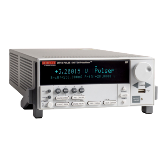
- Page 1 Model 2601B-PULSE System SourceMeter Instrument ® Quick Start Guide...
-
Page 2: Safety Precautions
Safety precautions overvoltages often associated with local AC mains connections. Certain Keithley measuring instruments may be connected to mains. These instruments will be marked as category II The following safety precautions should be observed before using this product and any or higher. - Page 3 Do not touch any object that could provide a current path to the common side of the circuit under The WARNING heading in the user documentation explains hazards that might result test or power line (earth) ground. Always make measurements with dry hands while standing on in personal injury or death.
- Page 4 Power and environmental ratings For indoor use only. Region maximums: 10 A at 20 V Pulser feature output, region 4 Maximum pulse width: 1.8 ms 100 V ac to 240 V ac, 50 Hz to 60 Hz Power supply Maximum duty cycle: 1% (autosensing) Measurement category O Measurement...
- Page 5 Introduction The Model 2601B-PULSE System SourceMeter ® 10 μs Software for the 2601B-PULSE is also available for Pulser/SMU Instrument with PulseMeter™ technology is download from the Keithley web page at tek.com/keithley. an industry-leading high current, high speed pulser with You can search for the specific software you need. Available measure capabilities and the full functionality of a traditional software includes: source-measure unit (SMU).
-
Page 6: Unpack And Inspect The Instrument
Unpack and inspect the instrument Software and documentation downloads document (not shown) To unpack and inspect the instrument: Model 2601B-PULSE System SourceMeter Instrument 1. Inspect the box for damage. Quick Start Guide (this document; not shown) 2. Open the top of the box. 3. -
Page 7: Connect The Instrument
Connect the instrument • Cover the device under test (DUT) to protect the operator from flying debris in the event of a system or DUT failure. Important test system safety information • Make sure any test fixture connected to the system protects the operator from contact with hazardous This product is sold as a stand-alone instrument that may voltages, hot surfaces, and sharp objects. -
Page 8: Install The Instrument
Install the 2601B‑P‑INT NOTE The 2601B-PULSE is shipped with the 2601B-P-INT To keep users safe, always read and follow all safety warnings Rear-Panel Interlock and Cable Connector Box. The provided with each of the instruments in your system. 2601B-P-INT provides connections for an optional hardware safety interlock and simplifies test connections to the 2601B-PULSE. -
Page 9: Wiring The Interlock
3. On the 2601B-P-INT terminal strip panel, use needle- nose pliers to position the INTERLOCK jumper. Place it in the ENABLE slot if you are using an interlock or in the DISABLE slot if you are not using the interlock. Interlock 4. -
Page 10: Connect Line Power
Connect line power CAUTION The 2601B-PULSE operates from a line voltage of 100 V Operating the instrument on an incorrect line voltage to 240 V at 50 Hz or 60 Hz. Line voltage is automatically may cause damage to the instrument, possibly voiding sensed (there are no switches to set). -
Page 11: Turn On The Instrument
Turn on the instrument Power-up sequence When the instrument is turned on, you should see: Turn on the instrument by pressing the front-panel POWER switch to the on (|) position. • A series of dots. • All segments of the display light. •... -
Page 12: Test The Instrument
Test the instrument Step 1: Set source function, range, and level 1. Press the SRC key. You will see a blinking character in the SrcA value field. Confirm that mV is displayed; if The following test verifies basic operation of the not, press the SRC key again. - Page 13 5. Turn the navigation wheel to set the source value to Step 3: Set measurement function and range 20.0000 V, and then press the navigation wheel 1. Press the MEAS key until the V (voltage) enter the selection and exit EDIT mode. measurement function is selected.
- Page 14 To use the pulser feature, you must have remote Step 4: Turn the output on communications set up. Refer to the Model Turn the output on by pressing the OUTPUT ON/OFF 2601B-PULSE Reference Manual (document number control . The ON/OFF indicator LED lights and 2601B-PULSE-901-01) for information on remote measurements begin.
-
Page 15: Next Steps
FAQs Next steps Where can I find updated drivers or firmware? For more information, refer to the Keithley Instruments website, tek.com/keithley, for support and additional For the latest drivers and additional support information, see information about the instrument, including the Model the Keithley Instruments support website. - Page 16 Contact information: 1-800-833-9200 For additional contacts, see https://www.tek.com/contact-us Find more valuable resources at TEK.COM. Copyright © 2020, Tektronix. All rights reserved. Tektronix products are covered by U.S. and foreign patents, issued and pending. Information in this publication supersedes that in all previously published material.
Need help?
Do you have a question about the Keithley System SourceMeter 2601B-PULSE and is the answer not in the manual?
Questions and answers