Advertisement
Quick Links
Chipsmall Limited consists of a professional team with an average of over 10 year of expertise in the distribution
of electronic components. Based in Hongkong, we have already established firm and mutual-benefit business
relationships with customers from,Europe,America and south Asia,supplying obsolete and hard-to-find components
to meet their specific needs.
With the principle of "Quality Parts,Customers Priority,Honest Operation,and Considerate Service",our business
mainly focus on the distribution of electronic components. Line cards we deal with include
Microchip,ALPS,ROHM,Xilinx,Pulse,ON,Everlight and Freescale. Main products comprise
IC,Modules,Potentiometer,IC Socket,Relay,Connector.Our parts cover such applications as commercial,industrial,
and automotives areas.
We are looking forward to setting up business relationship with you and hope to provide you with the best service
and solution. Let us make a better world for our industry!
Contact us
Tel: +86-755-8981 8866 Fax: +86-755-8427 6832
Email & Skype: info@chipsmall.com Web: www.chipsmall.com
Address: A1208, Overseas Decoration Building, #122 Zhenhua RD., Futian, Shenzhen, China
Advertisement

Subscribe to Our Youtube Channel
Related Manuals for Textron Greenlee 5878


Summary of Contents for Textron Greenlee 5878
- Page 1 Chipsmall Limited consists of a professional team with an average of over 10 year of expertise in the distribution of electronic components. Based in Hongkong, we have already established firm and mutual-benefit business relationships with customers from,Europe,America and south Asia,supplying obsolete and hard-to-find components to meet their specific needs.
- Page 2 Lire attentivement et bien comprendre toutes les instructions et les informations sur la sécurité de ce manuel avant d’utiliser ou de procéder à l’entretien de cet outil. 99932857 © 2009 Greenlee Textron Inc. IM 1423 REV 2 3/09...
- Page 3 Do not discard this product or throw away! For recycling information, go to www.greenlee.com. All specifications are nominal and may change as design improvements occur. Greenlee Textron Inc. shall not be liable for damages resulting from misapplication or misuse of its products.
- Page 4 5878 • 5880 • 5882 Important Safety Information SAFETY ALERT SYMBOL This symbol is used to call your attention to hazards or unsafe practices which could result in an injury or property damage. The signal word, defined below, indicates the severity of the hazard. The message after the signal word provides information for preventing or avoiding the hazard.
- Page 5 Important Safety Information Electric shock hazard: • Do not expose this unit to rain or moisture. • Do not use the unit if it is wet or damaged. • Use test leads or accessories that are appropriate for the application. Refer to the category and voltage rating of the test lead or accessory.
- Page 6 5878 • 5880 • 5882 Important Safety Information Electric shock hazard: • Shut off and lock out power. Make sure that all capacitors are discharged. Voltage must not be present. • Set the selector and connect the test leads so that they correspond to the intended measurement. Incorrect settings or connections can result in a blown fuse.
-
Page 7: Table Of Contents
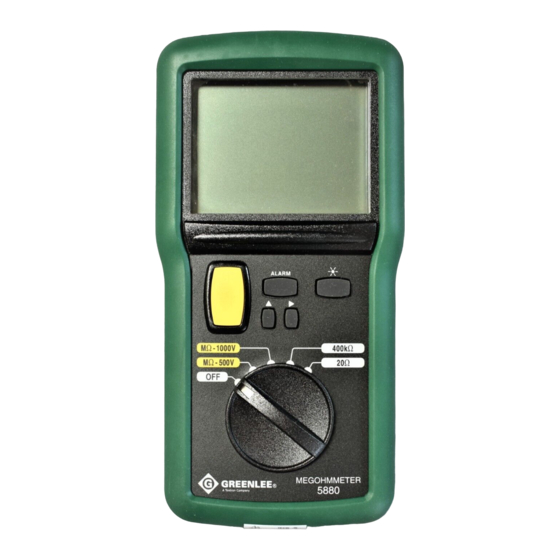
Identification All Models 1. Positive (+) Input Terminal 2. Negative (–) Input Terminal 3. Display 4. Insulation Resistance Test Button 5. Selector Models 5880 and 5882 Only 6. Alarm Button 7. u Select a Parameter or Value 8. p Change the Value 9. -
Page 8: Identification
5878 • 5880 • 5882 Identification (cont’d) Display Icons 11. – Polarity indicator Insulation resistance test in progress 13. t Insulation resistance is less than 50 kΩ 14. y Bar graph element 15. u Insulation resistance is greater than 2 GΩ Timer is active 17. - Page 9 Identification (cont’d) Other Symbols Insufficient battery power (flashing) Lead resistance is compensated incorrectly Replace the fuse ---- Insulation resistance is less than: • 50 kΩ on the 250 V range • 100 kΩ on the 500 V range • 200 kΩ on the 1000 V range Symbols on the Unit Warning—Read the instruction manual Fuse Double insulation Battery Recycle product in accordance with manufacturer’s directions...
- Page 10 5878 • 5880 • 5882 Using the Features Insulation Resistance Measurement Test Button (Yellow Button) Press to apply the test voltage to the item to be tested. Release to terminate the test. • While the yellow insulation resistance test button is pressed, the will appear on the display.
-
Page 11: Display
Using the Features (cont’d) 5. Use the readings to calculate the DAR (dielectric absorption rate): DAR = measurement after 1 minute measurement after 30 seconds 6. Use the readings to calculate the PI (polarization index): PI = measurement after 10 minutes measurement after 1 minute The following parameters indicate acceptable insulation: DAR >... -
Page 12: Insulation Resistance Test Button
5878 • 5880 • 5882 Indicators The Indicator Table provides information for interpreting the battery status indicator, results of the insulation test, and the tones produced by the speaker. Indicator Table Feature Indication Explanation No display Good battery. Battery life is limited. Flashing Battery Status*... - Page 13 Operation Electric shock hazard: Contact with live circuits could result in severe injury or death. Electric shock hazard: Do not contact the test lead tips while the continuity function (20 Ω) is selected. Failure to observe this warning could result in severe injury or death. 1.
- Page 14 5878 • 5880 • 5882 Typical Measurements Insulation Resistance Test 1. Set the selector to the appropriate MΩ – voltage range: • MΩ – 250 V • MΩ – 500 V • MΩ – 1000 V 2. Connect the + lead to the ground and the – lead to the test point. After connection, the megohmmeter automatically will measure the voltage of the item under test.
-
Page 15: Models 5880 And 5882 Only
Typical Measurements Continuity Check 1. Set the selector to the 20 Ω position. 2. Connect the test leads across the device to be tested. 3. The display indicates the resistance of the circuit or component, or OL if the resistance is greater than 20 Ω. -
Page 16: Timer
5878 • 5880 • 5882 Accuracy Accuracy is specified as follows: ± (a percentage of the reading + a fixed amount) at 20 °C to 26 °C (68 °F to 78.8 °F), 45% to 55% relative humidity. Accuracy Table Value Range Accuracy Notes... - Page 17 Specifications Display: 3-1/2-digit LCD (3999 maximum reading) and 35-segment bar graph Sampling Rate: Numeric Display: 2.5 per second Bar Graph Display: 10 per second Automatic Power-Off: After 5 minutes of inactivity Temperature Coefficient: ± (2% + 2 d*) per 10 °C over 26° C or under 20 °C Operating Conditions: 0 °C to 31 °C (32 °F to 88 °F), 0% to 80% relative humidity (non-condensing) 31 °C to 40 °C (88 °F to 104 °F), relative humidity decreasing linearly from 80% to 50%...
- Page 18 Statement of Conformity Greenlee Textron Inc. is certified in accordance with ISO 9001 (2000) for our Quality Management Systems. The instrument enclosed has been checked and/or calibrated using equipment that is traceable to the...
- Page 19 Maintenance Battery and Fuse Replacement Electric shock hazard: Before opening the case, remove the test leads from the circuit and shut off the unit. Failure to observe this warning could result in severe injury or death. Electric shock hazard: The fuse is an integral part of the overvoltage protection. When fuse replacement is necessary, refer to “Specifications’...
- Page 20 Para información sobre reciclaje, visite www.greenlee.com. Todas las especificaciones son nominales y pueden cambiar conforme tengan lugar mejoras de diseño. Greenlee Textron Inc. no se hace responsable de los daños que puedan surgir de la mala aplicación o mal uso de sus productos.
- Page 21 Importante Información sobre Seguridad SÍMBOLO DE ALERTA SOBRE SEGURIDAD Este símbolo se utiliza para indicar un riesgo o práctica poco segura que podría ocasionar lesiones o daños materiales. Cada uno de los siguientes términos denota la gravedad del riesgo. El mensaje que sigue a dichos términos le indica cómo puede evitar o prevenir ese riesgo. Peligros inmediatos que, de no evitarse, OCASIONARÁN graves lesiones o incluso la muerte.
- Page 22 5878 • 5880 • 5882 Importante Información sobre Seguridad Peligro de electrocución: • No exponga esta unidad ni a la lluvia ni a la humedad. • No utilice esta unidad si se encuentra mojada o dañada. • Utilice cables de prueba y accesorios que sean apropiados para la aplicación que se va a realizar.
- Page 23 Importante Información sobre Seguridad Peligro de electrocución: • Desconecte y bloquee la energía. Asegúrese de que todos los condensadores estén totalmente sin carga. No debe haber tensión alguna. • Coloque el interruptor de selección y conecte los cables de prueba de modo que correspondan al tipo de medición que se desea efectuar.
- Page 24 5878 • 5880 • 5882 Identificación Todos los modelos 1. Terminal de entrada positiva (+) 2. Terminal de entrada negativa (-) 3. Pantalla 4. Botón de verificación de resistencia de aislamiento 5. Interruptor de selección Modelos 5880 y 5882 únicamente 6.
- Page 25 Identificación (continuación) Iconos de la pantalla 11. – Indicador de polaridad Verificación de resistencia de aislamiento en progreso 13. t La resistencia de aislamiento es menor de 50 kΩ 14. y Elemento de gráfico de barras 15. u La resistencia de aislamiento es mayor de 2 GΩ El temporizador está...
- Page 26 5878 • 5880 • 5882 Identificación (continuación) Otros símbolos Potencia de pila insuficiente (parpadeante) La resistencia del cable de prueba ha sido incorrectamente compensada Reemplace el fusible ---- La resistencia de aislamiento es menor de: • 50 kΩ en la escala de 250V • 100 kΩ en la escala de 500V • 200 kΩ en la escala de 1.000V Símbolos en la unidad Advertencia —...
Need help?
Do you have a question about the Greenlee 5878 and is the answer not in the manual?
Questions and answers