Table of Contents
Advertisement
Quick Links
Advertisement
Table of Contents

Subscribe to Our Youtube Channel
Related Manuals for Textron GREENLINE 920XC Series


Summary of Contents for Textron GREENLINE 920XC Series
- Page 1 fiber TOOLS ™ 920XC Training 920XC Handheld OTDR Training Presentation VER 1.0...
- Page 2 OTDR Basic Operation Laser End of fiber Probe pulse Display Processor Coupler Fiber Rayleigh Fresnel under test backscatter reflection Detector The Optical Time Domain Reflectometer (OTDR) is an instrument that uses the inherent backscattering properties of an optical fiber to detect faults and categorize its condition. The OTDR sends high-power pulses of laser light down the fiber and captures the light that is reflected back (much like a radar system).
-
Page 3: Dynamic Range
Dynamic Range The measure of a system’s ability to distinguish signals in the presence of noise. Several definitions exist for OTDR dynamic range. Bellcore defines the dynamic range as the displayed attenuation (in dB) from the backscatter level at the front panel to an imaginary line (past the end of the fiber)that lies just above 98% of the noise. - Page 4 Attenuation Deadzone The minimum distance after a reflective event before the OTDR can accurately measure the loss of a non-reflective event. Typically, the attenuation dead zone is the distance from the leading edge of the reflection to the point past the reflection where the OTDR signal level returns to within 0.5 dB of the backscatter level.
- Page 5 Event Deadzone The minimum distance after a reflection before the OTDR can accurately measure the distance to a second reflection, sometimes called the “two point spatial resolution.” The event dead zone is measured from the leading edge of the reflection to the point past the reflection where the level of the OTDR signal drops at least 1.5 dB...
- Page 6 920XC Product Overview Features • Easy to Use/Compact Handheld Design • Automated Measurement/Analysis/File Save • 38dB Dynamic Range • 1.5 meter event deadzone • Large color LCD display • Measure length and defects of coiled fiber • RS-232 and USB interface •...
- Page 7 920XC Measurements Measurement Application • The 920XC instruments display power relating to the distance of returning signals. This information can be used to identify the main properties of an optical fiber chain. Measurement Contents • Event location (distance), end, or rupture of optical fiber chain. •...
- Page 8 920XC - Ports and Indicators Charge Indicator: When lit, measurement power is charging. Power Indicator: When lit, measurement power is on. AC Power Jack: Power adapter jack requirements are 13.8 VDC at 1.2 A. Data Transfer Ports: USB and RS-232 interfaces to transfer saved traces in the instrument to a PC for further analysis with Trace Viewer software (provided).
-
Page 9: Keypad Definitions
Keypad Definitions On/Off: • Press to turn power on or off to the instrument. 2. Run/Stop: • Under GUI, press to start measurement. • While testing, press to stop measurement. 3. Enter: • Under GUI, press to confirm the current operation. •... - Page 10 Keypad Definitions 5. (left and right) arrows • Select parameter to be adjusted in parameter configuration. • Move marker left or right in trace operation. • Turn page while in Help submenu. • Use with the Shift key to zoom out or zoom in trace horizontally. 6.
-
Page 11: Main Display
Main Display... -
Page 12: Measurement Window
Measurement Window Event Finder View Measurement Window Manual Measurement View Instrument Setup View Fiber Analysis View... -
Page 13: Event List
Event List Events • No.: Event sequence number. • Four types of events: . .begin .end; . reflection event; fiber end; attenuation event. • Location: Distance from beginning point to event. • Refl.: Magnitude of reflection. • Ins.L.: Loss of inserted event. •... - Page 14 A & B Markers A & B Markers A marker is used to mark and analyze a single event, trace section, and distance. Distance, attenuation, and loss at a marker or between markers will be displayed in marker information The following parameters are measured between marker A and B.
- Page 15 Measurement Trace Parameters Measurement Trace Parameters • Important measurement and analysis parameters are displayed in the information window . • For definitions and configurations of items (average time, sample distance, range, IOR, wavelength, and pulse width) as well as definitions of item (date, reflection threshold, non- reflection threshold, end threshold, and scattering coefficient), refer to “Setup...
- Page 16 Menu Bar and Icons...
-
Page 17: Setup Parameters
Setup Parameters... - Page 18 Setup – Range Setting Range Setting •Use and to select an adequate range. Press Enter to confirm. Notes: • “Auto” means automatic measurement. When this function is selected, the instrument automatically selects an adequate range and pulse width for the measurement. The process of measurement does not require any intervention by the user.
- Page 19 Setup – Pulsewidth Pulse Width Configuration • The selection of pulse width affects the dynamic range and resolution of the measurement. With a narrow pulse width there will be higher resolution and smaller deadzone; however, the dynamic range will be decreased.
- Page 20 Setup – Avg. Time Averaging Time •Average time will affect the SNR directly. The longer the average time is, the higher SNR is, as well as dynamic range. Therefore, when measuring long-distance optical fiber, a long average time should be selected in order to review events at the long-distance end.
- Page 21 Setup – Wavelength Wavelength Selection • Under the parameter configuration menu use and to highlight “Wavelength.” Press Enter to change the wavelength. • Only on the 920XC...
- Page 22 Setup – Measure Mode Measure Mode • There are two kinds of measurement mode: averaging and real-time. Under real- time mode the 920XC will undertake real- time measurement for the connector of exterior fiber and refurbish the measure trace. While under real-time mode, press Run/Stop to stop;...
- Page 23 Setup – VFL VFL Configuration Under the parameter configuration menu use and to highlight “VFL.” Depending on demand, press Enter to select “CW,” “1Hz,” or “Off.” Press to exit.
- Page 24 Setup – Length Units Length Units • Under the parameter configuration menu use and to highlight “Length Units.” • Press Enter to select the desired units of measurement. • Press to exit.
- Page 25 Setup – IOR Index of Refraction (IOR) Configuration • Because IOR is a key factor affecting the speed of laser transmission in optical fiber, the IOR configuration has a direct impact on the accuracy of measurement. In general, the IOR parameter is provided by the optical fiber manufacturer, and it can be set to the accuracy of four digits after the decimal point between 1.0 .and 2.0.
- Page 26 Setup – Scattering Coefficient Scatter Coefficient Configuration • Scatter coefficient determines the value of backscatter power. This configuration affects the calculation of reflection value. • Under the parameter configuration menu use and to highlight “Scat. Coef.” Press Enter to enter a value. Press to exit.
- Page 27 Setup – Non-Reflective Threshold Non-reflection Threshold Configuration • This configuration has direct impact on the listing of insertion loss events. Only events ≥ to this threshold will be listed. •Under the parameter configuration menu use and to highlight “Nrefl. Thre.” Press Enter ...
- Page 28 Setup – Reflective Threshold Reflection Threshold Configuration • This configuration has direct impact on reflection events listing. Only reflection events ≥ to this threshold will be displayed in the events list. • Under the parameter configuration menu use and to highlight “Refl. Thre.” Press Enter to enter a value.
- Page 29 Setup – End Threshold End Threshold Configuration • This threshold is the end threshold of optical fiber. If the end threshold equals 3.0 dB, then the first event with insertion loss ≥ 3 dB will be considered the end of the optical fiber.
- Page 30 Setup – Delete File Delete File • This function deletes saved traces. • Under the parameter configuration menu use and to highlight “Delete File.” Press Enter to enter. Press to exit. • Use .and to choose the files to delete.
- Page 31 Setup – Time Configuration Time Configuration • Time configuration is used to change system time. • Under the parameter configuration menu use and to highlight “Time (y-m-d).” Press Enter .to change. Press to exit. • Use and to adjust the position of the highlighted area.
- Page 32 Setup – Auto Off Auto Off Configuration • This function conserves battery power. When auto off is enabled, the instrument will automatically power off when idle for 5 minutes. • Under the parameter configuration menu use and to highlight “Auto Off.” Press Enter to switch between “Off”...
-
Page 33: Setup - Language
Setup – Language Language Configuration • There are two language options: English and Chinese. • Under the parameter configuration menu use and to highlight “Lang./ .” Press Enter to .switch the language. Press to exit. - Page 34 Setup – LCD Contrast Adjust Contrast Adjustment of LCD • The contrast of the LCD can be adjusted. • Under the parameter configuration menu use and to highlight “LCD Contrast.” Press Enter to adjust. Press to exit.
- Page 35 Setup – Color Mode Color Mode Setting • This setting changes the color .scheme of the display. • Under the parameter configuration menu use .and to highlight “Color Mode.” Press Enter to choose a different mode. Press to .exit. •...
- Page 36 Setup – Default Setting Default Setting • This function is used to set the OTDR parameters to factory settings. These parameters include: range, pulse width, average time, IOR, non-reflection threshold, reflection threshold, end threshold, and scatter coefficient. • Under the parameter configuration menu use ...
- Page 37 Setup – Help Help • The Help function provides access to the quick reference screen. • Under the parameter configuration menu use and to highlight “Help.” Press Enter to display the quick reference screen. Press to exit.
-
Page 38: Performing A Measurement
Performing a Measurement Quick Reference Screen Initial Splash Screen... - Page 39 Performing a Measurement Setup Connect the optical fiber directly to the 920XC optic output. No tools are required. Clean the connectors. Clean the tie-ins, making sure they are compatible (APC or UPC). Connect optical fiber to the 920XC. • Note: Range is set to “Auto” when auto measurement is on. Auto Trace Measurement Screen while acquiring trace Auto measurement can be used if the length of optical fiber is unknown.
- Page 40 Zoom a Trace Horizontally Zoom out Trace Horizontally To review the details of an event more closely, follow these steps: 1. Under GUI use and to highlight then .press Enter to zoom out the trace horizontally. To zoom out horizontally using the keypad, press Shift + .
- Page 41 Zoom a Trace Vertically Zoom out Trace Vertically To review the details of an event more closely, follow these steps: Under GUI use and to highlight then press Enter to zoom out the trace vertically. To zoom out vertically using the keypad, press Shift + .
- Page 42 Change A & B Marker Reviewing Marker A/B Information Switching between Marker A/B Under GUI use and to highlight , and then press . Enter to switch between marker A/B. Use and to move marker A or B. Information between Marker A/B Under GUI press to ...
- Page 43 Re-analyze a trace Re-analyze a Trace • If the test result at a certain threshold is not adequate, it can be re-analyzed using this function to change the threshold. This function can be effective while the OTDR is disconnected from the fiber. •...
-
Page 44: Save A Trace
Save a Trace Save a Trace When auto or manual measurement is finished, the measurement trace can be saved. The contents of a saved trace include the trace curve and related information of the trace. 1. Under GUI use and to highlight , and then press Enter to enter 2. - Page 45 Browse a Saved Trace Browse a Saved Trace 1. Under GUI use and to highlight , and then press Enter to confirm. 2. Use and to highlight the trace, and then use and to choose “Open”...
- Page 46 Upload a Saved Trace Upload a Saved Trace Saved traces can be uploaded to a PC with the included Trace Viewer software. Then traces can be further processed on a PC. 1. Install the software and run. Refer to Section 7. 2.
-
Page 47: Battery Information
Battery Information •NiMH rechargeable batteries •8 hours continuous operation •20 hours standby operation •User changeable batteries... - Page 48 Battery Information Use of Batteries The 920XC tools use a NiMH battery. Auto Off Mode The instrument will enter auto off mode when there is insufficient power during operation. The low power icon will be displayed on the LCD. If unused for a long time, causing insufficient power, the instrument will enter auto off mode several seconds after powering on in order to protect the batteries in case of excessive discharging.
- Page 49 Battery Information Battery Recharge Status When the 920XC is powered off and powered through the AC/DC adapter, the “CHARGE” indicator on the interface panel will be lit. When the battery is fully recharged, the indicator will turn off. When the instrument is powered on and powered through the AC/DC adapter, the internal battery is automatically recharged.
- Page 50 Maintenance and Replacement of Batteries Maintenance and Replacement of Batteries The 920XC has two batteries: a NiMH battery to power the instrument and a real-time clock (RTC) battery for data retention. Note: Recharge the battery prior to use if the OTDR has not been used for one month.
-
Page 51: Cleaning Interfaces And Connectors
Cleaning Interfaces and Connectors Cleaning Connectors Interfaces must be kept clean. Isopropyl alcohol may be used to clean the optical output. Always replace the protective dust caps when the unit is not being used, and keep the protective dust caps clean. In addition, flanges must be cleaned periodically. -
Page 52: Specifications
Specifications... -
Page 53: Trace Viewer Software
Trace Viewer Software... - Page 54 Trace Viewer Software GUI 1. Menu 2. Tool bar 3. Trace display window (spectral line) 4. Events list window (Events Table) 5. Measurement and analysis parameter window (Parameter Sheet) 6. Fiber information window (fiber section information) 7. Fiber chain information window (fiber chain information) 8.
- Page 55 Menu File (F) The functions enabled under the “File” menu include: upload trace file, open file, save opened file, ASCII format output, printing configuration, printing preview, printing, batch print preview, batch print, batch edit, and exit application. Edit (E) Use the Edit” menu to edit the events list: add event, delete event, and edit optical fiber information.
-
Page 56: Trace Window
Trace Window • The x-axis displays the distance (km); the y-axis represents the backscatter power (dB). • There are two markers, A and B; click either one to activate it. To move the marker, click and drag with the mouse pointer;... -
Page 57: Event Table
Event Table The events list contains the following items: • No.: Sequence of events in optical fiber chain. • Type: Beginning, end, reflection, and non-reflection event. • Distance: Distance from OTDR to event point. • Reflection Value: Value of reflection event. •... -
Page 58: Parameter Window
Parameter Window Parameter Window • The parameter window displays the default parameters of the currently displayed trace. • Measurement parameters include: range, pulse width, average time, and wavelength. • Analysis parameters include: IOR, scattering coefficient, end threshold, non-reflection threshold, reflection threshold, and sampling distance. - Page 59 Marker Information Marker Information Window •This window displays the distance between marker A and B, attenuation coefficient, and loss information. •The two point loss is the difference of vertical power between marker A and B. •Two point attenuation is the two point loss of marker A and B divided by the horizontal distance between marker A and B.
- Page 60 Total Fiber Info Total Fiber Info The contents displayed in this window are date of measurement, length of fiber chain, loss of fiber, attenuation, and event number of fiber.
- Page 61 Upload Trace Data Upload Trace Data • Power off the 920XC • Connect the 920XC to a PC via a serial port cable or USB cable. • Turn the 920XC on and run the 920XC Trace Viewer software. • Under the “File” menu, select “Upload trace file…”, and the “Communications Settings”...
- Page 62 Tool Bar Open file Save file Printing preview Printing Edit optical fiber information Zoom out trace horizontally Zoom in trace horizontally Zoom out trace vertically Zoom in trace vertically Full screen Analyze insertion loss (the five-point measurement to test the insertion loss) Analyze reflectance Lock marker A and B Display version...
-
Page 63: Ascii Format
ASCII Format ASCII Format Output • The Trace Viewer software provides a software interface so that data can be exported in ASCII format and then opened and viewed by a third-party application. • Select “ASCII format output” under the “File” menu. -
Page 64: Edit Optical Fiber Information
Edit Optical Fiber Information Edit Optical Fiber Information • Select “Edit information of optical fiber” under the “Edit” menu to start editing optical fiber information. • Information of optical fiber is a description of measurement trace displayed in the trace window. -
Page 65: Add Event
Add Event Add Event • If an event on the measurement trace is not listed in the events list (due to inaccuracies caused by poor SNR or inadequate parameter configuration), use the “add event” function to manually add this event into the events list. •... - Page 66 Modify Event Modify Event • Use the “revise event” function to manually revise features of an event (due to inaccuracies caused by poor SNR or inadequate parameter configuration). • Select the event to be revised in the events list window, and select “Revise event”. •...
-
Page 67: Delete Event
Delete Event Delete Event • Use the “delete event” function to manually delete a trace from the events list when it appears in error (due to inaccuracies caused by poor SNR or inadequate parameter configuration). • Highlight the event to be deleted, and then select “Delete event” under the “Editing”... -
Page 68: Batch Edit
Batch Edit Batch Edit • The 920XC Trace Viewer software has a batch-edit function that allows users to edit the trace information of several trace files in the same folder at one time. • Select “Batch Edit” under the “File” menu. - Page 69 Printing Printing Options • Select “Printing options…” under the “File” menu to select the contents to be printed. Printing Setup Select “Printing setup” under the “File” menu to select the printer, paper size, and printing orientation.
-
Page 70: Batch Print
Batch Print Batch Print • The 920XC Trace Viewer software has a batch-print function that allows users to print several trace files in the same folder at one time. • Select “Batch Print” under the “File” menu. - Page 71 fiber TOOLS ™ 920XC Handheld OTDR CSR Training...
- Page 72 Why the 920XC? Why is Greenlee launching the 920XC Handheld OTDR? Telecommunications service providers are installing fiber optic networks to deliver high bandwidth service to their customer base. Telecommunications providers require an OTDR to perform cable acceptance testing and fault location on fiber optic networks. There are two main types of networks being deployed by the telecom service provider: ♦FTTN –...
- Page 73 What is an OTDR? Laser End of fiber Probe pulse Display Processor Coupler Fiber Rayleigh Fresnel under test backscatter reflection Detector The Optical Time Domain Reflectometer (OTDR) is an instrument that uses the inherent backscattering properties of an optical fiber to detect faults and categorize its condition. The OTDR sends high-power pulses of laser light down the fiber and captures the light that is reflected back (much like a radar system).
- Page 74 What is cable acceptance testing and fault locating? What is cable acceptance testing? When a fiber is installed by a telecom service provider they are required (typically by the service providers method and practices (procedure) to perform OTDR testing. The OTDR cable acceptance test documents the loss of the fiber span, the length of the cable and the loss of any splices that may be on the fiber cable.
- Page 75 920XC Feature Overview Features • Easy to Use/Compact Handheld Design • Automated Measurement/Analysis/File Save • 38dB Dynamic Range • 1.5 meter event deadzone • Large color LCD display • Measure length and defects of coiled fiber • RS-232 and USB interface •...
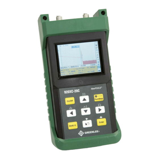
- Page 76 920XC Handheld OTDR USB and RS-232 port Protective Rubber Boot Color LCD with Protective Cover Sealed Membrane OTDR Panel port port...
- Page 77 Specifications...
-
Page 78: Product Configurations
Product Configurations What is the 920XC product configuration? The 920XC has four base models to choose from: Base Model Description 920XC-30F 1310/1550/1625nm OTDR 920XC-30P 1310/1490/1550nm 920XC-20C 1310/1550nm OTDR 920XC-20M 8501300nm Multimode OTDR... -
Page 79: Optical Interfaces
Optical Interfaces OTDR and VFL Interface •PC or APC polish •Ceramic alignment sleeve •Removable adapter for easy cleaning •Protective dust caps •Connector adapters available •FC •ST •SC...
Need help?
Do you have a question about the GREENLINE 920XC Series and is the answer not in the manual?
Questions and answers