Table of Contents

Related Manuals for SEWOO LK-P12


Summary of Contents for SEWOO LK-P12
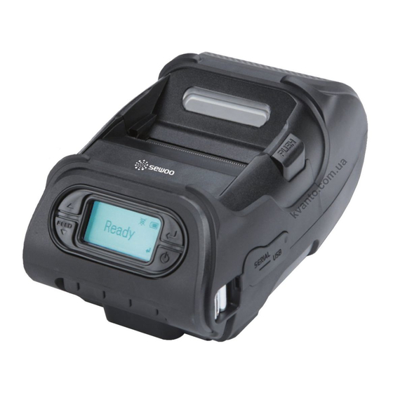
- Page 1 J. STEPHEN Lab., Ltd. 28-6, Gajangsaneopdong-ro, Osan-si, Gyeonggi-do, 18103, Korea TEL : +82-31-8077-5000 FAX : +82-31-459-8880 www.miniprinter.com LK-P12 MODEL: (Peeler) Portable Printer System Administrator Manual P12(Peeler) Rev.C 01/18...
-
Page 2: Table Of Contents
Table of Contents 1. INTRODUCTION 1-1 Using This Manual 1-2 Using the Menu Chart 1-3 Using the Display and Buttons 1-3-1 Selecting a Menu 1-3-2 Exiting a Menu 1-3-3 Printing 1-4. Selecting a Language 2. USING DIAGNOSTICS 2-1 Diagnostics 2-1-1 Printer 2-1-2 Display 2-1-3 Buttons 2-1-4 RAM... - Page 3 4. WI-FI 5. BLUETOOTH 4-1 RF Network 5-1 Using the Bluetooth Settings Dialog 4-2 Wi-Fi setting utility instruction 5-1-1 Enabling the Security 4-2-1 Port and Wi-Fi Information Tab 5-1-2 Changing the Pin 4-2-2 Wi-Fi Information Tab 5-1-3 Local Name 4-2-3 WPA Authentication Tab 5-1-4 Local Address 4-3 Using the Web Interface 5-1-5 Printing Info...
-
Page 4: Introduction
1. INTRODUCTION 1-1. Using This Manual 1-3. Using the Display and Buttons Subjects Contents Introduction Notes before using printer Display Diagnostics How to print test label, check sensor, check print position, etc. How to use the Setting Menu to adjust stock Enter button Up button Setting Up the Printer... -
Page 5: Selecting A Menu
1-4. Selecting a Language 1-3-1. Selecting a Menu You can read Menu names or messages on the printer in English, French, 1. Press the Enter( ) button to enter the Menu. Spanish, German. 2. Move the cursor through the menu using the Up(▲) / Down(▼) buttons, and select an item by pressing the Enter( ) button. -
Page 6: Using Diagnostics
MIF (Monarch Initialization Files) Info. 1. Select Printer - Test Label - Diag Label in Diagnostics Menu (MPCL Only) 1. Turn on the printer. The printer name and software version information is displayed. LK-P12 LK-P12 2. Press the Enter( ) button. - Page 7 **Sensors 3. Select Printer - Test Label - Gray Scale in Diagnostics Menu. In this Menu, you can read each A/D value of the Black Mark and Gap sensor, or Peeler and Peel-SW sensors. The position of each sensor is shown in the following picture.
- Page 8 4. Select Printer – Sensors – Gap in Diagnostics Menu. Check whether the A/D value is 2. Select Printer – Sensors – Black Mark in the Diagnostics Menu. changing in the Gap sensor position by feeding Gap Check whether the A/D value is changing in Black Mark sensor position while feeding stock manually.
-
Page 9: Display
**Printhead 2-1-2. Display In this Menu, You can check Printhead temperature(TPH) in (Centigrade). You can check the display in this Menu. ℃ 1. Select Printer – Printhead – Temperat in the Diagnostics Menu. The temperature of Printhead must be lower than 60℃ to print. Press the Enter( ) button to return to the previous menu. -
Page 10: Buttons
2-1-4. RAM 2-1-3. Buttons Select this Menu and check memory of the printer. 1. Select Keyboard from the Diagnostics Menu. 1. Select RAM in Diagnostics Menu. 2. The message "RAM test running" is displayed. 2. Press the Up(▲) button, press the Down(▼) button, and press the Enter( ) button. 3. - Page 11 2-1-5. Data Dump 2-1-6. About You can see the model name of the printer and H/W and S/W version in this Menu. Use this menu if you are having problems with a data stream. Data Dump captures the data from the communications port and prints that information to a label. 1.
-
Page 12: Setting Up The Printer
3. SETTING UP THE PRINTER 3-1-1. Stock PWR 3-1. SETUP This chapter describes, how to set up the printer. Using this Menu, you can set stock type. This printer uses two kinds of stock types, Standard and High Power. Standard supports tag, label, or receipt stock, and High Power supports linerless and synthetic. -
Page 13: Backlight
3-1-3. Contrast 3-1-2. Backlight This Menu sets the Contrast of the LCD. This Menu activates or deactivates the LCD Backlight. 1. Select Contrast in Setup Menu. 1. In the Setup Menu, select Backlight. 2. Press the Up(▲) button or Down(▼) button to adjust the contrast. 2. -
Page 14: Printer
3-1-4. Printer 4. If you exceed the minimum/maximum range, the following Menu appears and you must set the print contrast within the acceptable range. In this Menu, you can set Print Contrast, Print Positions and use of various sensors. **Adjusting the Supply Position This Menu sets how much the paper is fed during printing. - Page 15 **Adjusting the Margin Adjust **Adjusting the Print Position In this Menu, the printing position can be adjusted left/right based on the value entered. This menu lets you increase or decrease the amount of whitespace above the printed label. 1. Select Setup Menu – Printer – Print Pos. 1.
- Page 16 **Setting the Sensor Mode **Setting the Stock Sensor This Menu allows you to configure the paper sensor according to the type of paper This Menu sets the DAC value for each sensor (Gap, BlackMark). loaded (Gap, BlackMark (BM). 1. Select Setup Menu – Printer – Sensor Mode. 1.
- Page 17 5. The test label will print. Gap Mode 1. With the printer turned off, remove one or two labels from the liner. 2. With the printer in peel mode, place the liner over the sensor. 6. The following message appears. 7.
- Page 18 Black Mark Lower Mode 4. The information label prints. 1. Cover the lower black mark with a label. 5. The following message appears based on the result. 2. Press the Enter( ) button. 6. Press any key to exit from the Menu. 3.
- Page 19 4. The information label prints. Black Mark Upper Mode 1. Cover the upper black mark with a label. The BM Upper sensor is recommended for our supply. 4. Following message appears according to the result. 2. Move to the next step by pressing the Enter( ) button on the following screen.
-
Page 20: Serial Communications
3-1-5. Serial Communications **Baud Rate You can set serial communication using this Menu. 1. Select Setup Menu – Serial Comm – Baud Rate. 2. Select either 1200, 2400, 4800, 9600, 19200, 38400, 57600, or 115200. The following values must be set for serial communication with PC. (※BPS=Bit Per Second) Option Choices... - Page 21 **Data Bits **Flow Control 1. Select Setup Menu – Serial Comm – Data Bits. 1. Select Setup Menu – Serial Comm – Flow Ctrl. 2. Select either 7 Data Bits, or 8 Data Bits. 2. Select No Flow, DTR Flow, RTS flow, Xon/Xoff, or Special. NOTE The “special”...
-
Page 22: Power Management
3-1-6. Power Management 1. Select Setup Menu – Power MGMT -Shut Down This Menu sets the amount of time the printer waits before entering Power Save mode. If a USB cable is connected the printer does not go into Power Save. If the printer goes into Power Save Mode, wake-up the printer by connecting the USB cable, pressing Power( button, or send data to the serial port. -
Page 23: Wi-Fi
1.Turn on the printer by pressing and holding the power button ( ) until the display turns on. 5. If the password is entered correctly, you will see. The printer displays version information. LK-P12 S/W VER. V1.12 CPCL 6. Press the Up(▲)/Down(▼) button to select the Setup menu and press the Enter( ) button. - Page 24 Setting the IP Address **Checking the Printer's Network Status To check the printer’s network status, use this menu. This option sets the printer’s IP address. To exit, press at any time. 1. From the RF Network menu, select Configure. 2. From the Configure menu, select IP Address. Checking the Network Status This option displays the printer’s IP address.
- Page 25 Setting the Power Mode Setting the Subnet Mask This option sets the power mode. This option sets the printer’s subnet mask. 1. From the Configure menu, select Power Mode. 1. From the Configure menu, select Subnet Mask. The choices include CAM (Continuous Awake Mode) or PSP (Power Save Protocol). Use buttons as shown in the following table: PSP conserves battery power.
- Page 26 **Network Information Setting the Protocol You can see the printer's network IP address. This option sets the Protocol. 1. Turn the printer on. 1. From the Configure menu, select Protocol : TCP or LPD. (TCP Fixed) 2. Press ▲ under <T>. You will see the printer’s IP address. For example: 2.
-
Page 27: Wi-Fi Setting Utility Instruction
4-2. Wi-Fi setting utility instruction 4-2-1. Port and Wi-Fi Information Tab Run the configuration utility, and press the ‘Start Wi-Fi Settings’ button as shown Users can connect from a PC to the printer via serial port (COM1 – COM9) or USB port. If the the image below. -
Page 28: Using The Web Interface
4-3. Using the Web Interface 4-3-1. Setting Menu First, set the IP address of the Wi-Fi module so the printer can be accessed on the Figure 2 - Setting Menu network. After setting the IP Address and connecting the user’s PC and the printer to the same network, users can access the printer by entering the IP address into a web browser to access the web-based configuration page. -
Page 29: Ip Setting
4-3-2. IP Setting Figure 4 – IP Setting (DHCP) When IP Setting from Wireless Settings is selected, you will see the figure 3 (Static IP) below, or figure 4 (DHCP) below. You can receive or change the address on this screen. Figure 3 –... -
Page 30: Link Status
4-3-3. Link Status 4-3-4. Site Survey After selecting Link Status from Wireless Settings, users will see the image below. After selecting Site Survey from Wireless Settings, users will see the page below. Through this from this screen, users can check the Module’s current SSID, Mac address, Channel, etc. page, users can see the information for any available APs that are near the module. -
Page 31: Statistics
4-3-5. Statistics 4-3-6. Advance After selecting Statistics From Wireless Settings, users will see a page like the image below. The page shown in figure 8 will show when users choose “Advance” from the “Wireless Setting” This screen shows the current connection statistic by counting the amount of data transmitted menu. -
Page 32: Management
4-3-7. Management 4-3-8. Reboot and Default The page shown in figure 9 will show when users choose “Management” from the “Administration” The page shown in figure 10 will appear when users choose “Reboot and Default” of the menu. Users can set up a user account and change the time settings in this menu. “Administration”... -
Page 33: Upgrade Firmware
4-3-9. Upgrade Firmware 4-3-10. Upload Certificate The page shown in figure 11 will appear when a user chooses “Upload Firmware” from the The page shown in figure 12 will appear when a user chooses “Upload Certificate” from the “Administration” menu. “Administration”... -
Page 34: Status
4-3-11. Status 4-3-12. Statistics The page shown in figure 13 will appear when a user chooses “Status” from the “Administration” The page shown in figure 14 will appear when a user chooses “Statistics” from the “Administration” menu. Users can check the current system information from the module on this page. menu. -
Page 35: Ver. History
4-4. Wi-Fi Glossary 4-3-13. VER. History The page shown in figure 15 will appear when a user chooses “VER. History” from the Access Point An interface between a wireless network and a wired network. Access points can be used with Ethernet “Administration”... - Page 36 EAP (Extensible Authentication Protocol) NIC or Network Interface Card Defines how to pass authentication information between the device and authentication server. The An adapter (board or card) that can be inserted into a device, so the device can be connected to a authentication is handled by the EAP type: FAST, TLS, TTLS, etc.
- Page 37 TKIP (Temporal Key Integrity Protocol) Router Changes the encryption keys regularly and has time limits before new keys are created. Changing the Any device that forwards data along networks. Routers are located at gateways. key periodically provides additional security. Shared Authentication TLS (Transport Layer Security) The access point sends an unencrypted challenge text string to any device attempting to communicate A cryptographic protocol that uses client-side and server-side certificates to authenticate users on the...
-
Page 38: Wi-Fi Specifications
5. Bluetooth 4-5. Wi-Fi Specifications 5-1. Using the Bluetooth Settings Dialog This Menu sets Bluetooth communication. - Frequency 2.4 ~ 2.4835 GHz (US/Canada/Europe), 2.4 ~ 2.497 GHz (Japan) - Communication Rate : 802.11b = 11, 5.5, 2, 1 Mbps 802.11g = 54, 48, 36, 24, 18, 12, 9, 6 Mbps 802.11n(20Mhz) = MCS0-7, up to 72.2 Mbps maximal 802.11n(40Mhz) = MCS0-7, up to 150 Mbps maximal - Channels : USA/Canada: 11 channels... -
Page 39: Changing The Pin
5-1-2. Changing the Pin 5-1-4 Local Address 1. Select Setup Menu – Bluetooth – Change Pin. 1. Select Setup Menu – Bluetooth – Local Address. Local Nam e Local Address 2. The Pin modification screen appears, as shown below. 2. The screen to set Local Name appears as shown below. 3. -
Page 40: Bluetooth Interface
5-2. Bluetooth Interface 5-2-1. Printer Connection Settings You can connect the printer to a PC via serial port (COM1 – COM9) or USB port. When you use a serial port, you have to check the BaudRate setting between the printer & PC. You can change the BaudRate setting of the printer by connecting it to a PC. -
Page 41: Getting Bluetooth Information
5-2-5. Emulation Settings 5-2-2. Getting Bluetooth Information When you click “Get Emulation”, you can see the current emulation setting of the printer. This displays the 12 digit Bluetooth Address. 5-2-3. PIN Code Information You can change the Bluetooth PIN Code by inputting a new PIN Code and pressing “Save Bluetooth PIN Code.”...
Need help?
Do you have a question about the LK-P12 and is the answer not in the manual?
Questions and answers