Table of Contents
Advertisement
Quick Links
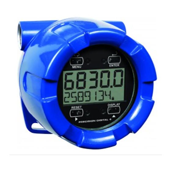
PD6830 EXPLOSION-PROOF
PULSE INPUT RATE/TOTALIZER
Pulse, Open Collector, NPN, PNP, TTL, Switch Contact, Sine Wave
(Coil), Square Wave, Opto-Isolated Inputs
Modern, Sleek and Practical Enclosure
Isolated 4-20 mA Output for Either Rate or Total
5-Digit Rate, 0.7" (17.8 mm)
7 Alphanumeric Character Total/Tag, 0.4" (10.2 mm)
7-Digit Totalizer
SafeTouch
Battery, DC, or Output Loop-Powered Models
Gate Function for Rate Display of Slow Pulse Rates
K-Factor, Scaling, or Live Input Calibration
32-Point Linearization
Password Protection
Backlight Standard on All Models
Explosion-Proof, IP68, NEMA 4X Enclosure
Operates from -40 to 75°C (-20 to 75°C on Battery Models)
PRECISION DIGITAL CORPORATION
89 October Hill Road • Holliston MA 01746 USA
Tel (800) 343-1001 • Fax (508) 655-8990
®
Through-Glass Button Programming
www.predig.com
®
Advertisement
Table of Contents

Related Manuals for PRECISION DIGITAL ProtEX-RTP PD6830


Summary of Contents for PRECISION DIGITAL ProtEX-RTP PD6830
- Page 1 Backlight Standard on All Models Explosion-Proof, IP68, NEMA 4X Enclosure Operates from -40 to 75°C (-20 to 75°C on Battery Models) PRECISION DIGITAL CORPORATION 89 October Hill Road • Holliston MA 01746 USA Tel (800) 343-1001 • Fax (508) 655-8990 www.predig.com...
- Page 2 Disclaimer The information contained in this document is subject to change without notice. Precision Digital makes no representations or warranties with respect to the contents hereof; and specifically disclaims any implied warranties of merchantability or fitness for a particular purpose.
-
Page 3: Introduction
PD6830 Pulse Input Rate/Totalizer Instruction Manual INTRODUCTION The ProtEX-RTP PD6830 is a rugged, explosion-proof pulse input rate/totalizer fully featured for demanding applications in hazardous areas or in the harshest ® environmental conditions. It is programmed using the four SafeTouch through-glass buttons, without removing the cover. -
Page 4: Table Of Contents
PD6830 Pulse Input Rate/Totalizer Instruction Manual Table of Contents INTRODUCTION ---------------------------------------------------------------------- 3 ORDERING INFORMATION ------------------------------------------------------- 3 SPECIFICATIONS -------------------------------------------------------------------- 6 General ------------------------------------------------------------------------------------------- 6 Rate Input ---------------------------------------------------------------------------------------- 7 Rate/Totalizer ----------------------------------------------------------------------------------- 8 4-20 mA Transmitter Output -------------------------------------------------------------- 9 ... - Page 5 PD6830 Pulse Input Rate/Totalizer Instruction Manual Making Changes to a Password Protected Meter ........38 Disabling Password Protection ..............39 Advanced Features Menu ---------------------------------------------------------------- 40 Advanced Features Menu & Display Messages ........41 Indication (INDICAT) .................. 42 ...
-
Page 6: Specifications
PD6830 Pulse Input Rate/Totalizer Instruction Manual SPECIFICATIONS Except where noted all specifications apply to operation at +25°C. General DISPLAY Five digits rate 0.7" (17.8 mm) high, 7-segment, (-9999 to 99999) automatic lead zero blanking. Seven characters 0.4" (10.2 mm) high, 14 segment, Total and/or Tag automatic lead zero blanking. -
Page 7: Rate Input
PD6830 Pulse Input Rate/Totalizer Instruction Manual ENVIRONMENTAL Operating temperature range: -40 to 75°C (-20° to 75°C on battery powered models) Storage temperature range: -40 to 75°C Relative humidity: 0 to 90% non-condensing CONNECTIONS Screw terminals accept 12 to 22 AWG wire ENCLOSURE Explosion-proof die cast aluminum with glass window, corrosion resistant epoxy coating, color: blue. -
Page 8: Rate/Totalizer
PD6830 Pulse Input Rate/Totalizer Instruction Manual LOW-FLOW CUTOFF 0-99999 (0 disables cutoff function) DECIMAL POINT Up to five decimal places or none: d. d ddd, d. d dd, d. d d, d. d , dddddd CALIBRATION May be calibrated using K-Factor, scale without signal source, internal calibration, or by applying an external calibration signal. -
Page 9: 4-20 Ma Transmitter Output
PD6830 Pulse Input Rate/Totalizer Instruction Manual 4-20 mA Transmitter Output OUTPUT Rate or total SOURCE SCALING RANGE 4.000 to 20.000 mA for any display range. CALIBRATION Factory Calibrated: 0.0 to 1000.0 = 4-20 mA output UNDERRANGE Output Underrange: 3.8 mA OVERRANGE Display Overrange: 22.0 mA Output Overrange: 20.5 mA... -
Page 10: Product Ratings And Approvals
PD6830 Pulse Input Rate/Totalizer Instruction Manual Product Ratings and Approvals Class I, Division 1, Groups B, C, D Class II, Division 1, Groups E, F, G Class III, Division 1; T6 Class I, Zone 1, AEx d IIC T6 Gb Zone 21, AEx tb IIIC T85°C Ta = -40°C to +75°C Enclosure: Type 4X &... -
Page 11: Electromagnetic Compatibility
PD6830 Pulse Input Rate/Totalizer Instruction Manual Electromagnetic Compatibility EN 61326:2006 EMISSIONS Safety requirements for measurement, control, and laboratory use – Industrial Group 1 Class A ISM emissions requirements Class A Radiated Emissions EN 61326:2006 IMMUNITY Safety requirements for measurement, control, and laboratory use ±4 kV contact, ±8 kV air... -
Page 12: Installation
PD6830 Pulse Input Rate/Totalizer Instruction Manual INSTALLATION For Installation in USA: The PD6830 must be installed in accordance with the National Electrical Code (NEC) NFPA 70. For Installation in Canada: The PD6830 must be installed in accordance with the Canadian Electrical Code CSA 22.1. For European Community: The PD6830 must be installed in accordance with the ATEX directive 94/9/EC and the product certificate Sira 10ATEX116X. -
Page 13: Mounting
PD6830 Pulse Input Rate/Totalizer Instruction Manual Mounting The PD6830 has two slotted mounting flanges that may be used for pipe mounting or wall mounting. Alternatively, the unit may be supported by the conduit using the conduit holes provided. Refer to Mounting Dimensions, page 52 for details. Do not attempt to loosen or remove flange bolts while the meter is in service. -
Page 14: Figure 1. Pd6830 Connector Board
PD6830 Pulse Input Rate/Totalizer Instruction Manual Connections (continued) ISO+ Isolated signal input positive terminal connection. ISO- Isolated signal return/negative terminal connection. Signal input positive terminal connection. Magnetic pickup (coil) signal return/negative terminal connection. Signal return/negative, DC power return/negative, Contact closure reset return/negative terminal connection. -
Page 15: Input Signal Connections
PD6830 Pulse Input Rate/Totalizer Instruction Manual Input Signal Connections Signal connections are made to a barrier terminal mounted in the base of the enclosure. Input level and type are configured using two slide switches on the bottom of the display module as shown in the lower right of the following figures. Power Supply Flowmeter... -
Page 16: Figure 5. Npn Open Collector Input
PD6830 Pulse Input Rate/Totalizer Instruction Manual +3.0 V SENSOR 100 kOhm Internal Pullup INPUT LEVEL INPUT TYPE ISO+ ISO- Figure 5. NPN Open Collector Input Power Supply SENSOR 100 kOhm Internal Pull-Down INPUT LEVEL INPUT TYPE ISO+ ISO- Figure 6. PNP Sensor with External Power +3.0 V SWITCH CONTACT... -
Page 17: Dc Power Connection
PD6830 Pulse Input Rate/Totalizer Instruction Manual DC Power Connection Models configured for DC power (PD6830-A) are provided with a terminal labeled P+ and are wired as shown in Figure 9. Models configured for battery power (PD6830-B) may optionally be connected to DC power and the battery will function as backup power when DC is lost. -
Page 18: 4-20 Ma Transmitter Output Connections
PD6830 Pulse Input Rate/Totalizer Instruction Manual 4-20 mA Transmitter Output Connections Output connections are made to two terminals labeled LP+ and LP-. Connect to an input device such as a remote display or chart recorder as shown in Figure 10. Power 4-20 mA Input Supply... -
Page 19: Battery Replacement
NOTICE: Battery may only be replaced with an original Model PDABAT36D supplied by Precision Digital. Do not recharge battery. Do not replace with used battery. Remove cover and display module and disconnect display module ribbon cable. -
Page 20: Setup And Programming
PD6830 Pulse Input Rate/Totalizer Instruction Manual SETUP AND PROGRAMMING There is no need to recalibrate the meter for frequency in Hz when first received from the factory. The meter is factory calibrated for Hz prior to shipment. The calibration equipment is certified to NIST standards. Overview ®... -
Page 21: Safetouch Buttons
PD6830 Pulse Input Rate/Totalizer Instruction Manual ® SafeTouch Buttons The PD6830 is equipped with four sensors that operate as through-glass buttons so that it can be programmed and operated without removing the cover (and exposing the electronics) in a hazardous area. These buttons can be disabled for security by selecting the LOCK setting on the switch located on the connector board in the base of the enclosure. -
Page 22: Buttons And Display
PD6830 Pulse Input Rate/Totalizer Instruction Manual Buttons and Display MENU RESET Button Description Symbol Status Symbol Menu High Alarm Set MENU RESET Right arrow/Reset Low Alarm Set Up arrow/Max Total Alarm Set Enter/Ack Password Enabled Press the Menu button to enter or exit the Programming Mode at any time. ... -
Page 23: Main Menu Display Functions & Messages
PD6830 Pulse Input Rate/Totalizer Instruction Manual Main Menu Display Functions & Messages The meter displays various functions and messages during setup, programming, and operation. The following table shows the main menu functions and messages in the order they appear in the menu. Display Parameter Action/Setting... - Page 24 PD6830 Pulse Input Rate/Totalizer Instruction Manual Display Parameter Action/Setting dsabl Disable Disable Manual reset Tag/Units Enter the Tag/Units Menu Tag On Enable Tag/Units Disable Tag/Units Tag Off togle Toggle Tag and Total Tag Toggle A out Transmitter Enter Transmitter Output menu Output Rate Rate output...
-
Page 25: Main Menu
PD6830 Pulse Input Rate/Totalizer Instruction Manual Main Menu The main menu consists of the most commonly used functions: Setup, Program, Password, and Service. Press MENU button to enter Programming Mode then press the Up Arrow button to scroll through the main menu. ... -
Page 26: Setting Numeric Values
PD6830 Pulse Input Rate/Totalizer Instruction Manual Setting Numeric Values The numeric values are set using the Right and Up arrow buttons. Press Right arrow to select next digit and Up arrow to increment digit. The digit being changed blinks. Press the Enter/ACK button, at any time, to accept a setting or MENU button to exit without saving changes. -
Page 27: Setting Up The Meter (Setup)
PD6830 Pulse Input Rate/Totalizer Instruction Manual Setting Up the Meter (SETUP) The Setup menu is used to select: Rate and total decimal point position Program menu Rate and total tag display 4-20 mA transmitter output scaling Press the Enter/Ack button to access any menu or press Up arrow button to scroll through choices. -
Page 28: Setting The Decimal Point (Dec. P T)
PD6830 Pulse Input Rate/Totalizer Instruction Manual Setting the Decimal Point (dec. P T) Rate decimal point may be set with up to four decimal places or with no decimal point at all. Total decimal point may be set with up to six decimal places or with no decimal point at all. -
Page 29: Programming The Meter (Prog)
PD6830 Pulse Input Rate/Totalizer Instruction Manual Programming the Meter (PRoG) It is very important to read the following information, before proceeding to program the meter: There is no need to recalibrate the meter for frequency in Hz when first received from the factory. -
Page 30: K-Factor (Factr)
PD6830 Pulse Input Rate/Totalizer Instruction Manual K-Factor (Factr) The meter may be scaled using the K-Factor function. Most flowmeter manufacturers provide this information with the device. Enter the K-Factor (Factr) menu and select the decimal point with highest resolution possible and program the K-Factor value (i.e. -
Page 31: Scaling The Meter (Scale)
PD6830 Pulse Input Rate/Totalizer Instruction Manual Scaling the Meter (SCale) The pulse input can be scaled to display the process variable in engineering units. A signal source is not needed to scale the meter; simply program the inputs and corresponding display values. Figure 12. -
Page 32: Calibrating The Meter (Cal)
PD6830 Pulse Input Rate/Totalizer Instruction Manual Calibrating the Meter (Cal) To scale the meter without a signal source refer to K-Factor (Factr) or Scaling the Meter (SCale) on page 30. The pulse input can be calibrated to display the process in engineering units by applying the appropriate input signal and following the calibration procedure. - Page 33 PD6830 Pulse Input Rate/Totalizer Instruction Manual Error Message (Error) An error message indicates that the calibration or scaling process was not successful. After the error message is displayed, the meter reverts to input 2 during calibration or scaling, allowing the appropriate input signal to be applied or programmed. The error message might be caused by any of the following conditions: Input signal is not connected to the proper terminals or it is connected backwards.
-
Page 34: Setting The Time Base (Tbase)
PD6830 Pulse Input Rate/Totalizer Instruction Manual Setting the Time Base (tbase) The meter calculates rate based on K-Factor and a time base of units per second, minute, hour, or day. Press the Enter/Ack button, at any time, to accept a setting or Menu button to exit without saving changes. -
Page 35: Manual Or Automatic Total Reset Function (T Rst)
PD6830 Pulse Input Rate/Totalizer Instruction Manual Manual or Automatic Total Reset Function (t rST) For manual reset, select PROGRAM t rst man and then next select whether manual reset will be enabled (Enabl) or disabled (dsabl) using the up arrow key and by then pressing the Enter/Ack button to accept. -
Page 36: Setting The Tag Display (Tag)
PD6830 Pulse Input Rate/Totalizer Instruction Manual Setting the Tag Display (tag) The meter can be set to display a combination of seven alphanumeric characters for engineering units (e.g. GALLONS); for identification (e.g. TANK 3); or for dual rate/total units (e.g. GPS/GAL, LPM/LTR, , BPH/BBL). Press Right arrow to select next character and Up arrow to increment character. -
Page 37: Scaling The 4-20 Ma Analog Output (Aout)
PD6830 Pulse Input Rate/Totalizer Instruction Manual Scaling the 4-20 mA Analog Output (Aout) The 4-20 mA analog output (if equipped) can be scaled to provide a 4-20 mA signal for any display range selected for either the rate or the total. No equipment is needed to scale the analog output;... -
Page 38: Setting Up The Password (Passwrd)
PD6830 Pulse Input Rate/Totalizer Instruction Manual Setting Up the Password (PASSWRD) The Password menu is used to program a five-digit password to prevent unauthorized changes to the programmed parameter settings. The lock symbol is displayed to indicate that settings are protected. Locking the Meter Enter the Password menu and program a five-digit password. -
Page 39: Disabling Password Protection
PD6830 Pulse Input Rate/Totalizer Instruction Manual Disabling Password Protection To disable the password protection, access the Password menu and enter the correct password twice, as shown below. The meter is now unprotected until a new password is entered. Enter Password Run Mode 3024. -
Page 40: Advanced Features Menu
PD6830 Pulse Input Rate/Totalizer Instruction Manual Advanced Features Menu To simplify the setup process, functions not needed for most applications are located in the Advanced features menu. Press and hold the MENU button for five seconds to access the Advanced features menu. Press the Enter/Ack button to access any menu or press Up arrow button to scroll through choices. -
Page 41: Advanced Features Menu & Display Messages
PD6830 Pulse Input Rate/Totalizer Instruction Manual Advanced Features Menu & Display Messages The following table shows the Advanced features menu functions and messages in the order they appear in the menu. Display Parameter Action/Setting INDICAT Indication Enter Indication menu Alarm indication Off Alrm Alarm Indication Enter Alarm menu... -
Page 42: Indication (Indicat)
PD6830 Pulse Input Rate/Totalizer Instruction Manual For instructions on how to program numeric values see Setting Numeric Values, page 26. Indication (INDICAT) The Indication menu is used to enable and set up a high or low rate alarm or total set point alarm indication on the screen. -
Page 43: Gate Function (Gate)
PD6830 Pulse Input Rate/Totalizer Instruction Manual Gate Function (Gate) The gate function is used for displaying slow pulse rates. Using the programmable gate, the meter is able to display pulse rates as slow as 1 pulse every 999 seconds (0.001 Hz). The gate function can also be used to obtain a steady display reading with a fluctuating input signal. -
Page 44: Multi-Point Linearization (Linear)
PD6830 Pulse Input Rate/Totalizer Instruction Manual Multi-Point Linearization (LINEAR) Up to 32 linearization points can be selected under the Linear function. The multi- point linearization can be used to linearize the display for non-linear signals such as those from level transmitters used to measure volume in odd-shaped tanks or to convert level to flow using weirs and flumes that require a complex exponent. -
Page 45: Figure 13. Multi-Point Linearization Menu
PD6830 Pulse Input Rate/Totalizer Instruction Manual LINEAR PROGRAM PROGRAM inP 1 dsp 1 0000. 0 DSPLY 1 INP 2 Figure 13. Multi-Point Linearization Menu... -
Page 46: Contact Debounce Filter (Filter)
PD6830 Pulse Input Rate/Totalizer Instruction Manual Contact Debounce Filter (FiLter) The filter function (FiLter) can be used for applications where the meter is set up to count pulses generated by switch contacts. There are two settings, HI (high speed) and LO (low speed). High speed disables the contact debounce filter and allows any pulse of the minimum specified width for the input wired. -
Page 47: Servicing The Meter (Service)
PD6830 Pulse Input Rate/Totalizer Instruction Manual Servicing the Meter (SERVICE) The Service menu is used to access features used for maintenance. It is Select batt to backup the current total into nonvolatile memory and prepare for a battery swap. Once this is selected, the display will flash Chang BATTERY al- lowing up to 5 minutes for battery removal before it will automatically exit the menu and return to run mode. -
Page 48: Operation
PD6830 Pulse Input Rate/Totalizer Instruction Manual OPERATION Front Panel Buttons Operation Button Description Symbol Press to enter or exit Programming Mode or exit Max/Min readings MENU RESET Press to reset total (if enabled) Press to reset Max/Min readings Press to display Max/Min readings alternately Press to acknowledge alarm (if enabled) Press to display Max or Min reading... -
Page 49: Maximum & Minimum Readings (Maximum & Minimum)
PD6830 Pulse Input Rate/Totalizer Instruction Manual Maximum & Minimum Readings (MAXIMUM & MINIMUM) The maximum and minimum (peak & valley) readings reached by the rate are stored in the meter since the last reset or power-up. The meter shows MAXIMUM or MINIMUM to differentiate between run mode and max/min display. -
Page 50: Factory Defaults & User Settings
PD6830 Pulse Input Rate/Totalizer Instruction Manual Factory Defaults & User Settings The following table shows the factory setting for most of the programmable parameters on the meter. Next to the factory setting, the user may record the new setting for the particular application. Model: ______________ S/N: _______________ Date: _________ Parameter... -
Page 51: Troubleshooting
PD6830 Pulse Input Rate/Totalizer Instruction Manual TROUBLESHOOTING The rugged design and the user-friendly interface of the meter should make it unusual for the installer or operator to refer to this section of the manual. If the meter is not working as expected, refer to the recommendations below. Troubleshooting Tips Symptom Check/Action... -
Page 52: Mounting Dimensions
PD6830 Pulse Input Rate/Totalizer Instruction Manual MOUNTING DIMENSIONS All units: inches [mm] Figure 14. Enclosure Dimensions – Front View... -
Page 53: Figure 14. Enclosure Dimensions - Side Cross Section View
PD6830 Pulse Input Rate/Totalizer Instruction Manual Figure 15. Enclosure Dimensions – Side Cross Section View... -
Page 54: Quick User Interface Reference
PD6830 Pulse Input Rate/Totalizer Instruction Manual QUICK USER INTERFACE REFERENCE Pushbutton Function Menu Go to Programming Mode or leave Programming, Advanced Features, and Max/Min Modes. Right Arrow Move to next digit or decimal point position. Reset Total. Up Arrow Move to next selection or increment digit. Go to Max/Min Mode. Enter/Ack Accept selection/value and move to next selection. - Page 55 PD6830 Pulse Input Rate/Totalizer Instruction Manual...
-
Page 56: Ec Declaration Of Conformity
Tamb -40°C to +75°C IEC 61010-1:2001 & EN 61010-1:2001, including Group and National Differences as they apply for AU, CA, US and KR Community Directives: 94/9/EC ATEX Directive 2004/108/EC EMC Directive Name: Jeffrey Peters Company: Precision Digital Corporation Title: President Date: 1/1/2011... - Page 57 PD6830 Pulse Input Rate/Totalizer Instruction Manual NOTES...
- Page 58 PD6830 Pulse Input Rate/Totalizer Instruction Manual NOTES...
- Page 59 PD6830 Pulse Input Rate/Totalizer Instruction Manual NOTES...
- Page 60 PD6830 Pulse Input Rate/Totalizer Instruction Manual How to Contact Precision Digital For Technical Support: Call: (800) 610-5239 or (508) 655-7300 Fax: (508) 655-8990 Email: support@predig.com For Sales Support: Call: (800) 343-1001 or (508) 655-7300 Fax: (508) 655-8990 Email: sales@predig.com ...
Need help?
Do you have a question about the ProtEX-RTP PD6830 and is the answer not in the manual?
Questions and answers