Table of Contents
Advertisement
Quick Links
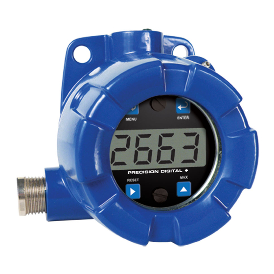
PD663 EXPLOSION-PROOF
LOOP-POWERED METER
4-20 mA input
3½+ Digits LCD, 0.6" High
Easy Four-Button Programming
Programmable Noise Filter
32-Point and Square Root Linearization Input Functions
Max/Min Display
®
HART
Protocol Transparent
Loop-Powered Backlight Option
1.7 V drop (4.7 V with Backlight)
NEMA 4X Enclosure
Operates from -40 to 75°C
PRECISION DIGITAL CORPORATION
89 October Hill Road • Holliston MA 01746 USA
Tel (800) 343-1001 • Fax (508) 655-8990
www.predig.com
Advertisement
Table of Contents

Related Manuals for PRECISION DIGITAL PD663


Summary of Contents for PRECISION DIGITAL PD663
- Page 1 PD663 EXPLOSION-PROOF LOOP-POWERED METER 4-20 mA input 3½+ Digits LCD, 0.6" High Easy Four-Button Programming Programmable Noise Filter 32-Point and Square Root Linearization Input Functions Max/Min Display ® HART Protocol Transparent Loop-Powered Backlight Option ...
- Page 2 Disclaimer The information contained in this document is subject to change without notice. Precision Digital makes no representations or warranties with respect to the contents hereof; and specifically disclaims any implied warranties of merchantability or fitness for a particular purpose.
- Page 3 PD663 Loop-Powered Meter Instruction Manual Limited Warranty Precision Digital Corporation warrants this product against defects in material or workmanship for the specified period under “Specifications” from the date of shipment from the factory. Precision Digital’s liability under this limited warranty shall not exceed the purchase value, repair, or replacement of the defective unit.
-
Page 4: Introduction
The ProtEX-Lite PD663 is a rugged, NEMA 4X loop-powered meter in an explosion-proof enclosure ideal for applications where a simple, inexpensive display is required in a hazardous area. The PD663 is scaled using four push buttons and can be done without applying an actual calibration signal. -
Page 5: Table Of Contents
PD663 Loop-Powered Meter Instruction Manual Table of Contents INTRODUCTION----------------------------------------------------------------------- 4 ORDERING INFORMATION ------------------------------------------------------- 4 SPECIFICATIONS -------------------------------------------------------------------- 7 General ------------------------------------------------------------------------------------------- 7 Input ----------------------------------------------------------------------------------------------- 8 Product Ratings and Approvals---------------------------------------------------------- 9 Electromagnetic Compatibility --------------------------------------------------------- 10 ... - Page 6 PD663 Loop-Powered Meter Instruction Manual Table of Figures Figure 1. PD663 Meter Assembly, Rear View ........14 Figure 2. PD663 Input Connections without Backlight ....15 Figure 3. PD663 Input Connections with Backlight ......15 Figure 4. Enclosure Dimensions – Front View ......... 32 ...
-
Page 7: Specifications
PD663 Loop-Powered Meter Instruction Manual SPECIFICATIONS Except where noted all specifications apply to operation at +25°C. General 0.6" (15.24 mm) LCD, 3½+ digits; -1999 to 2999 DISPLAY 2 Updates/Second DISPLAY UPDATE RATE 2999 Display flashes OVERRANGE -1999 Display flashes UNDERRANGE... -
Page 8: Input
PD663 Loop-Powered Meter Instruction Manual Input ±1 count ACCURACY Linear (2 to 32 points) or square root FUNCTION TEMPERATURE 50 PPM/C from -40 to 75C ambient DRIFT User selectable decimal point DECIMAL POINT Input 1 & Input 2: 0.40 mA... -
Page 9: Product Ratings And Approvals
This information is contained within the serial number with the first four digits representing the year and month in the YYMM format. For European Community: The PD663 must be installed in accordance with the ATEX directive 94/9/EC and the product certificate Sira 10ATEX1116X. -
Page 10: Electromagnetic Compatibility
PD663 Loop-Powered Meter Instruction Manual Electromagnetic Compatibility EN 61326:2006 EMISSIONS Safety requirements for measurement, control, and laboratory use – Industrial Group 1 Class A ISM emissions requirements Radiated Class A Emissions EN 61326:2006 IMMUNITY Safety requirements for measurement, control, and laboratory use ±4 kV contact,... -
Page 11: Safety Information
PD663 Loop-Powered Meter Instruction Manual SAFETY INFORMATION WARNINGS Read complete instructions prior to installation and operation of the meter. Installation and service should be performed only by trained service personnel. Service requiring replacement of internal components must be performed at the factory. -
Page 12: Installation
PD663 Loop-Powered Meter Instruction Manual INSTALLATION For Installation in USA: The PD663 must be installed in accordance with the National Electrical Code (NEC) NFPA 70. For Installation in Canada: Install in accordance with applicable local and national regulations (e.g. NEC). The PD663 must be installed in accordance with the Canadian Electrical Code CSA 22.1. -
Page 13: Mounting
PD663 Loop-Powered Meter Instruction Manual Mounting The PD663 has two mounting holes that may be used for a 1.5” pipe mounting or wall mounting. Alternatively, the unit may be supported by the conduit using the conduit holes provided. It can also be pipe mounted by using the PDA6863 pipe mount kit for 2" pipe. -
Page 14: Figure 1. Pd663 Meter Assembly, Rear View
WARNING Observe all safety regulations. Electrical wiring should be performed in accordance with all agency requirements and applicable national, state, and local codes to prevent damage to the meter and ensure personnel safety. Figure 1. PD663 Meter Assembly, Rear View... -
Page 15: 4-20 Ma Input Connections & Wiring Diagrams
S+ S- X 4-20 mA Transmitter Power Supply Figure 2. PD663 Input Connections without Backlight S+ S- B- 4-20 mA Transmitter Power Supply Figure 3. PD663 Input Connections with Backlight... -
Page 16: Setup And Programming
PD663 Loop-Powered Meter Instruction Manual SETUP AND PROGRAMMING There is no need to recalibrate the meter for milliamps when first received from the factory. The meter is factory calibrated for milliamps prior to shipment. The calibration equipment is certified to NIST standards. -
Page 17: Buttons And Display
PD663 Loop-Powered Meter Instruction Manual Buttons and Display Button/ Description Symbol Menu button to enter programming mode. Press and hold for 5 seconds to access the Advanced features of the meter. MENU Enter button to access a menu or accept a setting. -
Page 18: Setting Numeric Values
PD663 Loop-Powered Meter Instruction Manual Setting Numeric Values The numeric values are set using the Right and Up arrow buttons. Press the Right arrow to select next digit and the Up arrow to increment digit. The two left- most digits on the display are set as a single digit, able to display -19 to 29. -
Page 19: Main Menu
PD663 Loop-Powered Meter Instruction Manual Main Menu The main menu consists of the most commonly used functions: Decimal Point Location, Scale, and Calibration. Press Menu button to enter Programming Mode then press the Up Arrow button to scroll through the main menu. -
Page 20: Main Menu Display Functions & Messages
PD663 Loop-Powered Meter Instruction Manual Main Menu Display Functions & Messages The meter displays various functions and messages during setup, programming, and operation. The following table shows the main menu functions and messages in the order they appear in the menu. -
Page 21: Scaling The Meter (Scl)
PD663 Loop-Powered Meter Instruction Manual Scaling the Meter (SCL) The 4-20 mA input can be scaled to display the process in engineering units. A signal source is not needed to scale the meter; simply program the inputs and corresponding display values. -
Page 22: Calibrating The Meter (Cal)
PD663 Loop-Powered Meter Instruction Manual Calibrating the Meter (Cal) To scale the meter without a signal source refer to Scaling the Meter (SCL), page 21. The meter can be calibrated to display the process in engineering units by applying the appropriate input signal and following the calibration procedure. -
Page 23: Advanced Features Menu
PD663 Loop-Powered Meter Instruction Manual Advanced Features Menu To simplify the setup process, functions not needed for most applications are located in the Advanced features menu. Press and hold the Menu button for five seconds to access the Advanced features menu Run Mode 26. -
Page 24: Advanced Features Menu & Display Messages
PD663 Loop-Powered Meter Instruction Manual Advanced Features Menu & Display Messages The following table shows the Advanced features menu functions and messages in the order they appear in the menu. Display Parameter Action/Setting Set linear or square root input Input Function... -
Page 25: Signal Input Conditioning Function (Fnc)
PD663 Loop-Powered Meter Instruction Manual Signal Input Conditioning Function (Fnc) The PD663 provides linear and squar root signal input conditioning functions for inputs from linear and non-linear transmitters. Linear (Lnr) Meters are set up at the factory for linear function using two-point linearization. -
Page 26: Internal Calibration (Ical)
PD663 Loop-Powered Meter Instruction Manual Internal Calibration (ICal) There is no need to recalibrate the meter for milliamps when first received from the factory. The meter is factory calibrated for milliamps prior to shipment. The calibration equipment is certified to NIST standards. -
Page 27: Operation
PD663 Loop-Powered Meter Instruction Manual OPERATION Front Panel Buttons Operation Button Description Symbol Press to enter or exit Programming Mode or exit Max/Min readings. MENU Press to indefinitely display Max or Min until Menu button is pressed. ENTER Press to reset Max or Min reading. -
Page 28: Maximum & Minimum Readings (Hi & Lo)
PD663 Loop-Powered Meter Instruction Manual Maximum & Minimum Readings (HI & LO) The maximum and minimum (peak & valley) readings reached by the process are stored in the meter since the last reset or power-up. The meter flashes HI or LO to differentiate between run mode and max/min display. -
Page 29: Reset Meter To Factory Defaults
PD663 Loop-Powered Meter Instruction Manual Reset Meter to Factory Defaults When the parameters have been changed in a way that is difficult to determine what’s happening, it might be better to start the setup process from the factory defaults. Instructions to load factory defaults: Enter the Advanced features menu. -
Page 30: Factory Defaults & User Settings
PD663 Loop-Powered Meter Instruction Manual Factory Defaults & User Settings The following table shows the factory setting for most of the programmable parameters on the meter. Next to the factory setting, the user may record the new setting for the particular application. -
Page 31: Troubleshooting
PD663 Loop-Powered Meter Instruction Manual TROUBLESHOOTING The rugged design and the user-friendly interface of the meter should make it unusual for the installer or operator to refer to this section of the manual. If the meter is not working as expected, refer to the recommendations below. -
Page 32: Mounting Dimensions
PD663 Loop-Powered Meter Instruction Manual MOUNTING DIMENSIONS All units: inches [mm] Figure 4. Enclosure Dimensions – Front View... -
Page 33: Figure 5. Enclosure Dimensions - Side Cross Section View
PD663 Loop-Powered Meter Instruction Manual Figure 5. Enclosure Dimensions – Side Cross Section View Note: The supplied conduit plug may extend up to 0.6 in [15 mm] from the conduit opening when installed. -
Page 34: Quick User Interface Reference
PD663 Loop-Powered Meter Instruction Manual QUICK USER INTERFACE REFERENCE Pushbutton Function Go to Programming Mode, leave Programming Mode, and Max/Min Menu Mode. Hold for 5 seconds to access Advanced Features. Right Arrow Move to next digit or decimal point position. Reset Min/Max. -
Page 35: Ec Declaration Of Conformity
Issued in accordance with ATEX Directive 94/9/EC Precision Digital Corporation Manufacturer: 89 October Hill Rd Ste 5 Holliston, MA 01746 USA PD663 Series Process Meter Device: Sira Certification Service, notified body no. 0518 Notified Body: Rake Lane, Eccleston, Chester, CH4 9JN, England... - Page 36 PD663 Loop-Powered Meter Instruction Manual How to Contact Precision Digital For Technical Support please Call: (800) 610-5239 or (508) 655-7300 Fax: (508) 655-8990 Email: support@predig.com For Sales Support or to place an order please contact your local distributor or...
Need help?
Do you have a question about the PD663 and is the answer not in the manual?
Questions and answers