Sign In
Upload
Manuals
Brands
PRECISION DIGITAL Manuals
Measuring Instruments
ProVu PD7000
PRECISION DIGITAL ProVu PD7000 Manuals
Manuals and User Guides for PRECISION DIGITAL ProVu PD7000. We have
2
PRECISION DIGITAL ProVu PD7000 manuals available for free PDF download: Instruction Manual
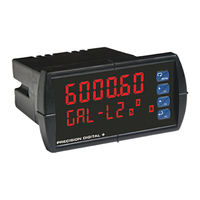
PRECISION DIGITAL ProVu PD7000 Instruction Manual (96 pages)
Temperature Input Meter
Brand:
PRECISION DIGITAL
| Category:
Measuring Instruments
| Size: 1 MB
Table of Contents
Table of Contents
3
Introduction
6
Ordering Information
7
Specifications
8
General
8
Temperature Input
10
Relays
11
Isolated 4-20 Ma Output
11
Modbus ® RTU Serial Communications
12
PDA1044 Digital Input & Output Expansion Module
13
Compliance Information
14
Safety
14
Electromagnetic Compatibility
14
Safety Information
15
Figure 1. 1/8 DIN Panel Cutout Dimensions
16
Mounting Dimensions
17
Installation
16
Unpacking
16
Panel Mounting Instructions
16
Figure 2. Meter Dimensions - Side View
17
Figure 3. Meter Dimensions - Top View
17
Figure 4. Panel Mounting Details
18
Figure 5. Jumper Configuration for 12/24 VDC Power
18
Configuration for 12 or 24 VDC Power Option
18
Connections
19
Connectors Labeling
20
Figure 6. Connector Labeling for Fully Loaded PD7000
20
Figure 7. Power Connections
20
Power Connections
20
Figure 8. Thermocouple Input Connections
21
Signal Connections
21
Figure 10. Two-Wire RTD Input Connections
22
Figure 9. Three-Wire RTD Input Connections
22
Figure 11. Four-Wire RTD Input Connections
23
Figure 12. Average Temperature RTD Input Connections
23
Figure 13. Relay Connections
24
Modbus RTU Serial Communications
24
Relay Connections
24
Figure 14. AC and DC Loads Protection
25
Figure 15. Low Voltage DC Loads Protection
25
Switching Inductive Loads
25
4-20 Ma Output Connections
26
F4 Digital Input Connections
26
Figure 16. F4 Digital Input Connections
26
Figure 17. 4-20 Ma Output Connections
26
Power Supply for Analog Output Loop or Other Uses
26
External Relays & Digital I/O Connections
27
Figure 18. Expansion Modules & DIN Rail Mounting Kit
27
Figure 19. External Relays Module Connections
27
Interlock Relay Feature
28
Connections for Averaging RTD Sensors
23
Figure 20. Digital I/O Module Connections
28
Figure 21. Interlock Connections
28
Setup and Programming
29
Front Panel Buttons and Status LED Indicators
30
Display Functions & Messages
31
Main Menu
34
Setting Numeric Values
35
Model PD7000 Temperature Input Meter
36
Setting up the Meter (Setup)
36
Setting the Input Signal (Input)
38
Selecting the Temperature Scale (F or C)
38
Setting the Decimal Point (Dec Pt)
38
Setting the Display Parameter & Intensity (Dsplay)
38
Display Setup Menu
39
Setting the Input Units or Custom Tags (Units)
40
Setting the Relay Operation (Relay)
41
Setting the Relay Action
43
Programming Set and Reset Points
44
Setting Fail-Safe Operation
44
Programming Time Delay
44
Relay Action for Loss of Input (Input Break)
44
Meterview ® Pro Software
45
Relay and Alarm Operation Diagrams
46
High Alarm Operation (Set > Reset)
46
Low Alarm Operation (Set < Reset)
47
High Alarm with Fail-Safe Operation (Set > Reset)
48
Low Alarm with Fail-Safe Operation (Set < Reset)
49
Relay Alternation Control Operation
50
Relay Sampling Operation
51
Signal Loss or Input Break Relay Operation
52
Time Delay Operation
53
Relay Operation Details
54
Fail-Safe Operation
54
Overview
54
Relays Auto Initialization
54
Front Panel Leds
55
Latching and Non-Latching Relay Operation
55
Latching Relay (Latch)
56
Non-Latching Relay (A-Nman)
56
Non-Latching Relay (Auto)
56
Acknowledging Relays
57
Figure 22. Acknowledge Relays W/Function Key or Digital Input
57
Latching Relay (Lt-Clr)
57
Setting up the Interlock Relay (Force On) Feature
58
Scaling the 4-20 Ma Analog Output (Aout)
59
Reset Menu (Reset)
60
Control Menu (Contrl)
60
Setting up the Password (Pass)
61
Protecting or Locking the Meter
61
Making Changes to a Password Protected Meter
62
Disabling Password Protection
62
Model PD7000 Temperature Input Meter
63
Advanced Features Menu
63
Advanced Features Menu & Display Messages
64
Offset Adjust (Adjust)
67
Recalibration of the Meter (T CAL)
67
Noise Filter (Filter)
69
Noise Filter Bypass (Bypass)
69
Rounding Feature (Round)
69
Modbus RTU Serial Communications (Serial)
70
Select Menu (Select)
71
Analog Output Programming (Aoutpr)
72
Programmable Function Keys User Menu (User)
73
Internal Temperature Calibration (ICAL)
74
Meter Copy Function (Copy)
77
Figure 23. Meter Copy Connection
77
Meter Operation
79
Front Panel Buttons Operation
79
Function Keys Operation
79
F4 Operation
80
Maximum/Minimum Readings
80
Troubleshooting
81
Diagnostics Menu (Diag)
81
Determining Software Version
81
Reset Meter to Factory Defaults
82
Factory Defaults & User Settings
83
Troubleshooting Tips
86
Alphabetical List of Display Functions & Messages
87
Figure 24: 1/8 DIN Panel Cutout Template
91
Advertisement
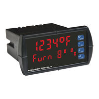
PRECISION DIGITAL ProVu PD7000 Instruction Manual (40 pages)
Temperature Meter
Brand:
PRECISION DIGITAL
| Category:
Measuring Instruments
| Size: 2 MB
Table of Contents
Table of Contents
3
Introduction
6
Ordering Information
6
Specifications
7
General
7
Temperature Input
8
Relays
8
Isolated 4-20 Ma Output
9
USB Connection
9
On-Board Digital Input (F4)
9
Modbus ® RTU Serial Communications
9
Meterview Pro
9
Compliance Information
10
Safety
10
Electromagnetic Compatibility
10
Safety Information
10
Installation
10
Unpacking
10
Panel Mounting Instructions
11
Mounting Dimensions
11
Figure 1: 1/8 DIN Panel Cutout and Mounting
11
Figure 2. Meter Dimensions - Side View
11
Figure 3. Meter Dimensions - Top View
11
Installation Overview
12
Meterview Pro Software
12
Meterview Pro Installation
12
Connections
13
Connectors Labeling
13
Power Connections
13
Figure 4. PD7000-##0 Connectors Label
13
Figure 5. PD7000-##2 Connectors Label
13
Figure 6. PD7000-##3 Connectors Label
13
Figure 7. PD7000-##4 Connectors Label
13
Figure 8. PD7000-##5 Connectors Label
13
Figure 9. PD7000-##7 Connectors Label
13
Figure 10. Power Connections
13
Signal Connections
14
Connections for Averaging RTD Sensors
14
Modbus RTU Serial Communications
14
Figure 11. Thermocouple Input Connections
14
Figure 12. Three-Wire RTD Input Connections
14
Figure 13. Two-Wire RTD Input Connections
14
Figure 14. Four-Wire RTD Input Connections
14
Figure 15. Average Temperature RTD Input Connections
14
Relay Connections
15
Switching Inductive Loads
15
F4 Digital Input Connections
15
Ma Output Connections
15
Analog Output Power Supply
15
Figure 16. Relay Connections
15
Figure 17. AC and DC Loads Protection
15
Figure 18. Low Voltage DC Loads Protection
15
Figure 19. F4 Digital Input Connections
15
Figure 20. 4-20 Ma Output Connections
15
External Relays & Digital I/O Connections
16
Interlock Relay Feature
16
Figure 22. Expansion Module & DIN Rail Mounting Kit
16
Figure 23. External Relays Module Connections
16
Figure 24. Digital I/O Module Connections
16
Figure 25. Interlock Connections
16
Setup and Programming
17
Front Panel Buttons and Status LED Indicators
17
Display Functions & Messages
18
Main Menu
19
Setting Numeric Values
20
Setting up the Meter (Setup)
20
Setting the Input Signal (Input)
20
Selecting the Temperature Scale (F or C)
20
Setting the Decimal Point (Dec Pt)
20
Setting the Display Parameter & Intensity (Dsplay)
21
Display Intensity (D-Inty)
21
Setting the Display Units or Custom Tags (Units)
21
Setting the Relay Operation (Relay)
22
Setting the Relay Action
22
Programming Set and Reset Points
23
Setting Fail-Safe Operation
23
Programming Time Delay
23
Relay Action for Loss of Input (Input Break)
23
Relay and Alarm Operation Diagrams
23
High Alarm Operation (Set > Reset)
23
Low Alarm Operation (Set < Reset)
23
High Alarm with Fail-Safe Operation (Set > Reset)
24
Low Alarm with Fail-Safe Operation (Set < Reset)
24
Relay Sampling Operation
24
Signal Loss or Input Break Relay Operation
24
Time Delay Operation
25
Relay Operation Details
25
Overview
25
Relays Auto Initialization
25
Fail-Safe Operation
25
Front Panel Leds
26
Latching and Non-Latching Relay Operation
26
Non-Latching Relay (Auto)
26
Non-Latching Relay with Manual Reset (A-Nman)
26
Latching Relay (Latch)
26
Latching Relay with Clear (Lt-Clr)
27
Acknowledging Relays
27
Setting up the Interlock Relay (Force On) Feature
27
Scaling the 4-20 Ma Analog Output (Aout)
28
Reset Menu (Reset)
28
Manual Control Menu (Contrl)
28
Setting up the Password (Pass)
29
Protecting or Locking the Meter
29
Making Changes to a Password Protected Meter
29
Disabling Password Protection
29
Advanced Features Menu
30
Advanced Features Menu & Display Messages
30
Offset Adjust (Adjust)
31
Recalibration of the Meter (T CAL)
31
Noise Filter (Filter)
31
Noise Filter Bypass (Bypass)
32
Rounding Feature (Round)
32
Modbus RTU Serial Communications (Serial)
32
Select Menu (Select)
32
Analog Output Programming (Aoutpr)
32
Programmable Function Keys User Menu (User)
33
Internal Temperature Calibration (ICAL)
34
Meter Operation
35
Front Panel Buttons Operation
35
Function Keys Operation
35
F4 Operation
35
Maximum/Minimum Readings
35
Troubleshooting
36
Diagnostics Menu (Diag)
36
Determining Software Version
36
Reset Meter to Factory Defaults
36
Factory Defaults & User Settings
37
Troubleshooting Tips
38
EU Declaration of Conformity
39
Advertisement
Related Products
PRECISION DIGITAL PROVU PD7000-6R0
PRECISION DIGITAL PROVU PD7000-7R0
PRECISION DIGITAL PROVU PD7000-6R2
PRECISION DIGITAL PROVU PD7000-7R2
PRECISION DIGITAL PROVU PD7000-6R3
PRECISION DIGITAL PROVU PD7000-7R3
PRECISION DIGITAL PROVU PD7000-6R4
PRECISION DIGITAL PROVU PD7000-7R4
PRECISION DIGITAL PROVU PD7000-6R5
PRECISION DIGITAL PROVU PD7000-7R5
PRECISION DIGITAL Categories
Measuring Instruments
Controller
Monitor
Scanner
Test Equipment
More PRECISION DIGITAL Manuals
Login
Sign In
OR
Sign in with Facebook
Sign in with Google
Upload manual
Upload from disk
Upload from URL