PRECISION DIGITAL ProVu Series Instruction Manual
Temperature input meter
Hide thumbs
Also See for ProVu Series:
- Instruction manual (96 pages) ,
- Quick start manual (8 pages) ,
- Instruction manual (56 pages)
Table of Contents
Advertisement
Quick Links
PD7000 Temperature Input Meter
•
J, K, T, E, R, S, B, N, C Thermocouples
•
100 or 1000 Ω Platinum, 10 Ω Copper, 120 Ω Nickel RTDs
•
1° or 0.1° Resolution
•
Averages up to 10 RTD Sensors
•
Automatic Cold Junction Compensation
•
NEMA 4X, IP65 Front
•
Universal 85-265 VAC, or 12/24 VDC Input Power Models
•
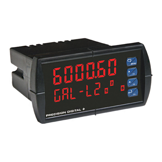
Large Dual-Line 6-Character Display, 0.60" & 0.46"
•
Sunlight Readable Display Models
•
Programmable Display & Function Keys
•
2 or 4 Relays + Isolated 4-20 mA Output Options
•
External 4-Relay & Digital I/O Expansion Modules
•
USB, RS-232, RS-485 Serial Communication Options
®
•
Modbus
RTU Protocol Standard
•
Configure, Monitor, and Datalog from a PC with
Free MeterView
PRECISION DIGITAL CORPORATION
89 October Hill Road • Holliston MA 01746 USA
Tel (800) 343-1001 • Fax (508) 655-8990
Instruction Manual
®
Pro Software
www.predig.com
Advertisement
Table of Contents
Troubleshooting

Related Manuals for PRECISION DIGITAL ProVu Series


Summary of Contents for PRECISION DIGITAL ProVu Series
- Page 1 ® • Modbus RTU Protocol Standard • Configure, Monitor, and Datalog from a PC with ® Free MeterView Pro Software PRECISION DIGITAL CORPORATION 89 October Hill Road • Holliston MA 01746 USA Tel (800) 343-1001 • Fax (508) 655-8990 www.predig.com...
- Page 2 Anyone using this product for such applications does so at his/her own risk. Precision Digital Corporation shall not be held liable for damages resulting from such improper use.
-
Page 3: Table Of Contents
Model PD7000 Temperature Input Meter Instruction Manual Table of Contents INTRODUCTION ------------------------------------------------------------ 6 ORDERING INFORMATION --------------------------------------------- 7 SPECIFICATIONS ---------------------------------------------------------- 8 General ------------------------------------------------------------------------------- 8 Temperature Input -------------------------------------------------------------- 10 Relays ------------------------------------------------------------------------------ 11 Isolated 4-20 mA Output ----------------------------------------------------- 11 ® Modbus RTU Serial Communications ---------------------------------- 12 PDA1044 Digital Input &... - Page 4 Model PD7000 Temperature Input Meter Instruction Manual Setting Up the Meter (setup) ------------------------------------------------ 36 Setting the Input Signal (Input) ------------------------------------------ 38 Selecting the Temperature Scale (F or C) ---------------------------- 38 Setting the Decimal Point (dEc pt) -------------------------------------- 38 Setting the Display Parameter & Intensity (dsplay) ----------------- 38 Display Setup Menu --------------------------------------------------------- 39 Setting the Input Units or Custom Tags (units) ---------------------- 40 Setting the Relay Operation (relay) ------------------------------------ 41...
- Page 5 Model PD7000 Temperature Input Meter Instruction Manual Advanced Features Menu ---------------------------------------------------- 63 Advanced Features Menu & Display Messages ---------------------- 64 Offset Adjust (Adjust) ------------------------------------------------------ 67 Recalibration of the Meter (t CAL) --------------------------------------- 67 Noise Filter (filter) -------------------------------------------------------- 69 Noise Filter Bypass (bypass) ---------------------------------------------- 69 Rounding Feature (round) ------------------------------------------------- 69 Modbus RTU Serial Communications (serial) ---------------------- 70 Select Menu (SElect) ------------------------------------------------------- 71...
-
Page 6: Introduction
Model PD7000 Temperature Input Meter Instruction Manual Table of Figures Figure 1. 1/8 DIN Panel Cutout Dimensions ........16 Figure 2. Meter Dimensions - Side View ..........17 Figure 3. Meter Dimensions - Top View ..........17 Figure 4. Panel Mounting Details ............18 Figure 5. -
Page 7: Ordering Information
Model PD7000 Temperature Input Meter Instruction Manual ORDERING INFORMATION Standard Models 85-265 VAC 12/24 VDC Options Installed Model Model PD7000-6R0 PD7000-7R0 No options PD7000-6R2 PD7000-7R2 2 relays (PD1102*) PD7000-6R3 PD7000-7R3 4-20 mA output (PD1103*) PD7000-6R4 PD7000-7R4 4 relays (PD1104*) PD7000-6R5 PD7000-7R5 2 relays &... -
Page 8: Specifications
Model PD7000 Temperature Input Meter Instruction Manual SPECIFICATIONS Except where noted all specifications apply to operation at +25°C. General Upper display: 0.60" (15 mm) high red LEDs; DISPLAY Lower display: 0.46" (12 mm) high red LEDs. Both displays have six characters with leading zero blanking. - Page 9 Installation Overvoltage Category II: CATEGORY Local level with smaller transient overvoltages than Installation Overvoltage Category III. ENVIRONMENTAL ProVu Series (PD7000): Operating temperature range: -40 to 65°C Storage temperature range: -40 to 85°C Relative humidity: 0 to 90% non-condensing ProtEX-MAX (PD8 Series): T6 Class operating temperature range Ta = -40 to 60°C...
-
Page 10: Temperature Input
Model PD7000 Temperature Input Meter Instruction Manual Temperature Input INPUTS Thermocouple: J, K, T, E, R, S, B, N, C; RTD: 100 Ω platinum (0.00385 & 0.00392 coefficients), 10 Ω copper, 120 Ω nickel, 1000 Ω platinum (0.00385 & 0.00392 coefficients) COLD Automatic, fixed, no user calibration needed JUNCTION... -
Page 11: Relays
Model PD7000 Temperature Input Meter Instruction Manual Relays RATING 2 or 4 SPDT (Form C) internal and/or 4 SPST (Form A) external; rated 3 A @ 30 VDC and 125/250 VAC resistive load; 1/14 HP (≈ 50 W) @ 125/250 VAC for inductive loads NOISE Noise suppression is recommended for each relay contact SUPPRESSION... -
Page 12: Modbus ® Rtu Serial Communications
4-20 mA output or other devices.Refer to Figure 6 on page OUTPUT LOOP 20 and Figure 17 on page 26. OR OTHER USES ProVu Series (PD7000): All models rated @ 40 mA max. ProtEX-MAX (PD8 Series): All models @ 25 mA max. -
Page 13: Pda1044 Digital Input & Output Expansion Module
Model PD7000 Temperature Input Meter Instruction Manual PDA1044 Digital Input & Output Expansion Module CHANNELS 4 digital inputs & 4 digital outputs per module SYSTEM Up to 2 modules for a total of 8 inputs & 8 outputs DIGITAL INPUT 3 to 5 VDC LOGIC HIGH DIGITAL INPUT... -
Page 14: Compliance Information
Model PD7000 Temperature Input Meter Instruction Manual COMPLIANCE INFORMATION Safety UL & c-UL LISTED USA & Canada UL 508 Industrial Control Equipment UL FILE NUMBER E160849 FRONT PANEL UL Type 4X, NEMA 4X, IP65; panel gasket provided LOW VOLTAGE EN 61010-1:2001 DIRECTIVE Safety requirements for measurement, control, and laboratory use... -
Page 15: Safety Information
Model PD7000 Temperature Input Meter Instruction Manual Note: Testing was conducted on PD7000 meters installed through the covers of grounded metal enclosures with cable shields grounded at the point of entry representing installations designed to optimize EMC performance. Declaration of Conformity available at www.predig.com SAFETY INFORMATION CAUTION: Read complete WARNING: Risk of... -
Page 16: Installation
Model PD7000 Temperature Input Meter Instruction Manual INSTALLATION There is no need to remove the meter from its case to complete the installation, wiring, and setup. Instructions are provided for setting up a 12/24 VDC powered meter to operate from 12 VDC power, see page 18. Unpacking Remove the meter from box. -
Page 17: Mounting Dimensions
Model PD7000 Temperature Input Meter Instruction Manual Mounting Dimensions Figure 2. Meter Dimensions - Side View Figure 3. Meter Dimensions - Top View... -
Page 18: Configuration For 12 Or 24 Vdc Power Option
Model PD7000 Temperature Input Meter Instruction Manual Gasket Removable Connectors Panel Mounting Mounting Bracket Screw Figure 4. Panel Mounting Details Configuration for 12 or 24 VDC Power Option Warning! Do not exceed voltage rating of the selected configuration. Meters equipped with the 12/24 VDC power option are shipped from the factory ready to operate from 24 VDC. -
Page 19: Connections
Model PD7000 Temperature Input Meter Instruction Manual Connections All connections are made to removable screw terminal connectors located at the rear of the meter. Use copper wire with 60°C or 60/75°C insulation for all line voltage connections. Observe all safety regulations. Electrical wiring should be performed in accordance with all applicable national, state, and local codes to prevent Caution! -
Page 20: Connectors Labeling
Model PD7000 Temperature Input Meter Instruction Manual Connectors Labeling The connectors’ label, affixed to the meter, shows the location of all connectors available with requested configuration. Do not connect any equipment other than Precision Digital’s expansion modules, cables, or meters to the RJ45 M-LINK connector. -
Page 21: Signal Connections
Model PD7000 Temperature Input Meter Instruction Manual Signal Connections Signal connections are made to a three-terminal connector labeled SIGNAL on Figure 6. Thermocouple and RTD Connections The following figures show examples for thermocouple and RTD connections. The TYPE selector switch must be set to the proper position for the meter to accept the selected RTD or TC input. -
Page 22: Figure 9. Three-Wire Rtd Input Connections
Model PD7000 Temperature Input Meter Instruction Manual SIGNAL M-LINK TYPE RANGE Sensor Figure 9. Three-Wire RTD Input Connections The meter accepts two, three, or four-wire RTDs. The three-wire RTD connection has built-in lead wire compensation. SIGNAL M-LINK TYPE RANGE Sensor Figure 10. -
Page 23: Connections For Averaging Rtd Sensors
Model PD7000 Temperature Input Meter Instruction Manual SIGNAL M-LINK TYPE RANGE Sensor Figure 11. Four-Wire RTD Input Connections The four-wire RTD connection is similar to the three-wire. One of the leads of a four-wire RTD is not connected, and may be clipped off. The three-wire connection provides sufficient lead wire compensation to obtain accurate readings even with long leads. -
Page 24: Modbus Rtu Serial Communications
Model PD7000 Temperature Input Meter Instruction Manual Modbus RTU Serial Communications Serial communications connection is made to an RJ45 connector labeled ® M-LINK on Figure 6. For interfacing to the P , use the PDA1232 for RS-232, the PDA1485 for RS-485, or the PDA8008 for USB. The same port is used for interfacing with all expansion modules (i.e. -
Page 25: Switching Inductive Loads
Figure 15. Low Voltage DC Loads Protection RC Networks Available from Precision Digital RC networks are available from Precision Digital and should be applied to each relay contact switching an inductive load. Part number: PDX6901. Note: Relays are de-rated to 1/14th HP (50 watts) with an inductive load. -
Page 26: F4 Digital Input Connections
Model PD7000 Temperature Input Meter Instruction Manual F4 Digital Input Connections A digital input, F4, is standard on the meter. This digital input connected with a normally open closure across F4 and COM, or with an active low signal applied to F4. Figure 16. -
Page 27: External Relays & Digital I/O Connections
Model PD7000 Temperature Input Meter Instruction Manual External Relays & Digital I/O Connections The relay and the digital I/O expansion modules PDA1004 & PDA1044 are connected to the meter using a CAT5 cable provided with each module. The two RJ45 connectors on the expansion modules are identical and interchangeable;... -
Page 28: Interlock Relay Feature
Model PD7000 Temperature Input Meter Instruction Manual DI 1-4 DO 1-4 5 VDC Figure 20. Digital I/O Module Connections Interlock Relay Feature As the name implies, the interlock relay feature reassigns one, or more, alarm/control relays for use as interlock relay(s). Interlock contact(s) are wired to digital input(s) and trigger the interlock relay. -
Page 29: Setup And Programming
Model PD7000 Temperature Input Meter Instruction Manual SETUP AND PROGRAMMING The meter is factory calibrated prior to shipment to read temperature in degrees Fahrenheit. The calibration equipment is certified to NIST standards. Overview There are two switches, located at the back of the meter, to set the input selection for TC or RTD and for 100-ohm platinum or 10-ohm copper. -
Page 30: Front Panel Buttons And Status Led Indicators
Model PD7000 Temperature Input Meter Instruction Manual Front Panel Buttons and Status LED Indicators Button Description Status Symbol Menu Alarm 1-8 indicator Flashing: Relay in Right arrow/F1 1-8-M manual control mode Manual control relays Up arrow/F2 &/or analog output Flashing: Relay Enter/F3 interlock switch open Note:... -
Page 31: Display Functions & Messages
Model PD7000 Temperature Input Meter Instruction Manual Display Functions & Messages The meter displays various functions and messages during setup, programming, and operation. The following table shows the main menu functions and messages in the order they appear in the menu. Display Parameter Action/Setting Description... - Page 32 Model PD7000 Temperature Input Meter Instruction Manual Display Parameter Action/Setting Description Latching Set relay for latching operation LatcH Latching- Set relay for latching operation with manual Lt-CLr cleared reset only after alarm condition has cleared Alternate Set relay for alternation control Altern Set relay for sampling operation Sanmpl...
- Page 33 Model PD7000 Temperature Input Meter Instruction Manual Display Parameter Action/Setting Description Relay goes to non-alarm condition when input break is detected Analog output Enter the Analog output scaling menu Aout Display 1 Program display 1 value Dis 1 Program output 1 value (e.g. 4.000 mA) Out 1 Output 1 Dis 2...
-
Page 34: Main Menu
Model PD7000 Temperature Input Meter Instruction Manual Main Menu The main menu consists of the most commonly used functions: Setup, Reset, Control, and Password. • Press Menu button to enter Programming Mode then press the Up arrow button to scroll main menu. •... -
Page 35: Setting Numeric Values
Model PD7000 Temperature Input Meter Instruction Manual Setting Numeric Values The numeric values are set using the Right and Up arrow buttons. Press Right arrow to select next digit and Up arrow to increment digit value. The digit being changed is displayed brighter than the rest. Press and hold up arrow to auto-increment the display value. -
Page 36: Setting Up The Meter (Setup)
Model PD7000 Temperature Input Meter Instruction Manual Setting Up the Meter (setup) It is very important to read the following information, before proceeding to program the meter: • The meter is factory calibrated prior to shipment to read temperature in degrees Fahrenheit. The calibration equipment is certified to NIST standards. - Page 37 Model PD7000 Temperature Input Meter Instruction Manual...
-
Page 38: Setting The Input Signal (Input)
Model PD7000 Temperature Input Meter Instruction Manual Setting the Input Signal (Input) Enter the Input menu to set up the meter to accept thermocouple ( tc ) or RTD ( rtd ) inputs. The Type selector switch, located at the rear of the meter, must be set accordingly. -
Page 39: Display Setup Menu
Model PD7000 Temperature Input Meter Instruction Manual Display Setup Menu • Press the Up arrow to change selection • Press Enter to accept setting • Press Menu to exit programming After setting up the input and display, press the Menu button to exit programming and skip the rest of the setup menu. -
Page 40: Setting The Input Units Or Custom Tags (Units)
Model PD7000 Temperature Input Meter Instruction Manual Setting the Input Units or Custom Tags (units) Enter the input unit or custom tag that will be displayed if alternating rate, total, or grand total and units is selected in the units menu, or d unit is selected as the Lower display parameter. -
Page 41: Setting The Relay Operation (Relay)
Model PD7000 Temperature Input Meter Instruction Manual Setting the Relay Operation (relay) This menu is used to set up the operation of the relays. During setup, the relays do not follow the input and they will remain in the state found prior to entering the Relay menu. Caution! Relay action Automatic reset only (non-latching) - Page 42 Model PD7000 Temperature Input Meter Instruction Manual...
-
Page 43: Setting The Relay Action
Model PD7000 Temperature Input Meter Instruction Manual Setting the Relay Action Operation of the relays is programmed in the Action menu. The relays may be set up for any of the following modes of operation: Automatic reset (non-latching) Automatic + manual reset at any time (non-latching) Latching (manual reset only, at any time) Latching with Clear (manual reset only after alarm condition has cleared) -
Page 44: Programming Set And Reset Points
Model PD7000 Temperature Input Meter Instruction Manual Programming Set and Reset Points High alarm indication: program set point above reset point. Low alarm indication: program set point below reset point. The deadband is determined by the difference between set and reset points. -
Page 45: Meterview ® Pro Software
Model PD7000 Temperature Input Meter Instruction Manual ® MeterView Pro Software The meter can also be programmed using the PC-based MeterView Pro software available for free download at www.predig.com. Data logging for one meter at the time is available with MeterView Pro software. -
Page 46: Relay And Alarm Operation Diagrams
Model PD7000 Temperature Input Meter Instruction Manual Relay and Alarm Operation Diagrams The following graphs illustrate the operation of the relays, status LEDs, and ACK button. High Alarm Operation (Set > Reset) For Manual reset mode, ACK can be pressed anytime to turn "off" relay. To detect a new alarm condition, the signal must go below the set point, and then go above it. -
Page 47: Low Alarm Operation (Set < Reset)
Model PD7000 Temperature Input Meter Instruction Manual Low Alarm Operation (Set < Reset) Input Reset de-energized energized Relay Automatic (non-latching) Relay pressed Automatic or Manual (non-latching) Relay pressed Manual (latching) Relay pressed Manual only after passing above Reset (latching with clear) For Manual reset mode, ACK can be pressed anytime to turn "off"... -
Page 48: High Alarm With Fail-Safe Operation (Set > Reset)
Model PD7000 Temperature Input Meter Instruction Manual High Alarm with Fail-Safe Operation (Set > Reset) Input Reset de-energized energized Relay Automatic (non-latching) Relay pressed Automatic or Manual (non-latching) Relay pressed Manual (latching) Relay pressed Manual only after passing below Reset (latching with clear) Note: Relay coil is energized in non-alarm condition. -
Page 49: Low Alarm With Fail-Safe Operation (Set < Reset)
Model PD7000 Temperature Input Meter Instruction Manual Low Alarm with Fail-Safe Operation (Set < Reset) Input Reset de-energized energized Relay Automatic (non-latching) Relay pressed Automatic or Manual (non-latching) Relay pressed Manual (latching) Relay pressed Manual only after passing above Reset (latching with clear) Note: Relay coil is energized in non-alarm condition. -
Page 50: Relay Alternation Control Operation
Model PD7000 Temperature Input Meter Instruction Manual... -
Page 51: Relay Sampling Operation
Model PD7000 Temperature Input Meter Instruction Manual Relay Sampling Operation Input Reset Sample Sample Sample Time Time Time Relay When the signal crosses the set point, the relay trips and the sample time starts. After the sample time has elapsed, the relay resets. The cycle repeats every time the set point is crossed, going up for high alarms and going down for low alarms. -
Page 52: Signal Loss Or Input Break Relay Operation
Model PD7000 Temperature Input Meter Instruction Manual Signal Loss or Input Break Relay Operation The following graph shows the input break relay operation for a high alarm relay. Input INPUT BREAK INPUT BREAK Reset de-energized energized Relay Input Break = Ignore Relay Input Break = Off Relay... -
Page 53: Time Delay Operation
Model PD7000 Temperature Input Meter Instruction Manual Time Delay Operation The following graphs show the operation of the time delay function. Input Reset <Tdelay <Tdelay >=Tdelay Relay On Time Delay Input Reset <Tdelay <Tdelay >=Tdelay Relay Off Time Delay When the signal crosses the set point, the On time delay timer starts and the relay trips when the time delay has elapsed. -
Page 54: Relay Operation Details
Model PD7000 Temperature Input Meter Instruction Manual Relay Operation Details Overview The relay capabilities of the meter expand its usefulness beyond simple indication to provide users with alarm and control functions. These capabilities include front panel alarm status LEDs as well as either 2 or 4 optional internal relays and/or 4 external relays expansion module. -
Page 55: Front Panel Leds
Model PD7000 Temperature Input Meter Instruction Manual Front Panel LEDs The LEDs on the front panel provide status indication for the following: Status Status Alarm 1 Alarm 5 Alarm 2 Alarm 6 Alarm 3 Alarm 7 Alarm 4 Alarm 8 The meter is supplied with four alarm points that include front panel LEDs to indicate alarm conditions. -
Page 56: Non-Latching Relay (Auto)
Model PD7000 Temperature Input Meter Instruction Manual Non-Latching Relay (Auto) Automatic reset only Condition Relay Normal Alarm Ack (No effect) Normal In this application, the meter is set up for automatic reset (non-latching relay). Acknowledging the alarm while it is still present has no effect on either the LED or the relay. -
Page 57: Latching Relay (Lt-Clr)
Model PD7000 Temperature Input Meter Instruction Manual Latching Relay (Lt-Clr) Manual reset only after alarm condition has cleared Condition Relay Normal Alarm Ack (No effect) Normal In this application, the meter is set up for manual reset only after the signal passes the reset point (alarm condition has cleared). -
Page 58: Setting Up The Interlock Relay (Force On) Feature
Model PD7000 Temperature Input Meter Instruction Manual Setting Up the Interlock Relay (Force On) Feature Relays 1-4 can be set up as interlock relays. To set up the relays for the interlock feature: 1. Access the Setup – Relay – Action menu and set the action to off. 2. -
Page 59: Scaling The 4-20 Ma Analog Output (Aout)
Model PD7000 Temperature Input Meter Instruction Manual Scaling the 4-20 mA Analog Output (Aout) The 4-20 mA analog output can be scaled to provide a 4-20 mA signal for any display range selected. No equipment is needed to scale the analog output; simply program the display values to the corresponding mA output signal. -
Page 60: Reset Menu (Reset)
Model PD7000 Temperature Input Meter Instruction Manual Reset Menu (reset) The Reset menu is used to reset the maximum or minimum reading (peak or valley) reached by the process; both may be reset at the same time by selecting “reset high & low” ( rst HL ). Control Menu (Contrl) The Control menu is used to control the 4-20 mA analog output and the relays manually, ignoring the input. -
Page 61: Setting Up The Password (Pass)
Model PD7000 Temperature Input Meter Instruction Manual Setting Up the Password (pass) The Password menu is used for programming three levels of security to prevent unauthorized changes to the programmed parameter settings. Pass 1: Allows use of function keys and digital inputs Pass 2: Allows use of function keys, digital inputs and editing set/reset points Pass 3: Restricts all programming, function keys, and digital inputs Protecting or Locking the Meter... -
Page 62: Making Changes To A Password Protected Meter
Model PD7000 Temperature Input Meter Instruction Manual Making Changes to a Password Protected Meter If the meter is password protected, the meter will display the message Locd ( Locked ) when the Menu button is pressed. Press the Enter button while the message is being displayed and enter the correct password to gain access to the menu. -
Page 63: Advanced Features Menu
Model PD7000 Temperature Input Meter Instruction Manual Advanced Features Menu To simplify the setup process, functions not needed for most applications are located in the Advanced Features menu. Press and hold the Menu button for three seconds to access the advanced features of the meter. -
Page 64: Advanced Features Menu & Display Messages
Model PD7000 Temperature Input Meter Instruction Manual Advanced Features Menu & Display Messages The following table shows the functions and messages of the Advanced Features menu in the order they appear in the menu. Display Parameter Action/Setting Adjust Set adjust value to offset temperature Adjust reading T Cal... - Page 65 Model PD7000 Temperature Input Meter Instruction Manual Display Parameter Action/Setting Minimum Program minimum mA output allowed Calibrate Calibrate 4-20 mA output (internal Calib reference source used for scaling the output) 4 mA output Enter mA output value read by milliamp 4 mA meter with at least 0.001 mA resolution 20 mA output...
- Page 66 Model PD7000 Temperature Input Meter Instruction Manual Display Parameter Action/Setting Filter Filter value filter Bypass Bypass value bypass Round Round value round Display Display assignments dsplay Relays Relay settings relay Analog output Analog output scaling Aout Analog output programming Analog output Aout pr programming Serial communication settings...
-
Page 67: Offset Adjust (Adjust)
Model PD7000 Temperature Input Meter Instruction Manual Offset Adjust (Adjust) This parameter allows the user to select an offset adjustment to the temperature being displayed. Offset adjustment values can be either positive or negative and can be any number within ± 50.0 ° F (+27.8 ° C). The offset adjustment value is programmed through the Adjust menu. - Page 68 Model PD7000 Temperature Input Meter Instruction Manual Recommended Calibration Points To recalibrate the meter, it is recommended to use the Fahrenheit scale; this will give a greater degree of accuracy to the calibration. The scale can be changed to the Celsius scale after calibration is completed. The meter will display temperature accurately in any scale.
-
Page 69: Noise Filter (Filter)
Model PD7000 Temperature Input Meter Instruction Manual Set up the meter to display temperature in degrees Fahrenheit. Apply signal corresponding to input 1 (32°F) and program the display to read 32.0. Apply signal corresponding to input 2 (1184°F for type J) and program the display accordingly. -
Page 70: Modbus Rtu Serial Communications (Serial)
Model PD7000 Temperature Input Meter Instruction Manual Modbus RTU Serial Communications (serial) The meter is equipped with serial communications capability as a standard feature using the Modbus RTU Serial Communication Protocol. To communicate with a computer or other data terminal equipment, an RS-232, RS-485, or USB adapter (PDA8008) option is required;... -
Page 71: Select Menu (Select)
Model PD7000 Temperature Input Meter Instruction Manual Select Menu (SElect) The Select menu is used to program the analog output parameters. There are no other selections for this model. -
Page 72: Analog Output Programming (Aoutpr)
Model PD7000 Temperature Input Meter Instruction Manual Analog Output Programming (AoutPr) The Analog Output Programming menu is used to program the behavior of the 4-20 mA output. The following parameters and functions are programmed in this menu: Source: Source for generating the 4-20 mA output (e.g. PV - temperature) Overrange: Analog output value with display in overrange condition Underrange: Analog output value with display in underrange condition... -
Page 73: Programmable Function Keys User Menu (User)
Model PD7000 Temperature Input Meter Instruction Manual Programmable Function Keys User Menu (user) The User menu allows the user to assign the front panel function keys F1, F2, F3, digital input F4 and up to eight digital inputs to access most of the menus or to activate functions immediately (e.g. -
Page 74: Internal Temperature Calibration (Ical)
Model PD7000 Temperature Input Meter Instruction Manual Internal Temperature Calibration (ICAL) The meter is factory calibrated prior to shipment to read temperature in degrees Fahrenheit. The calibration equipment is certified to NIST standards. The Internal Calibration ( ICAL ) is a function used at the factory to calibrate all the thermocouple and RTD ranges. - Page 75 Model PD7000 Temperature Input Meter Instruction Manual Thermocouple Input Internal Calibration (ICAL) Set the Type selector switch in the TC position and using copper wire connect a precision mV calibrator to the input. In the Setup menu select the input: TC – Type J. Press and hold the Menu button for three seconds to access the advanced features of the meter.
- Page 76 Model PD7000 Temperature Input Meter Instruction Manual RTD Input Internal Calibration (ICAL) Set the Type selector switch in the RTD position and the Range switch in the 10 position. Using 3 wires connect a precision calibrator resistance output to the meter. In the Setup menu select the input: RTD –...
-
Page 77: Meter Copy Function (Copy)
Model PD7000 Temperature Input Meter Instruction Manual Meter Copy Function (Copy) The Copy function is used to copy (or clone) all the settings from one meter to other meters requiring exactly the same setup and programming ( i.e . type of input, decimal point, filter, bypass, etc.). Only the PDA1200 meter copy cable must be used for meter-to-meter interfacing. - Page 78 Model PD7000 Temperature Input Meter Instruction Manual Meter Copy or Cloning Instructions Do not connect the two meters to the same signal source while cloning. Internal calibration may Caution! be affected. Connect two meters using a PDA1200 meter copy cable. Using standard CAT5 or other cable will cause damage to both meters.
-
Page 79: Meter Operation
Model PD7000 Temperature Input Meter Instruction Manual METER OPERATION The meter is capable of accepting a variety of thermocouples and RTDs. The dual-line display can be customized by the user to operate in such a way as to satisfy a specific application. Typically the Upper display is used for the process variable;... -
Page 80: F4 Operation
Model PD7000 Temperature Input Meter Instruction Manual F4 Operation A digital input, F4, is standard on the meter. This digital input is programmed identically to function keys F1, F2, and F3. The input is triggered with a contact closure to COM, or with an active low signal. During operation, F4 operates according to the way it has been programmed in the Advanced Features –... -
Page 81: Troubleshooting
Model PD7000 Temperature Input Meter Instruction Manual TROUBLESHOOTING The rugged design and the user-friendly interface of the meter should make it unusual for the installer or operator to refer to this section of the manual. However, due to the many features and functions of the meter, it’s possible that the setup of the meter does not agree with what an operator expects to see. -
Page 82: Reset Meter To Factory Defaults
Model PD7000 Temperature Input Meter Instruction Manual Reset Meter to Factory Defaults When the parameters have been changed in a way that is difficult to determine what’s happening, it might be better to start the setup process from the factory defaults. Instructions to load factory defaults: Enter the Advanced Features menu. -
Page 83: Factory Defaults & User Settings
Model PD7000 Temperature Input Meter Instruction Manual Factory Defaults & User Settings The following table shows the factory setting for most of the programmable parameters on the meter. Next to the factory setting, the user may record the new setting for the particular application. Model: ______________ S/N: _______________ Date: _________ Parameter... - Page 84 Model PD7000 Temperature Input Meter Instruction Manual Parameter Display Default Setting User Setting Relay 4 reset point RSt 4 Fail-safe relay 1 Fls 1 Fail-safe relay 2 Fls 2 Fail-safe relay 3 Fls 3 Fail-safe relay 4 Fls 4 On delay relay 1 0.0 sec On 1 Off delay relay 1...
- Page 85 Model PD7000 Temperature Input Meter Instruction Manual Parameter Display Default Setting User Setting Minimum output 1.000 mA Slave ID SlavId Baud rate 9600 baud Transmit delay 10 ms Tr dly Parity Even Parity Byte-to-byte timeout 010 (0.1 sec) t-byt F1 function key Reset max &...
-
Page 86: Troubleshooting Tips
Model PD7000 Temperature Input Meter Instruction Manual Troubleshooting Tips Symptom Check/Action Check power at power connector No display at all Meter is password-protected, enter Not able to change setup or correct six-digit password to unlock programming, Locd is displayed Check: Meter displays error message Signal connections during calibration ( Error ) -
Page 87: Alphabetical List Of Display Functions & Messages
Model PD7000 Temperature Input Meter Instruction Manual Alphabetical List of Display Functions & Messages Display Parameter Action/Setting 100 mV Apply 100.000 mV input 100nmv 4 mA output Enter mA output value read by milliamp 4 mA meter with at least 0.001 mA resolution 20 mA output Enter mA output value read by milliamp 20 mA... - Page 88 Model PD7000 Temperature Input Meter Instruction Manual Display 1 Program display 1 value Dis 1 Display 2 Program display 2 value Dis 2 Delay Enter relay Time Delay menu DeLAY Digital input 1 Assign digital input 1- 8, if expansion dI I modules are connected Diagnostics...
- Page 89 Model PD7000 Temperature Input Meter Instruction Manual Latching- Set relay for latching operation with manual Lt-CLr cleared reset only after alarm condition has cleared Manual Control Press Enter to manually control relays or analog output operation Maximum Program maximum mA output allowed Minimum Program minimum mA output allowed Measured temp...
- Page 90 Model PD7000 Temperature Input Meter Instruction Manual Reset 1 Program reset point 1 RSt 1 Reset high Press Enter to reset max display Rst Hi Reset low Press Enter to reset min display Rst Lo Reset hi/low Press Enter to reset max & min displays Rst HL Set meter for RTD input 100Pt, 1000Pt, 10Cu, 120Ni...
-
Page 91: Figure 24: 1/8 Din Panel Cutout Template
Model PD7000 Temperature Input Meter Instruction Manual Figure 24: 1/8 DIN Panel Cutout Template... - Page 92 Model PD7000 Temperature Input Meter Instruction Manual Intentionally Left Blank...
- Page 93 Model PD7000 Temperature Input Meter Instruction Manual NOTES...
- Page 94 Model PD7000 Temperature Input Meter Instruction Manual NOTES...
- Page 95 Model PD7000 Temperature Input Meter Instruction Manual NOTES...
- Page 96 Model PD7000 Temperature Input Meter Instruction Manual How to Contact Precision Digital • For Technical Support please Call: (800) 610-5239 or (508) 655-7300 Fax: (508) 655-8990 Email: support@predig.com • For Sales Support or to place an order please contact your local distributor or...
Need help?
Do you have a question about the ProVu Series and is the answer not in the manual?
Questions and answers