Table of Contents
Advertisement
Quick Links
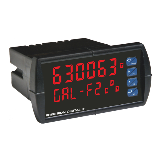
PD6300 Pulse Input Rate/Totalizer
•
Pulse, Open Collector, NPN, PNP, TTL, Switch Contact,
Sine Wave (Coil), Square Wave Inputs
•
Gate Function for Rate Display of Slow Pulse Rates
•
NEMA 4X, IP65 Front
•
Universal 85-265 VAC, or 12/24 VDC Input Power Models
•
Large Dual-Line 6-Digit Display, 0.60" & 0.46"
•
Isolated 24 VDC Transmitter Power Supply
•
Programmable Displays & Function Keys
•
Sunlight Readable Display Models
•
Rate Displayed as Units per Second, Minute, Hour, or Day
•
Total, Grand Total or Non-Resettable Grand Total
•
9-Digit Totalizer with Total Overflow Feature
•
K-Factor Calibration or Scale with up to 32-Point Linearization
•
2 or 4 Relays + Isolated 4-20 mA Output for Rate/Total/Grand Total
•
External 4-Relays & Digital I/O Expansion Modules
•
USB, RS-232 & RS-485 Serial Communication Options
•
®
Modbus
RTU Communication Protocol Standard
•
Configure, Monitor, and Datalog from a PC with
Free MeterView
PRECISION DIGITAL CORPORATION
233 South Street • Hopkinton MA 01748 USA
Tel (800) 343-1001 • Fax (508) 655-8990
Instruction Manual
®
Pro Software
www.predig.com
Advertisement
Table of Contents
Troubleshooting

Related Manuals for PRECISION DIGITAL pd6300


Summary of Contents for PRECISION DIGITAL pd6300
- Page 1 PD6300 Pulse Input Rate/Totalizer Instruction Manual • Pulse, Open Collector, NPN, PNP, TTL, Switch Contact, Sine Wave (Coil), Square Wave Inputs • Gate Function for Rate Display of Slow Pulse Rates • NEMA 4X, IP65 Front • Universal 85-265 VAC, or 12/24 VDC Input Power Models •...
-
Page 2: Limited Warranty
Anyone using this product for such applications does so at his/her own risk. Precision Digital Corporation shall not be held liable for damages resulting from such improper use. -
Page 3: Table Of Contents
Model PD6300 Pulse Input Rate/Totalizer Instruction Manual Table of Contents INTRODUCTION ------------------------------------------------------------ 6 ORDERING INFORMATION --------------------------------------------- 7 SPECIFICATIONS ---------------------------------------------------------- 8 General ------------------------------------------------------------------------------- 8 Rate Input ------------------------------------------------------------------------- 10 Rate/Totalizer -------------------------------------------------------------------- 11 Relays ------------------------------------------------------------------------------ 12 Isolated 4-20 mA Transmitter Output ------------------------------------ 13 ®... - Page 4 Model PD6300 Pulse Input Rate/Totalizer Instruction Manual Setting the Totalizer Features (total) ---------------------------------- 38 Setting the Input Units or Custom Tags (units) ---------------------- 39 Setting the Decimal Point (dEc pt) -------------------------------------- 40 Programming the Rate/Totalizer (prog) -------------------------------- 40 K-Factor Calibration (Factor) ----------------------------------------- 41 Multi-Point Calibration &...
- Page 5 Model PD6300 Pulse Input Rate/Totalizer Instruction Manual Control Menu (Contrl) -------------------------------------------------------- 66 Setting Up the Password (pass) ------------------------------------------- 66 Protecting or Locking the Meter ------------------------------------------- 67 Total Reset Password & Non-Resettable Total ----------------------- 67 Making Changes to a Password Protected Meter -------------------- 68...
-
Page 6: Introduction
4-20 mA output option. A digital input is standard. A fully loaded PD6300 pulse rate/totalizer meter has the following: four SPDT relays, 4-20 mA output, and two 24 VDC power supplies. The PD6300 capabilities may be enhanced by adding the following external expansion modules: four SPST relays (creating an eight-relay rate/totalizer), two digital I/O modules with four inputs and four outputs each, and RS-232, RS-485, and USB communication adapters. -
Page 7: Ordering Information
Model PD6300 Pulse Input Rate/Totalizer Instruction Manual ORDERING INFORMATION Standard Models 85-265 VAC 12/24 VDC Options Installed Model Model PD6300-6R0 PD6300-7R0 No options PD6300-6R2 PD6300-7R2 2 relays (PD1102*) PD6300-6R3 PD6300-7R3 4-20 mA output (PD1103*) PD6300-6R4 PD6300-7R4 4 relays (PD1104*) PD6300-6R5 PD6300-7R5 2 relays &... -
Page 8: Specifications
Model PD6300 Pulse Input Rate/Totalizer Instruction Manual SPECIFICATIONS Except where noted all specifications apply to operation at +25°C. General DISPLAY Upper display: 0.6" (15 mm) high, red LEDs Lower display: 0.46" (12 mm) high, red LEDs 6 digits: each (-99999 to 999999), with lead zero blanking. - Page 9 Model PD6300 Pulse Input Rate/Totalizer Instruction Manual ISOLATED Terminals P+ & P-: 24 VDC ± 10%. 12/24 VDC powered models TRANSMITTER selectable for 24, 10, or 5 VDC supply (internal jumper J4). POWER SUPPLY ProVu Series (PD6300): 85-265 VAC models rated @ 200 mA max, 12/24 VDC powered models rated @ 100 mA max, @ 50 mA max for 5 or 10 VDC supply.
-
Page 10: Rate Input
Model PD6300 Pulse Input Rate/Totalizer Instruction Manual Rate Input INPUTS Field selectable: Pulse or square wave 0-5 V, 0-12 V, or 0-24 V @ 30 kHz; TTL; open collector 4.7 kΩ pull-up to 5 V @ 30 kHz; NPN or PNP transistor, switch contact 4.7 kΩ... -
Page 11: Rate/Totalizer
Model PD6300 Pulse Input Rate/Totalizer Instruction Manual Rate/Totalizer DISPLAY The Upper and Lower displays may be assigned to rate, ASSIGNMENT total, grand total, alternate rate/total, alternate rate/grand total, set points, alternate rate/units, alternate total/units, alternate grand total/units, display Hi, display Lo, display Hi/Lo, display modbus, display units (lower display) and display Off (lower display). -
Page 12: Relays
Model PD6300 Pulse Input Rate/Totalizer Instruction Manual Relays RATING 2 or 4 SPDT (Form C) internal and/or 4 SPST (Form A) external; rated 3 A @ 30 VDC and 125/250 VAC resistive load; 1/14 HP (≈ 50 W) @ 125/250 VAC for inductive loads... -
Page 13: Isolated 4-20 Ma Transmitter Output
Model PD6300 Pulse Input Rate/Totalizer Instruction Manual Isolated 4-20 mA Transmitter Output OUTPUT Rate/process, total, grand total, max, min, set points 1-8, SOURCE Modbus input or manual control mode SCALING RANGE 1.000 to 23.000 mA for any display range. CALIBRATION Factory calibrated: 0.0 to 1000.0 = 4-20 mA output... -
Page 14: Modbus ® Rtu Serial Communications
Model PD6300 Pulse Input Rate/Totalizer Instruction Manual ® Modbus RTU Serial Communications SLAVE ID 1 – 247 (Meter address) BAUD RATE 300 - 19,200 bps TRANSMIT Programmable between 0 and 199 ms TIME DELAY DATA 8 bit (1 start bit, 1 or 2 stop bits) -
Page 15: Compliance Information
Model PD6300 Pulse Input Rate/Totalizer Instruction Manual COMPLIANCE INFORMATION Safety UL & c-UL LISTED USA & Canada UL 508 Industrial Control Equipment UL FILE NUMBER E160849 FRONT PANEL UL Type 4X, NEMA 4X, IP65; panel gasket provided LOW VOLTAGE EN 61010-1:2010... -
Page 16: Safety Information
Model PD6300 Pulse Input Rate/Totalizer Instruction Manual Note: Testing was conducted on PD6300 meters installed through the covers of grounded metal enclosures with cable shields grounded at the point of entry representing installations designed to optimize EMC performance. Declaration of Conformity available at www.predig.com... -
Page 17: Installation
Model PD6300 Pulse Input Rate/Totalizer Instruction Manual INSTALLATION There is no need to remove the meter from its case to complete the installation, wiring, and setup of the meter for most applications. Instructions are provided for setting up a 12/24 VDC powered meter to operate from 12 VDC and for changing the transmitter power supply to output 5 or 10 VDC instead of 24 VDC, see page 19. -
Page 18: Figure 2: Meter Dimensions - Side View
Model PD6300 Pulse Input Rate/Totalizer Instruction Manual Mounting Dimensions Figure 2: Meter Dimensions - Side View Figure 3: Meter Dimensions - Top View... -
Page 19: Configuration For 12 Or 24 Vdc Power Option
Model PD6300 Pulse Input Rate/Totalizer Instruction Manual Configuration for 12 or 24 VDC Power Option Do not exceed voltage rating of the selected configuration. Warning! Meters equipped with the 12/24 VDC power option are shipped from the factory ready to operate from 24 VDC. -
Page 20: Transmitter Supply Voltage Selection (P+, P-)
Model PD6300 Pulse Input Rate/Totalizer Instruction Manual Transmitter Supply Voltage Selection (P+, P-) All meters, including models equipped with the 12/24 VDC power option, are shipped from the factory configured to provide 24 VDC power for the transmitter or sensor. -
Page 21: Connectors Labeling
RJ45 M-LINK connector. Otherwise damage will Warning! occur to the equipment and the meter. Figure 6: Connector Labeling for Fully Loaded PD6300 Power Connections Power connections are made to a two-terminal connector labeled POWER on Figure 6. The meter will operate regardless of DC polarity connection. -
Page 22: Signal Connections
Model PD6300 Pulse Input Rate/Totalizer Instruction Manual Signal Connections Signal connections are made to a six-terminal connector labeled SIGNAL on Figure 6. The COM (common) terminal is the return for the input signals. The following figures show examples of signal connections. - Page 23 Model PD6300 Pulse Input Rate/Totalizer Instruction Manual Figure 11: NPN open Collector Input Figure 12: PNP Sensor Powered by Internal Supply Figure 13: Switch Input Connections...
-
Page 24: Modbus Rtu Serial Communications
Model PD6300 Pulse Input Rate/Totalizer Instruction Manual Modbus RTU Serial Communications Serial communications connection is made to an RJ45 connector labeled ® M-LINK on Figure 6. For interfacing to the P , use the PDA1232 for RS-232, the PDA1485 for RS-485, or the PDA8008 for USB. The same port is used for interfacing with all expansion modules (e.g. -
Page 25: Switching Inductive Loads
Figure 13: Low Voltage DC Loads Protection RC Networks Available from Precision Digital RC networks are available from Precision Digital and should be applied to each relay contact switching an inductive load. Part number: PDX6901. Note:... -
Page 26: F4 Digital Input Connections
Model PD6300 Pulse Input Rate/Totalizer Instruction Manual F4 Digital Input Connections A digital input, F4, is standard on the meter. This digital input connected with a normally open closure across F4 and COM, or with an active low signal applied to F4. -
Page 27: External Relay & Digital I/O Connections
Model PD6300 Pulse Input Rate/Totalizer Instruction Manual External Relay & Digital I/O Connections The relay and digital I/O expansion modules PDA1004 & PDA1044 are connected to the meter using the CAT5 cable provided with each module. The two RJ45 connectors on the expansion modules are identical and interchangeable;... -
Page 28: Interlock Relay Feature
Model PD6300 Pulse Input Rate/Totalizer Instruction Manual DI 1-4 DO 1-4 5 VDC Figure 18: Digital I/O Module Connections Interlock Relay Feature As the name implies, the interlock relay feature reassigns one, or more, alarm/control relays for use as interlock relay(s). Interlock contact(s) are wired to digital input(s) and trigger the interlock relay. -
Page 29: Setup And Programming
Model PD6300 Pulse Input Rate/Totalizer Instruction Manual SETUP AND PROGRAMMING • The meter has been factory calibrated to read input frequency in Hz (pulses/sec). The calibration equipment is certified to NIST standards. • Use the K-Factor menu to match the rate/totalizer with a flowmeter’s k-factor (pulse/unit of measure). -
Page 30: Front Panel Buttons And Status Led Indicators
Model PD6300 Pulse Input Rate/Totalizer Instruction Manual Front Panel Buttons and Status LED Indicators Button Description Status Symbol Menu Alarm 1 – 8 indicator Right arrow/F1 Rate indicator Up arrow/F2 Total indicator Enter/F3 Grand Total indicator Note: Total overflow ▲... -
Page 31: Display Functions And Messages
Model PD6300 Pulse Input Rate/Totalizer Instruction Manual Display Functions and Messages The meter displays various functions and messages during setup, programming, and operation. The following table shows the main menu functions and messages in the order they appear in the menu. - Page 32 Model PD6300 Pulse Input Rate/Totalizer Instruction Manual Display Parameter Action/Setting Description Total Program total conversion factor T CF conversion factor Total reset Program total reset mode: auto or manual T rst Grand total Program grand total time base GT tb...
- Page 33 Model PD6300 Pulse Input Rate/Totalizer Instruction Manual Display Parameter Action/Setting Description Automatic Set relay for automatic reset Auto Auto-manual Set relay for automatic & manual reset A-nman any time Latching Set relay for latching operation (relays LatcH assigned to rate)
- Page 34 Model PD6300 Pulse Input Rate/Totalizer Instruction Manual Display Parameter Action/Setting Description Output 1 Program output 1 value (e.g. 4.000 mA) Out 1 Display 2 Program display 2 value Dis 2 Out 2 Output 2 Program output 2 value (e.g. 20.000 mA)
-
Page 35: Main Menu
Model PD6300 Pulse Input Rate/Totalizer Instruction Manual Main Menu The main menu consists of the most commonly used functions: Reset, Control, Setup , and Password . • Press Menu button to enter Programming Mode then press the Up arrow button to scroll through the main menu. -
Page 36: Setting Numeric Values
Model PD6300 Pulse Input Rate/Totalizer Instruction Manual Setting Numeric Values The numeric values are set using the Right and Up arrow buttons. Press Right arrow to select next digit and Up arrow to increment digit value. The digit being changed is displayed brighter than the rest. -
Page 37: Setting Up The Rate/Totalizer Meter (Setup)
Model PD6300 Pulse Input Rate/Totalizer Instruction Manual Setting Up the Rate/Totalizer Meter (setup) The Setup menu is used to select: Enable or disable totalizer features Units for Rate, Total, and Grand Total Decimal point position Input Calibration Display parameter and intensity... -
Page 38: Setting The Input Signal (Input)
Model PD6300 Pulse Input Rate/Totalizer Instruction Manual Setting the Input Signal (Input) There is a switch, located to the right of the input connector, which must be configured according to the input level and type. Jumper J4 located inside the meter, behind the input signal connector, is used to select the excitation voltage (24 V*, 10 V or 5 V) which is supplied to the P+ and P- wiring terminals. -
Page 39: Setting The Input Units Or Custom Tags (Units)
Model PD6300 Pulse Input Rate/Totalizer Instruction Manual Setting the Input Units or Custom Tags (units) Enter the input unit or custom tag that will be displayed if alternating rate, total, or grand total and units is selected in the units menu, or d unit is selected as the lower display parameter. -
Page 40: Setting The Decimal Point (Dec Pt)
Model PD6300 Pulse Input Rate/Totalizer Instruction Manual Setting the Decimal Point (dEc pt) The decimal point may be set with up to five decimal places or with no decimal point at all. The rate, total, and grand total decimal points are independent. -
Page 41: K-Factor Calibration (Factor)
Model PD6300 Pulse Input Rate/Totalizer Instruction Manual Additional parameters, not needed for most applications, are programmed in the Advanced Features menu; see Advanced Features Menu , page 69. K-Factor Calibration (Factor) The meter may be calibrated using the K-Factor function. Most flowmeter manufacturers provide this information with the device. -
Page 42: Scaling The Meter (Scale)
Model PD6300 Pulse Input Rate/Totalizer Instruction Manual Scaling the Meter (SCALE) The pulse inputs can be scaled to display the process variable in engineering units. A signal source is not needed to scale the meter; simply program the inputs and corresponding display values. -
Page 43: Gate Function (Gate)
Model PD6300 Pulse Input Rate/Totalizer Instruction Manual Error Message (Error) An error message indicates that the calibration or scaling process was not successful. After the error message is displayed, the meter reverts to input 2 during calibration or scaling, allowing the appropriate input signal to be applied or programmed. -
Page 44: Contact De-Bounce Filter (Filter)
Model PD6300 Pulse Input Rate/Totalizer Instruction Manual Gate Settings Slow Pulse Rate Low Gate* (sec) High Gate (sec) Min Freq** (Hz) 0.5000 10.0 0.1000 20.0 0.0500 100.0 0.0100 200.0 0.0050 400.0 0.0025 800.0 0.0012 999.9 0.0010 *The low gate setting corresponds to the display update rate and is used to stabilize the display reading with a fluctuating signal. -
Page 45: Time Base, Total Conversion Factor & Total Reset
Model PD6300 Pulse Input Rate/Totalizer Instruction Manual Time Base, Total Conversion Factor & Total Reset The time base, total conversion factor, and total reset menus are located in the Program menu. The total and grand total have their own independent settings. This... -
Page 46: Calibrating The Meter With External Source (Cal)
Model PD6300 Pulse Input Rate/Totalizer Instruction Manual Calibrating the Meter with External Source (Cal) To scale the meter without a signal source refer to K-Factor Calibration (Factor) on page 41 or Scaling the Meter (SCALE) on page 42 The meter can be calibrated to display the process variable in engineering units by applying the appropriate input signal and following the calibration procedure. -
Page 47: Setting The Display Parameter & Intensity (Dsplay)
Model PD6300 Pulse Input Rate/Totalizer Instruction Manual Setting the Display Parameter & Intensity (dsplay) The upper display ( Big ) can be programmed to display: Rate value Total or grand total Relay set points Max & min values Modbus input... -
Page 48: Display Setup Menu
Model PD6300 Pulse Input Rate/Totalizer Instruction Manual Display Setup Menu After setting up the input and the display, press the Menu button to exit programming and skip the rest of the setup menu. Press the Menu button again and the Up arrow to reach the Program menu and complete... -
Page 49: Setting The Relay Operation (Relay)
Model PD6300 Pulse Input Rate/Totalizer Instruction Manual Setting the Relay Operation (relay) This menu is used to set up the operation of the relays. During setup, the relays do not follow the input and they will remain in the state found prior to entering the Relay menu. -
Page 50: Relay Assignment (Assign)
Model PD6300 Pulse Input Rate/Totalizer Instruction Manual Relay Assignment (Assign) The relays can be assigned to any of the following parameters: Rate for low or high alarm indication Total for alarm indication Grand total for alarm indication Modbus input... -
Page 51: Setting The Relay Action
Model PD6300 Pulse Input Rate/Totalizer Instruction Manual Setting the Relay Action Operation of the relays is programmed in the Action menu. The relays may be set up for any of the following modes of operation: Automatic reset (non-latching) Automatic + manual reset at any time (non-latching) -
Page 52: Programming Set And Reset Points
Model PD6300 Pulse Input Rate/Totalizer Instruction Manual Programming Set and Reset Points High alarm indication: program set point above reset point. Low alarm indication: program set point below reset point. The deadband is determined by the difference between set and reset points. -
Page 53: Relay And Alarm Operation Diagrams
Model PD6300 Pulse Input Rate/Totalizer Instruction Manual Relay and Alarm Operation Diagrams The following graphs illustrate the operation of the relays, status LEDs, and ACK button. High Alarm Operation (Set > Reset) For Manual reset mode, ACK can be pressed anytime to turn "off" relay. -
Page 54: Low Alarm Operation (Set < Reset)
Model PD6300 Pulse Input Rate/Totalizer Instruction Manual Low Alarm Operation (Set < Reset) For Manual reset mode, ACK can be pressed anytime to turn "off" relay. For relay to turn back “on”, signal must go above set point and then go... -
Page 55: High Alarm With Fail-Safe Operation (Set > Reset)
Model PD6300 Pulse Input Rate/Totalizer Instruction Manual High Alarm with Fail-Safe Operation (Set > Reset) Note: Relay coil is energized in non-alarm condition. In case of power failure, relay will go to alarm state. -
Page 56: Low Alarm With Fail-Safe Operation (Set < Reset)
Model PD6300 Pulse Input Rate/Totalizer Instruction Manual Low Alarm with Fail-Safe Operation (Set < Reset) Note: Relay coil is energized in non-alarm condition. In case of power failure, relay will go to alarm state. -
Page 57: Alternation Control Operation
Model PD6300 Pulse Input Rate/Totalizer Instruction Manual... -
Page 58: Rate Relay Sampling Operation
Model PD6300 Pulse Input Rate/Totalizer Instruction Manual Rate Relay Sampling Operation Input Reset Sample Sample Sample Time Time Time Relay When the signal crosses the set point, the relay trips and the sample time starts. After the sample time has elapsed, the relay resets. The cycle repeats every time the set point is crossed, going up for high alarms and going down for low alarms. -
Page 59: Time Delay Operation
Model PD6300 Pulse Input Rate/Totalizer Instruction Manual Time Delay Operation The following graphs show the operation of the time delay function. When the signal crosses the set point, the On time delay timer starts and the relay trips when the time delay has elapsed. If the signal drops below the set point (high alarm) before the time delay has elapsed, the On time delay timer resets and the relay does not change state. -
Page 60: Relay Operation Details
Model PD6300 Pulse Input Rate/Totalizer Instruction Manual Relay Operation Details Overview The relay capabilities of the meter expand its usefulness beyond simple indication to provide users with alarm and control functions. These capabilities include front panel alarm status LEDs as well as either 2 or 4 optional internal relays and/or 4 external relays expansion module. -
Page 61: Front Panel Leds
Model PD6300 Pulse Input Rate/Totalizer Instruction Manual Front Panel LEDs The LEDs on the front panel provide status indication for the following: Status Status Alarm 1 Alarm 5 Alarm 2 Alarm 6 Alarm 3 Alarm 7 Alarm 4 Alarm 8 The meter is supplied with four alarm points that include front panel LEDs to indicate alarm conditions. -
Page 62: Non-Latching Relay (Auto)
Model PD6300 Pulse Input Rate/Totalizer Instruction Manual Non-Latching Relay (Auto) Automatic reset only Condition Relay Normal Alarm Ack (No effect) Normal In this application, the meter is set up for automatic reset (non-latching relay). Acknowledging the alarm while it is still present has no effect on either the LED or the relay. -
Page 63: Latching Relay (Lt-Clr)
Model PD6300 Pulse Input Rate/Totalizer Instruction Manual Latching Relay (Lt-Clr) Manual reset only after alarm condition has cleared Condition Relay Normal Alarm Ack (No effect) Normal In this application, the meter is set up for manual reset only after the signal passes the reset point (alarm condition has cleared). -
Page 64: Setting Up The Interlock Relay (Force On) Feature
Model PD6300 Pulse Input Rate/Totalizer Instruction Manual Setting Up the Interlock Relay (Force On) Feature Relays 1-4 can be set up as interlock relays. To set up the relays for the interlock feature: 1. Access the Setup – Relay – Action menu and set the action to off. -
Page 65: Scaling The 4-20 Ma Analog Output (Aout)
Model PD6300 Pulse Input Rate/Totalizer Instruction Manual Interlock Relay Operation Example Relays 1 & 2 are configured to energize (their front panel LEDs are off) when SW1 & SW2 switches (above) are closed. If the contacts to these digital inputs are opened, the corresponding front panel LEDs flash indicating this condition. -
Page 66: Reset Menu (Reset)
Model PD6300 Pulse Input Rate/Totalizer Instruction Manual Reset Menu (reset) The Reset menu is used to reset the totals, maximum or minimum reading (peak or valley) reached by the process; both may be reset at the same time by selecting “reset high & low” ( rst HL ). -
Page 67: Protecting Or Locking The Meter
Model PD6300 Pulse Input Rate/Totalizer Instruction Manual Protecting or Locking the Meter Enter the Password menu and program a six-digit password. For instructions on how to program numeric values see Setting Numeric Values , page 36. Record the password for future reference. If appropriate, it may be recorded in the space provided. -
Page 68: Making Changes To A Password Protected Meter
Model PD6300 Pulse Input Rate/Totalizer Instruction Manual Making Changes to a Password Protected Meter If the meter is password protected, the meter will display the message Locd ( Locked ) when the Menu button is pressed. Press the Enter button while the message is being displayed and enter the correct password to gain access the menu. -
Page 69: Advanced Features Menu
Model PD6300 Pulse Input Rate/Totalizer Instruction Manual Advanced Features Menu To simplify the setup process, functions not needed for most applications are located in the Advanced Features menu. Press and hold the Menu button for three seconds to access the advanced features of the meter. - Page 70 Model PD6300 Pulse Input Rate/Totalizer Instruction Manual Display Parameter Action/Setting Transmit delay Set transmit delay for serial Tr dLY communication Parity Select parity: Parity Even, Odd, or None with 1 or 2 stop bits Time byte Set byte-to-byte timeout t-byt...
- Page 71 Model PD6300 Pulse Input Rate/Totalizer Instruction Manual Display Parameter Action/Setting Digital input 1 Assign digital input 1 – 8, if expansion dI I modules are connected Digital output 1 Assign digital output 1 – 8, if expansion dO 1 modules are connected...
-
Page 72: Rounding Feature (Round)
0 and 199 ms. The parity can be set to even, odd, or none with 1 or 2 stop bits. The PD6300 can also be connected to another PD6300 with a special PDA1200 cable, allowing the user to copy all the settings from one meter... -
Page 73: Select Menu (Select)
Model PD6300 Pulse Input Rate/Totalizer Instruction Manual Select Menu (SElEct) The Select menu is used to select the signal input conditioner applied to the input (linear), low-flow cutoff, and analog output programming. The multi-point linearization is part of the linear function selection. -
Page 74: Multi-Point Linearization (Linear)
Model PD6300 Pulse Input Rate/Totalizer Instruction Manual Multi-Point Linearization (Linear) Meters are set up at the factory for linear function with 2-point linearization. Up to 32 linearization points can be selected under the linear function. The multi-point linearization can be used to linearize the display for non-linear signals. -
Page 75: Analog Output Programming (Aoutpr)
Model PD6300 Pulse Input Rate/Totalizer Instruction Manual Analog Output Programming (AoutPr) The Analog Output Programming menu is used to program the behavior of the 4-20 mA output. The following parameters and functions are programmed in this menu: Source: Source for generating the 4-20 mA output (e.g. PV) -
Page 76: Programmable Function Keys User Menu (User)
Model PD6300 Pulse Input Rate/Totalizer Instruction Manual Programmable Function Keys User Menu (user) The User menu allows the user to assign the front panel function keys F1, F2, F3, F4 (digital input) and up to eight digital inputs to access most of the menus or to activate functions immediately (e.g. -
Page 77: Meter Copy Function (Copy)
Model PD6300 Pulse Input Rate/Totalizer Instruction Manual Meter Copy Function (Copy) The Copy function is used to copy (or clone) all the settings from one meter to other meters requiring exactly the same setup and programming (i.e. type of input, scaling, decimal point, filter, gate, etc.). - Page 78 Model PD6300 Pulse Input Rate/Totalizer Instruction Manual Meter Copy or Cloning Instructions Do not connect the two meters to the same signal source while cloning. Internal calibration may Caution! be affected. Connect two meters using a PDA1200 meter copy cable.
-
Page 79: Meter Operation
Model PD6300 Pulse Input Rate/Totalizer Instruction Manual METER OPERATION The meter accepts pulses (e.g. ±40mV to ± 8V), square wave (0-5, 0- 12V, or 0-24V), open collector NPN, PNP, TTL, or switch contact signals and displays these signals in engineering units from -99999 to 999999. -
Page 80: F4 Operation
Model PD6300 Pulse Input Rate/Totalizer Instruction Manual F4 Operation A digital input, F4, is standard on the meter. This digital input is programmed identically to function keys F1, F2, and F3. The input is triggered with a contact closure to COM, or with an active low signal. -
Page 81: Troubleshooting
Model PD6300 Pulse Input Rate/Totalizer Instruction Manual TROUBLESHOOTING The rugged design and the user-friendly interface of the meter should make it unusual for the installer or operator to refer to this section of the manual. However, due to the many features and functions of the meter, it’s possible that the setup of the meter does not agree with what an... -
Page 82: Reset Meter To Factory Defaults
Model PD6300 Pulse Input Rate/Totalizer Instruction Manual Reset Meter to Factory Defaults When the parameters have been changed in a way that is difficult to determine what’s happening, it might be better to start the setup process from the factory defaults. -
Page 83: Factory Defaults & User Settings
Model PD6300 Pulse Input Rate/Totalizer Instruction Manual Factory Defaults & User Settings The following table shows the factory setting for most of the programmable parameters on the meter. Next to the factory setting, the user may record the new setting for the particular application. - Page 84 Model PD6300 Pulse Input Rate/Totalizer Instruction Manual Parameter Display Default Setting User Setting Relay 1 assignment Total Asign1 Relay 2 assignment Total Asign2 Relay 3 assignment Rate Asign3 Relay 4 assignment Rate Asign4 Relay 1 action Automatic Act 1 Relay 1 set point 100.0...
- Page 85 Model PD6300 Pulse Input Rate/Totalizer Instruction Manual Parameter Display Default Setting User Setting Display 2 analog out 1000.0 Dis 2 Output 2 value 20.000 mA Out 2 Source analog output Rate/process Source Overrange output O-rang 21.000 mA Underrange output 3.000 mA...
-
Page 86: Troubleshooting Tips
Model PD6300 Pulse Input Rate/Totalizer Instruction Manual Troubleshooting Tips Symptom Check/Action Check power at power connector No display at all Meter is password-protected, enter Not able to change setup or correct six-digit password to unlock programming, Locd is displayed Check:... - Page 87 Model PD6300 Pulse Input Rate/Totalizer Instruction Manual This Page Intentionally Left Blank...
-
Page 88: Figure 22: 1/8 Din Panel Cutout Template
Model PD6300 Pulse Input Rate/Totalizer Instruction Manual Figure 22: 1/8 DIN Panel Cutout Template... -
Page 89: Eu Declaration Of Conformity
233 South Street Hopkinton, MA 01748 USA as the manufacturer, declare under our sole responsibility that the product(s), Model PD6300 ProVu Series Pulse Input Rate/Totalizer Meter to which this declaration relates, is in conformity with the European Union Directives shown below:... - Page 90 Model PD6300 Pulse Input Rate/Totalizer Instruction Manual How to Contact Precision Digital • For Technical Support please Call: (800) 610-5239 or (508) 655-7300 Fax: (508) 655-8990 Email: support@predig.com • For Sales Support or to place an order please Call: (800) 343-1001 or (508) 655-7300 Fax: (508) 655-8990 Email: sales@predig.com...
Need help?
Do you have a question about the pd6300 and is the answer not in the manual?
Questions and answers