Table of Contents
Advertisement
Advertisement
Table of Contents

Related Manuals for Henkelman Jumbo series


Summary of Contents for Henkelman Jumbo series
- Page 1 USER MANUAL Vacuum Packing Machine Jumbo series Art nr 0894606...
- Page 2 No part of this publication may be reproduced, stored in a retrieval system, or transmitted in any form or by any electronic or mechanical means, or by photocopying, recording, or otherwise without the prior written consent of Henkelman BV. USER MANUAL...
- Page 3 INTRODUCTION Henkelman BV is a supplier of ultra-modern vacuum packing machines. Our machines are designed and manufactured to the highest standards. And that's clear. They combine a sleek built and functional design with ease of use and durability. Installation is just a matter of 'plug &...
-
Page 4: Table Of Contents
TABLE OF CONTENTS LIST OF FIGURES ..........................5 EC DECLARATION OF CONFORMITY (COPY) ................... 6 LIST OF SYMBOLS ..........................7 ICONS ..............................8 TECHNICAL INFORMATION ......................9 DESCRIPTION OF THE MACHINE ....................10 2.1............11 ESCRIPTION OF THE PACKAGING PROCESS MACHINE FUNCTIONS 2.1.1. -
Page 5: List Of Figures
LIST OF FIGURES 1: O ..................10 IGURE VERVIEW OF THE MAIN COMPONENTS 2: O ....................12 IGURE VERVIEW OF THE SEAL SYSTEM 3: O ) ..............15 IGURE VERVIEW OF THE PUMP FILTER COVER REMOVED 4: O ................16 IGURE VERVIEW OF THE ELECTRICAL INSTALLATION 5: C... -
Page 6: Ec Declaration Of Conformity (Copy)
Henkelman BV Titaniumlaan 10 5221 CK, ‘s Hertogenbosch Nederland declare under our sole responsibility that the product; Machine type: Jumbo Series fulfils all the relevant provisions of the directives 2006/42/EG Machinery Directive 2004/108/EG EMC-Directive and is in conformity with the following standard(s) or other normative document(s);... -
Page 7: List Of Symbols
LIST OF SYMBOLS For all operations in which the safety of the operator and/or technician is at stake and where caution should be exercised, the following symbols are used. Caution! Danger: High Voltage! Tip: Provides a quick overview or offers tips to make it easier to perform certain actions USER MANUAL Jumbo Version: JUM-EN-UL-0... -
Page 8: Icons
ICONS Some icons and warnings are included on the machine among others to indicate the possible risks involved to the users. ICON DESCRIPTION LOCATION Nameplate At the rear of the machine Warning sign "HIGH VOLTAGE" At the rear of the machine Warning sign “SHOCK RISK”... -
Page 9: Technical Information
1. TECHNICAL INFORMATION Jumbo General ˚F Ambient temperature 41 - 86 41 - 86 41 - 86 41 - 86 41 - 86 41 - 86 41 - 86 Noise production < 70 < 70 < 70 < 70 < 70 <... -
Page 10: Description Of The Machine
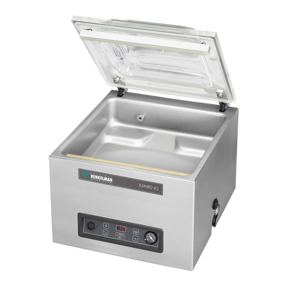
2. DESCRIPTION OF THE MACHINE FUNCTION This chapter provides an overview of the main components and functions If detailed information is available in this guide, you will be redirected to the specific sections The performance of your machine may differ from the figure below The figure below shows the main components of the system: Figure 1: Overview of the main components PART... -
Page 11: Description Of The Packaging Process / Machine Functions
PART DESCRIPTION SECTION Controlpanel See section Machine housing The machine frame contains all necessary parts for the correct functioning of the machine Vacuum pump See section Power connection See section 2.1. Description of the packaging process / machine functions FUNTION ... -
Page 12: General Functions
STEP PROCESS PHASE OPERATION Open vacuum chamber The lid opens Remove the product The operator can remove the packed product from the worktable 2.1.2. General Functions FUNCTION ICON OPERATION Cleaning the pump The pump cleaning program allows for a proper flushing of the pump. - Page 13 PART DESCRIPTION SECTION Seal bar The seal bar consists of the following components Seal wires: the sealing wires are heated for a certain period of time so that the open side of the vacuum bag will melt together during the sealing ...
-
Page 14: De Vacuum Pump
2.3. De vacuum pump FUNCTION The vacuum pump creates a vacuum in the chamber 3 en 4 m USER MANUAL Jumbo Version: JUM-EN-UL-0 23-03-15... -
Page 15: Figure 3: Overview Of The Pump (Filter Cover Removed)
16 m Figure 3: Overview of the pump (filter cover removed) PART DESCRIPTION SECTION Vacuum pump Creates the vacuum during the process Exhaust filter Filters the exhaust air and absorbs oil vapors Refer to the indicated section for detailed information with regards to maintenance ... -
Page 16: Electrical Installation
2.4. Electrical installation FUNCTION The electrical installation provides power to the vacuum pump, sealing system and control unit See the electrical diagram for the further structure and operation of the electrical installation. For the electrical diagram, please contact your dealer ATTENTION! ... -
Page 17: Single Program Digital Control (Spdc)
2.5. Single Program Digital Control (SPDC) FUNCTION The machine can be operated The program can be modified See chapter 0 for instructions on operation and programming Figure 5: Control panel Single Program Digital Control(SPDC) ELEMENT EXPLANATION On / Off button This button turns the machine on/off ... - Page 18 ELEMENT EXPLANATION “+/stop vacuum” key Stops the current function and continues with the next program step In the programming mode this key decreases the value of the selected parameter Vacuum gauge Shows the pressure in the vacuum chamber ...
-
Page 19: Safety
3. SAFETY 3.1. General ATTENTION! Never pack products that can be damaged by vacuum Never pack living animals Warranty and/or liability expires if any damage is caused by repairs and/or modifications that are not authorized by the supplier or any of its distributors ... -
Page 20: During Normal Operation
3.2. During normal operation ATTENTION! Before starting, ensure that no work is done on the system and that it is ready to use the machine Unauthorized persons must not operate the machine. Checking this is the task of the machine operator(s) ... -
Page 21: Installation
4. INSTALLATION EXPLANATION Refer to chapter 1: Technical information for the correct specifications 4.1. Transport and placement ATTENTION! The machine must be moved and transported upwards Place the machine on a flat, level surface. This is essential for trouble-free operation of the machine ... -
Page 22: Operation
5. OPERATION ATTENTION Observe the instructions in chapter 3 for all work to be performed Failure to follow or ignore this may result in serious injury EXPLANATION It is possible to optimize a program for your products by changing the parameters of the program, see Chapter 5.5 5.1. -
Page 23: Continue To The Next Step Of The Cycle
5.3. Continue to the next step of the cycle EXPLANATION For some products, it may be necessary to proceed to the next step of the packing cycle, before the vacuum time or the vacuum level is reached WHAT TO DO ACTION RESULT ... -
Page 24: Changing The Program Settings
5.5. Changing the program settings 5.5.1. Single Program Digital Control (SPDC) EXPLANATION This section describes how parameters can be modified and indicates the units and limits of the parameters Figure 6: Changing parameters (SPDC) WHAT TO DO ACTION RESULT Select the parameter Press the cursor key (Figure 6:1) to scroll thourgh the parameters... -
Page 25: External Vacuum Option (Spdc)
5.5.1.1. External vacuum option (SPDC) EXPLANATION With this function vacuum can be applied to special food packaging gastronorm containers outside the machine First check whether the container is resistant to a vacuum and can retain this Figure 7: External vacuum adapter kit (SPDC) WHAT TO DO ACTION RESULT... -
Page 26: Directive For Function Values
5.6. Directive for function values EXPLANATION For each function, values can be set if you are authorized as the owner. In order to understand the impact of the set value the table below explains the consequences of giving a low or high value for each function FUNCTION RANGE CONDITIONS... -
Page 27: Figure 8: Water Vapour Line
Figure 8: Water vapour line USER MANUAL Jumbo Version: JUM-EN-UL-0 23-03-15... -
Page 28: Maintenance
6. MAINTENANCE ATTENTION! Always disconnect the power supply by unplugging the power cord Test the machine after maintenance or repairs, so it is certain that the machine can be safely used Only trained personnel should perform the described maintenance work 6.1. -
Page 29: Cleaning The Machine
ACTIVITY LUBRICANT SECTION Replacements Replace the sealing wires Replace the silicone rubber of the silicone holders Replace the lid seal Replace the exhaust filter Please contact your supplier for a professional service Replace the plastic lid 6.2. Cleaning the machine EXPLANATION ... -
Page 30: Oil Cleaning Program
6.3. Oil cleaning program EXPLANATION The oil cleaning program will let the vacuum pump run for 15 minutes. During the program, the pump and the oil will reach the operating temperature. The oil absorbs fluid in the pump. The high temperature ensures that the moisture evaporates in the pump and reduces the risk of corrosion ... - Page 31 Add oil WHAT TO DO ACTION RESULT Add oil Remove the oil filler plug (Figure 3:5) Add oil until the oil level is between the "max" and "min" level (Figure 3:3) Place back the oil filler plug Replacing oil WHAT TO DO ACTION...
-
Page 32: Replacing The Exhaust Filter (Maintenance Of Vacuum Pump)
6.5. Replacing the exhaust filter (maintenance of vacuum pump) EXPLANATION 1. The exhaust filter prevents oil vapors to be emitted by the exhaust air from the vacuum pump 2. If the filter becomes saturated, it is no longer possible to reach maximum vacuum 3. -
Page 33: Figure 10: Replacing The Exhaust Filter On A 8 M 3 Pomp
pump Figure 10: Replacing the exhaust filter on a 8m pomp WHAT TO DO ACTION RESULT Remove the exhaust Remove the filter cover (Figure 10:3) from filter the vacuum pump (Figure 10:1) Screw the old filter (Figure 10:2) out of the vacuum pump ... -
Page 34: Figure 11: Replacing The Exhaust Filter On A 16 M 3 Pomp
16 m pump Figure 11: Replacing the exhaust filter on a 16m pomp WHAT TO DO ACTION RESULT Remove the exhaust Remove the filter cover (Figure 11:4) van filter from the vacuum pump (Figure 11:1) Remove the leaf spring (Figure 11:3) ... -
Page 35: Replacing The Sealing Wire
6.6. Replacing the sealing wire EXPLANATION Depending on your machine specification you can have one of the following (combinations of) seal elements: • Double seal: Two sealing wires • Cut-off seal: One sealing wire and one cutting wire • Wide sealing: One wide sealing wire ... - Page 36 WHAT TO DO ACTION RESULT Remove the seal bar Lift the sealing bar (Figure 12:1) from the from his holders cylinders Remove the teflon Remove the teflon tape (Figure 13:1) that tape protects the sealing wires Remove the old Remove the screws (Figure 13:2) on the sealing wires bottom side of the seal bar, and remove...
-
Page 37: Replacing The Silicone Rubber On The Silicone Holders
6.7. Replacing the silicone rubber on the silicone holders EXPLANATION In order to obtain a seal of good quality, the rubber should not be damaged and the surface must be flat Damage may be caused by burning with the seal wire or mechanical contact ... -
Page 38: Replacing The Lid Gasket
6.8. Replacing the lid gasket EXPLANATION The lid gasket ensures that the vacuum chamber is completely closed off during the machine cycle. This is essential for the achievement of a maximum vacuum level. The lid gasket will wear out due to extreme pressure differences and should be changed regularly ... -
Page 39: Troubleshooting
7. TROUBLESHOOTING The tables below show the possible interference with the corresponding cause and action to be taken MALFUNCTION ACTIVITY SECTION Control panel does not illuminate Connect the machine to the power supply The control panel is on but there is no Please contact Check / adjust the micro switch of the lid activity after closing the lid... -
Page 40: Warranty Conditions
The warranty is subject to the following limitations. The warranty period for products supplied by Henkelman is 3 years from the date of the purchase document. This warranty is limited to manufacturing and machine errors, and therefore does not cover malfunctions due to a component of the product that has been exposed to any type of wear. -
Page 41: Dispose As Waste
9. DISPOSE AS WASTE Do not dispose oil and components with the household waste. Ensure that at the replacement of parts or oil after the lifecycle, that all materials are collected and destroyed or recycled in a legal and environmentally friendly manner. USER MANUAL Jumbo Version: JUM-EN-UL-0... -
Page 42: Appendix
10. APPENDIX 10.1. Log This log should include among other things: ● Annual maintenance ● Big replacements and emergencies ● Modifications ● Tests of the emergency stop buttons and safety devices DATE: EXECUTED BY: DESCRIPTION: (AUTORITY, (NATURE OF THE ACTIVITIES, WHAT IS REPLACED) TECHNICIAN) USER MANUAL Jumbo... - Page 43 USER MANUAL Jumbo Version: JUM-EN-UL-0 23-03-15...
- Page 44 USER MANUAL Jumbo Version: JUM-EN-UL-0 23-03-15...
Need help?
Do you have a question about the Jumbo series and is the answer not in the manual?
Questions and answers