
Related Manuals for Axxess AXi-MBEIRC-R


Summary of Contents for Axxess AXi-MBEIRC-R
- Page 1 AXi-MBEIRC-R INSTALLATION MANUAL PLEASE REVIEW THIS INSTALLATION MANUAL CAREFULLY BEFORE BEGINNING ANY WORK PLUG & PLAY WIRING HARNESS COMPATIBLE WITH AXi-RGB2 AXi-RGB3...
-
Page 2: Table Of Contents
Table Of Contents ………………………………….………. COMPATIBLE VEHICLES/WIRING LOCATIONS…..3 PRECAUTIONS.……………………………………..……...4 WIRING CONNECTIONS……………………….…...…..5 PLUG & PLAY HARNESS INSTALLATION……..6-10 TESTING OPERATION………………………….……...….11 VEHICLE REASSEMBLY CHECKLIST…………...…..12 IMPORTANT WARNING This product includes instructions for installation which must be carefully followed. The instructions are worded in such a manner to assume that the installer is capable of completing these type of electronic installations. -
Page 3: Compatible Vehicles/Wiring Locations
…….…… WORKS ON VEHICLES WITH OR WITHOUT NAVIGATION COMPATIBLE VEHICLES MAKE MODEL YEAR MAYBACH 2003-2012 MAYBACH 2003-2012 MERCEDES-BENZ CLS-CLASS 2006-2008 MERCEDES-BENZ E-CLASS 2003-2008 MERCEDES-BENZ SLK-CLASS 2005-2008 ACCESSORY GROUND REVERSE LOCATION MAKE MODEL YEAR ACCESSORY GROUND REVERSE MAYBACH 2003-2012 FUSE BOX RADIO GND REV. -
Page 4: Precautions
Using protective blankets to cover front seats, interior of the vehicle and center console. Always install a fuse 6-12 inches away from AXXESS.i interface, 5 amp fuse should be used. Always secure AXXESS.i interface with Velcro or double side tape to prevent rattling of the interface. -
Page 5: Wiring Connections
Simply tap in to the factory video signal with the RCA wire and connect that RCA wire to video 1 input of an AXXESS.i AXi-RGB2/AXi-RGB3 video interface. -
Page 6: Plug & Play Harness Installation
Step 1: Access the flex cable connectors, see page 7 step 1-2. Step 2: Disconnect the factory flex cable, see page 8 step 3. Step 3: Connect supplied flex cable of AXi-MBEIRC-R, see page 8 step 4 Step 4: Reroute factory flex cable to AXi-MBEIRC-R, see page 9 step 4. - Page 7 AXi-MBEIRC-R Installation STEP 1: TOP COVER REMOVAL. Remove two large screws from the top of radio. When done, open the cover by pulling it up. DO NOT detach cover until the next step is completed. Pic 1 STEP 2: DISCONNECTING ORIGINAL RIBBON CABLE.
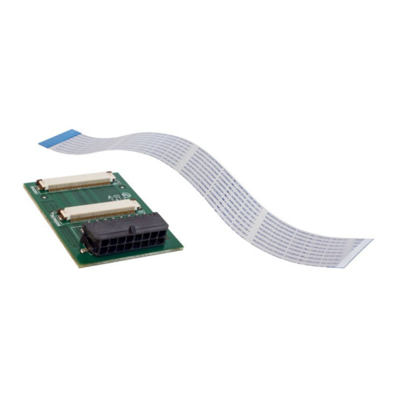
- Page 8 Pic 3 STEP 4: INSTALLING AXi-MBEIRC-R BOARD. Connect provided ribbon cable to bottom connector of AXi-MBEIRC-R board. Insert flex ribbon cable from AXi-MBEIRC-R board into the radio. Pic 4 STEP 4 CONTINUED ON THE NEXT PAGE.
- Page 9 STEP 5: MAKING AN OPENING IN THE RADIO COVER. Note the spot show on the picture. In order to connect AXi-MBEIRC-R cable you will need to cut an opening in the cover of the radio in a location shown.
- Page 10 Pic 7 STEP 7: RECONNECTING CABLES AND CLOSING RADIO. Connect AXi-MBEIRC-R harness to AXi-MBEIRC board as shown. Reconnect the ribbon cable from the CD changer to the radio and close the cover. Replace two screws from top of the radio.
-
Page 11: Testing Operation
OFF, please see installation manual of the AXi-RGB2/AXi-RGB3) interface you are installing for details. After The Installation • Test all functions of AXXESS.i Interface. • Check operation of all dashboard components such Heat and AC controls, hazard lights, headunit operation etc. -
Page 12: Vehicle Reassembly Checklist
Vehicle Reassembly Checklist When performing vehicle reassembly, please make sure to go over the list and checkoff check mark boxes : Check to see if all connectors behind the screen, radio, HVAC etc. were reconnected. Check that LCD screen shuts off with key off, and turns back on with key on. Check touch‐screen operation.
Need help?
Do you have a question about the AXi-MBEIRC-R and is the answer not in the manual?
Questions and answers