Advertisement
Available languages
Available languages
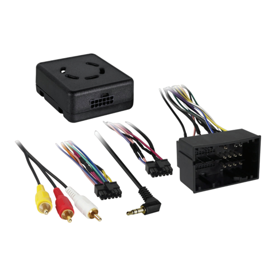
INTERFACE COMPONENTS
• AXRC-CH1 interface
• AXRC-CH1 harness
APPLICATIONS
RAM
1500/2500/3500
(small screen option)
2013-2017
AxxessInterfaces.com
Ram Data Interface
INTERFACE FEATURES
• Provides accessory power (12-volt 10-amp)
• Retains R.A.P. (retained accessory power)
• Used in non-amplified models, or when bypassing a factory amplifier
• Provides NAV outputs (parking brake, reverse, and speed sense)
• Pre-wired AXSWC harness (AXSWC sold separately)
• Retains the factory backup camera (if displayed through the OE radio)
• Retains the 3.5mm AUX-IN jack
• Retains balance and fade
• Retains safety chimes
• Micro-B USB updatable
Chassis Cab 3500/4500/5500
(small screen option)
2013-2017
© COPYRIGHT 2019 METRA ELECTRONICS CORPORATION
2013-2017
AXRC-CH1
I N S TA L L AT I O N I N S T R U C T I O N S
TABLE OF CONTENTS
Connections ............................................................2
Installation .............................................................3
Programming .........................................................3
TOOLS REQUIRED
• Wire cutter • Crimp tool • Solder gun • Tape
• Connectors (example: butt-connectors, bell
caps, etc.)
Product Info
REV. 9/30/19 INSTAXRC-CH1
Advertisement
Table of Contents

Related Manuals for Axxess AXRC-CH1


Summary of Contents for Axxess AXRC-CH1
- Page 1 • Connectors (example: butt-connectors, bell • Retains the 3.5mm AUX-IN jack caps, etc.) • Retains balance and fade • Retains safety chimes • Micro-B USB updatable INTERFACE COMPONENTS • AXRC-CH1 interface • AXRC-CH1 harness Product Info APPLICATIONS 1500/2500/3500 Chassis Cab 3500/4500/5500 (small screen option)
- Page 2 CONNECTIONS The following (3) wires are only for multimedia/navigation radios that require these wires. From the AXRC-CH1 harness to the aftermarket radio: • Connect the Blue/Pink wire to the VSS/speed sense wire. • Connect the Black wire to the ground wire. • Connect the Green/Purple wire to the reverse wire.
- Page 3 Note: If using the AXSWC, connect it after you initialize and test the AXRC-CH1, with the key • Turn the key (or push-to-start button) to the ignition position and wait until the radio comes on.
- Page 4 AXRC-CH1 I N S TA L L AT I O N I N S T R U C T I O N S Having difficulties? We’re here to help. Contact our Tech Support line at: 386-257-1187 Or via email at: techsupport@metra-autosound.com...
- Page 5 (si se visualiza a través de la radio OE) • Retiene el conector de 3.5mm AUX-IN • Retiene el balance y la intensidad COMPONENTES DE LA INTERFASE • Retiene campanadas de seguridad • AXRC-CH1 interface • Actualizable por micro-B USB • AXRC-CH1 harness Información del producto APLICACIONES...
- Page 6 CONEXIONES Los siguientes (3) cables son para radios de mercado secundario con multimedios/navegación Desde el arnés AXRC-CH1 al radio de mercado secundario: que tienen estos cables. • Conecte el cable negro al cable de tierra. • Conecte el cable azul/rosa al cable VSS o de detección de velocidad.
- Page 7 Si va a utilizar el AXSWC, conéctelo después de inicializar y probar el interfase/ • Conecte el arnés AXRC-CH1 a la interfase, y luego al arnés en el vehículo. radio con la llave en la posición de apagado.
- Page 8 AXRC-CH1 I N S T R U C C I O N E S D E I N S TA L AC I Ó N ¿Tienes dificultades? Estamos aquí para ayudar. Póngase en contacto con nuestra línea de soporte técnico en: 386-257-1187 O por correo electrónico a:...
Need help?
Do you have a question about the AXRC-CH1 and is the answer not in the manual?
Questions and answers