Table of Contents
Advertisement
Quick Links
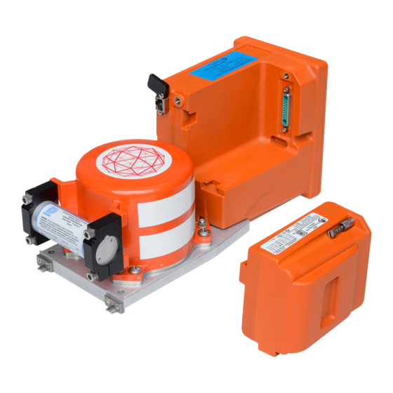
COCKPIT VOICE and DATA RECORDER
DISTRIBUTION STATEMENT:
information and must not, without prior written consent of L3 Aviation Recorders, be used or reproduced
in whole or in part, or communicated to any person except as authorized by L3 Aviation Recorders.
WARNING: This technical data is controlled under the Export Administration Regulations (EAR) ECCN
7E994, and may not be exported to a foreign person, either in the U.S. or abroad, without a license or
exception from the U.S. Department of Commerce.
The document reference is online, please check the correspondence between the online documentation and the printed version.
AVIATION RECORDERS
COMPONENT MAINTENANCE MANUAL
Model FA5000
MODEL FA5000
RECORDER PART NUMBERS:
5001−6103−( ) CVDR
5011−6103−( ) CVDR
5001−6133−( ) CVDR with Video
5003−6103−( ) CVDR
500−4030−000 RIPS
COMPONENT MAINTENANCE MANUAL WITH
ILLUSTRATED PARTS LIST
P/N: 165E5398−00
IN ACCORDANCE WITH
FAA TSO−C123b,−C124b,−C155a,−C177
EUROCAE ED−112
VENDOR CODE: 06141
This document contains L3 Aviation Recorders privileged
23−70−40
Rev. 06
March 16/16
Advertisement
Chapters
Table of Contents
Troubleshooting

Related Manuals for L3 FA5000


Summary of Contents for L3 FA5000
- Page 1 AVIATION RECORDERS COMPONENT MAINTENANCE MANUAL Model FA5000 MODEL FA5000 COCKPIT VOICE and DATA RECORDER RECORDER PART NUMBERS: 5001−6103−( ) CVDR 5011−6103−( ) CVDR 5001−6133−( ) CVDR with Video 5003−6103−( ) CVDR 500−4030−000 RIPS COMPONENT MAINTENANCE MANUAL WITH ILLUSTRATED PARTS LIST P/N: 165E5398−00...
- Page 2 AVIATION RECORDERS COMPONENT MAINTENANCE MANUAL Model FA5000 Model FA5000 Rev. 06 March 16/16 This manual contains date sensitive information. To verify the latest revision level of this manual, visit our document download site at http://www.L−3ar.net. ECopyright 2016 by L-3 Communications Cor- poration, Aviation Recorders End User Statement.
- Page 3 AVIATION RECORDERS COMPONENT MAINTENANCE MANUAL Model FA5000 GENERAL This product and related documentation must be reviewed for familiarization with safety markings and instructions before operation. This instrument was constructed in an ESD (electro–static discharge) protected environ- ment. This is because most of the semiconductor devices used in this instrument are susceptible to damage by static discharge.
- Page 4 AVIATION RECORDERS COMPONENT MAINTENANCE MANUAL Model FA5000 THIS PAGE IS INTENTIONALLY LEFT BLANK 23–70−40 Title Rev. 05 Page iv Use or disclosure of information on this sheet is subject to The document reference is online, please check the correspondence between the online documentation and the printed version.
- Page 5 AVIATION RECORDERS COMPONENT MAINTENANCE MANUAL Model FA5000 HIGHLIGHTS Pages which have been added or revised are outlined below, together with the highlights of Revision 06. Section Page Description i − xxxvii except Front Matter Revised pages to Rev. 06 for xxx, xiv Introduction Description &...
- Page 6 AVIATION RECORDERS COMPONENT MAINTENANCE MANUAL Model FA5000 HIGHLIGHTS Pages which have been added or revised are outlined below, together with the highlights of Revision 05. Section Page Description i − xxxvii except Front Matter Revised pages to Rev. 05 for xxx, xiv Introduction Description &...
- Page 7 AVIATION RECORDERS COMPONENT MAINTENANCE MANUAL Model FA5000 HIGHLIGHTS Pages which have been added or revised are outlined below, together with the highlights of Revision 04. Section Page Description Title Title Page Added RIPS P/N: 500−4030−000 List of FSB’s xiii Added Mod−Dot−2, Improves CAM audio Channel profromance...
- Page 8 AVIATION RECORDERS COMPONENT MAINTENANCE MANUAL Model FA5000 Pages which have been added or revised are outlined below, together with the highlights of Revision 03. Section Page Description Title List of FSB’s Front Matter Introduction Changed part number. Description & Operation Testing &...
- Page 9 AVIATION RECORDERS COMPONENT MAINTENANCE MANUAL Model FA5000 Pages which have been added or revised are outlined below, together with the highlights of Revision 02. Section Page Description Title List of FSB’s Front Matter Introduction Description & Add sentence: To be compliant with TSO−C155a, RIPS must be in-...
- Page 10 AVIATION RECORDERS COMPONENT MAINTENANCE MANUAL Model FA5000 Pages which have been added or revised are outlined below, together with the highlights of Revision 01. Section Page Description Title List of FSB’s Front Matter Introduction Description & Add sentence: To be compliant with TSO−C155a, RIPS must be in-...
- Page 11 AVIATION RECORDERS COMPONENT MAINTENANCE MANUAL Model FA5000 RECORD OF HIGHLIGHTS Issue Revision Date of Comments Change Initial issue Sep. 30/11 Initial issue of CMM. Includes all sections, in ATA100 format. Rev. 01 Oct. 06/11 Add statement on TSO−C155a Compliance Rev. 02 Jul.
- Page 12 AVIATION RECORDERS COMPONENT MAINTENANCE MANUAL Model FA5000 THIS PAGE IS INTENTIONALLY LEFT BLANK 23–70–40 Highlights Rev.05 Page xii Use or disclosure of information on this sheet is subject to May 06/14 the restrictions on the cover page of this document.
- Page 13 AVIATION RECORDERS COMPONENT MAINTENANCE MANUAL Model FA5000 RECORD OF REVISIONS REV. INSERTION REV. INSERTION REV. INSERTION DATE DATE DATE Oct. 06/11 G.M. Jul. 17/12 G.M. Feb. 27/13 M.R. Mar. 21/14 G.M. May 06/14 G.M. March 16/16 C.P . 23–70–40 Record of Revisions Rev.
- Page 14 AVIATION RECORDERS COMPONENT MAINTENANCE MANUAL Model FA5000 THIS PAGE IS INTENTIONALLY LEFT BLANK 23–70–40 Record of Revisions Rev. 05 Page xiv Use or disclosure of information on this sheet is subject to May 06/14 the restrictions on the cover page of this document.
- Page 15 AVIATION RECORDERS COMPONENT MAINTENANCE MANUAL Model FA5000 SERVICE BULLETIN LIST SERVICE BULLETIN DATE EFFECTIVITY DESCRIPTION FA5001 CVDR Aug. 27/13 5001−6103−11 MOD−DOT 02−Improved Main Processor FSB001 which improves CAM audio channel per- 23−70−40−01 formance. FA5001 CVDR May 20/14 5001−6103−11 INTRODUCTION OF SOFTWARE REVI-...
- Page 16 AVIATION RECORDERS COMPONENT MAINTENANCE MANUAL Model FA5000 THIS PAGE IS INTENTIONALLY LEFT BLANK 23–70–40 Service Bulletin Rev. 04 Page xvi Use or disclosure of information on this sheet is subject to Mar. 21/14 the restrictions on the cover page of this document.
- Page 17 AVIATION RECORDERS COMPONENT MAINTENANCE MANUAL Model FA5000 LIST OF EFFECTIVE PAGES Section Page Date Section Page Date Title Page Rev. 06 xxxii Mar. 16/16 Rev. 06 xxxiii Mar. 16/16 Rev. 05 May 06/14 Rev. 06 xxxiv Mar. 16/16 Rev. 06 Mar.
- Page 18 AVIATION RECORDERS COMPONENT MAINTENANCE MANUAL Model FA5000 LIST OF EFFECTIVE PAGES Section Page Date Section Page Date CVR Testing and Troubleshooting FDR Testing and Troubleshooting Rev. 04 Feb. 27/14 Rev. 06 Mar. 16/16 Rev. 04 Feb. 27/14 Rev. 03 Feb. 27/13 Rev.
- Page 19 AVIATION RECORDERS COMPONENT MAINTENANCE MANUAL Model FA5000 LIST OF EFFECTIVE PAGES Section Page Date Section Page Date Disassembly Sep. 30/11 Rev. 05 May 06/14 Rev. 05 May 06/14 Sep. 30/11 Rev. 05 May 06/14 Rev. 06 Mar. 16/16 Rev. 06 Mar.
- Page 20 AVIATION RECORDERS COMPONENT MAINTENANCE MANUAL Model FA5000 THIS PAGE IS INTENTIONALLY LEFT BLANK 23−70−40 List of Effective Pages Rev. 05 Page xx Use or disclosure of information on this sheet is subject to May 06/14 the restrictions on the cover page of this document.
- Page 21 AVIATION RECORDERS COMPONENT MAINTENANCE MANUAL Model FA5000 TABLE OF CONTENTS SUBJECT/DESCRIPTION Page INTRODUCTION GENERAL ..............
-
Page 22: Table Of Contents
AVIATION RECORDERS COMPONENT MAINTENANCE MANUAL Model FA5000 Physical Characteristics .......... - Page 23 AVIATION RECORDERS COMPONENT MAINTENANCE MANUAL Model FA5000 TABLE OF CONTENTS (Continued) SUBJECT/DESCRIPTION Page (10) Crosstalk Audio ...........
- Page 24 ......FA5000 Autotest & Return to Service Check ......
- Page 25 AVIATION RECORDERS COMPONENT MAINTENANCE MANUAL Model FA5000 TABLE OF CONTENTS (Continued) SUBJECT/DESCRIPTION Page CLEANING GENERAL ..............
- Page 26 AVIATION RECORDERS COMPONENT MAINTENANCE MANUAL Model FA5000 TABLE OF CONTENTS (Continued) SUBJECT/DESCRIPTION Page ASSEMBLY GENERAL ..............
- Page 27 AVIATION RECORDERS COMPONENT MAINTENANCE MANUAL Model FA5000 TABLE OF CONTENTS (Continued) SUBJECT/DESCRIPTION Page Electrical Characteristics ..........
- Page 28 AVIATION RECORDERS COMPONENT MAINTENANCE MANUAL Model FA5000 THIS PAGE IS INTENTIONALLY LEFT BLANK 23–70–40 Table of Contents Rev. 06 Page xxviii Use or disclosure of information on this sheet is subject to Mar. 16/16 the restrictions on the cover page of this document.
- Page 29 ....Figure 2. Model FA5000 Cockpit Voice Recorder Part Number Matrix ....
- Page 30 LIST OF FIGURES (Continued) FIGURE TITLE Page Figure 201. ROSE/RI Setup For Testing FA5000 CVDR Recorders ....Figure 202. RI Recorder Status Window Indications .
- Page 31 AVIATION RECORDERS COMPONENT MAINTENANCE MANUAL Model FA5000 LIST OF FIGURES (Continued) FIGURE TITLE Page Figure 901. ROC/7 w/CVDR Automated Test Station Software (CATS) FA5000CVDR TEST SETUP ......... . .
- Page 32 AVIATION RECORDERS COMPONENT MAINTENANCE MANUAL Model FA5000 THIS PAGE IS INTENTIONALLY LEFT BLANK 23–70–40 Table of Contents Rev. 06 Page xxxii Use or disclosure of information on this sheet is subject to Mar. 16/16 the restrictions on the cover page of this document.
- Page 33 ......... . Table 801. Model FA5000 Environmental Characteristics .
- Page 34 AVIATION RECORDERS COMPONENT MAINTENANCE MANUAL Model FA5000 THIS PAGE IS INTENTIONALLY LEFT BLANK 23–70–40 Table of Contents Rev. 06 Page xxxiv Use or disclosure of information on this sheet is subject to Mar. 16/16 the restrictions on the cover page of this document.
- Page 35 CMM covers the 2-hour Video memory storage versions of the FA5000CVDR. The FA5000 is designed as maintenance-free recorder. No periodic adjustments, calibra- tion, or maintenance is required to maintain this unit. The Model FA5000 is considered an “ON CONDITION LRU.”...
- Page 36 AVIATION RECORDERS COMPONENT MAINTENANCE MANUAL Model FA5000 CVDR Cockpit Voice Data Recorder Direct Current EEPROM Electrically Erasable Programmable Read Only Memory EUROCAE European Organization for Civil Aviation Equipment Federal Aviation Administration FDAU Flight Data Acquisition Unit CVDR Flight Data Recorder...
- Page 37 FA5000’s maintenance philosophy is replacement of failed level 2 assemblies. The field replaceable assemblies identified for the FA5000 are the Aircraft Interface PWA, the Main Processor PWA with or with out Video extension card, and the Crash Survivable Memory Unit (CSMU).
-
Page 38: Component Maintenance Manual
DESCRIPTION AND OPERATION This section contains the description and operation information for the Model FA5000 Cockpit Voice Data Recorder. Line art is used to illustrate the unit, its inter- connections and functionality. This section also contains the Model FA5000 Theory of Operation. - Page 39 ASSEMBLY This section contains detailed step-by-step procedures describing the complete as- sembly of the Model FA5000 Solid-State Cockpit Voice Data Recorder. Each major assembly procedure is accompanied with a line art exploded-view of the subassem- bly area which is cross referenced to the applicable Illustrated Parts List (IPL) draw- ing for ordering replacement parts.
-
Page 40: Table 1. Shop Verification
AVIATION RECORDERS COMPONENT MAINTENANCE MANUAL Model FA5000 6. DOCUMENT VERIFICATION All CMM drawings, illustrations, wiring diagrams, and block diagrams were validated against existing engineering source material. All Testing & Fault Isolation, Disassembly and Assembly procedures have been verified against the actual performance of the unit under test conditions as indicated in Table 1 below. - Page 41 AVIATION RECORDERS COMPONENT MAINTENANCE MANUAL Model FA5000 8. PART NUMBER FORMATTING L−3AR does not delineate its part numbers by special characters, such as the “−” dash character. L−3AR considers its part numbers with or without the use of special characters to be the same, for example, there is no difference between part number 266−E0305−00, 266E0305−00, or...
- Page 42 AVIATION RECORDERS COMPONENT MAINTENANCE MANUAL Model FA5000 THIS PAGE IS INTENTIONALLY LEFT BLANK 23−70–40 Introduction Initial Issue Page 8 Use or disclosure of information on this sheet is subject to Rev.06 Page 8 Sep. 30/11 the restrictions on the cover page of this document.
- Page 43 This Component Maintenance Manual describes the Model FA5000, Cockpit Voice Data Recorder (CVDR). FA5000CVDR, P/N: 5001-6103−( ), 5011-6103-( ), 5001-6133-( )(with video) and 5003-6103−( ). The FA5000 is a highly reliable recorder that is designed to meet the performance requirements of ED−112. The Model FA5000 recorder is designed as a maintenance free recorder.
-
Page 44: Figure 2. Model Fa5000 Cockpit Voice Recorder Part Number Matrix
The current configurations of the FA5000s are listed with its specific part number in the IPL Section Figure 2. The specific configuration FA5000 part number is constructed as shown below: Figure 2. Model FA5000 Cockpit Voice Recorder Part Number Matrix 23–70−40... - Page 45 (Ethernet, Wireless), with the GSE operator interface via an ordinary web browser. The software running on the Model FA5000 will process the incoming audio data, flight data, and DataLink messages into packets that get stored in the CSMU. The software will also provide built-in test functionality that will automatically perform checks of the hard- ware and software to indicate whether the system is operating normally.
- Page 46 AVIATION RECORDERS COMPONENT MAINTENANCE MANUAL Model FA5000 ARINC 429 UTC Rotor Speed Discretes: Bulk-Erase Push-to-Test Record On Stop Record CVR Ident FDR Inhibit FDR Rate DataLink Valid System Outputs: Audio Monitor Discretes: CVR Fault FDR Fault DataLink Fault Push-to-Test Pass/Fail 23–70−40...
-
Page 47: Figure 3. Cvdr Block Diagram
(PAL B) Figure 3. CVDR Block Diagram Figure 3 – Recorder Data Flow Diagram shows the data flow diagram for the Model FA5000. The software data flow diagram shows the relationship between the hardware 23–70−40 Description and Operation Initital Issue Page 5 Use or disclosure of information on this sheet is subject to Sep. - Page 48 DataLink messages will be kept along with the most recent 25 hours of flight data. The Model FA5000 will be able to be loaded via the TCP/IP interface used by the GSE task. This task will report a checksum of the loaded code to ensure the integrity of the newly loaded software.
-
Page 49: Table 1. Cockpit Area Microphone Pre-Amplifier Input Attenuation Decode
Signal Directory Aircraft Interface PWA to Aircraft, J1 Signal Directory for the FA5000 Cockpit Voice and Data Recorder MIL-C-38999 Interface defines the FA5000 CVDR equipment pin−out utilizing a MS27508E16F35P, MIL-C-38999, Series II connector with PCB tails (Amphenol 10-565998-198N). The air- craft side mating connector is an MS27473E16F35S (or equivalent). - Page 50 Referenced to the Signal Ground. Analog_Audio_Input4 Unused. Differential analog input, line high. Referenced to the Signal Ground. Not used in the FA5000, circuitry not populated on AI PWA. Floating input configuration is accommodated by soft ware programmed tristate capability within the Audio CODEC.
- Page 51 AVIATION RECORDERS COMPONENT MAINTENANCE MANUAL Model FA5000 ARINC429_RCV_B1 Standard ARINC 429 differential input – Bside. Assigned to ATC Digital Input. Referenced to the Signal Ground. ARINC429_RCV_A2 Standard ARINC 429 differential input – Aside. Referenced to the Signal Ground. Not used in the FA5001, cir...
- Page 52 AVIATION RECORDERS COMPONENT MAINTENANCE MANUAL Model FA5000 Discrete_Input_Power +18.5 volts DC, diode isolated power used pull up the input discrete in order to configure them for shunt configuration. Referenced to the Signal Ground. Discrete_Input1 ATE Present conditioned as the CVR REPLAY INHIBIT FDR INHIBIT shunt discrete input to the 12bit ADC convert...
- Page 53 AVIATION RECORDERS COMPONENT MAINTENANCE MANUAL Model FA5000 Discrete_Input7 Conditioned ERASE CVR INPUT A series discrete input to the 12bit ADC converter. The discrete state is determ ined as high or low by comparison to in ternally programmed thresholds. Refer enced to the Signal Ground.
- Page 54 AVIATION RECORDERS COMPONENT MAINTENANCE MANUAL Model FA5000 Discrete_Input13 Conditioned shunt discrete input to the 12bit ADC converter. The discrete state is determined as high or low by compar ison to internally programmed thresholds. Referenced to the Signal Ground. No circuitry exists on the AI PWA to support this signal.
- Page 55 AVIATION RECORDERS COMPONENT MAINTENANCE MANUAL Model FA5000 fpga_discrete_Output2 3.3VDC CMOS output pulled high to 3.3 volts by default. The CMOS low voltage output, V does not exceed 0.4VDC. The signal controls an NFET gate hav ing a 0.7VDC minimum voltage input threshold.
- Page 56 AVIATION RECORDERS COMPONENT MAINTENANCE MANUAL Model FA5000 fpga_RES_FDR_STATUS_C 3.3VDC CMOS output pulled high to 3.3 ontrol_set volts by default. The CMOS low voltage output, V does not exceed 0.4VDC. The signal controls an NFET gate hav ing a 0.5VDC minimum voltage input threshold.
-
Page 57: Table 4. Hold Up Capacitor Voltage Return To Cpu Pwa, J7
AVIATION RECORDERS COMPONENT MAINTENANCE MANUAL Model FA5000 B2, C2, Signal Ground D3, E3, G10, G11, H10, C11, Chassis Ground AI PWA Connector: HM-H088FL1-8CS1-TG30 Processor PWA Connector: HM-S088FL1-8AP1-TG30 Hold Up Capacitor Voltage to Aircraft Interface PWA, J2 Table 3. - Page 58 Model FA5000 Video Connector, PWA: Amphenol 903-523J-71P Video Connector Mate: Connex 142101 5. FA5000 SPECIFICATIONS Specifications for the Model FA5001 have been developed in close coordination with Aerospace Industry regulatory agencies. As such, the FA5001 meets or exceeds the re- quirements of technical standard order TSO–C123b, TSO–C124b, TSO−C155a, TSO−...
-
Page 59: Physical Characteristics
Model FA5000CVDR Installation and Opera- tion Instruction Manual, p/n: 165E5327-01. The Model FA5000 is an environmentally hardened unit housed in an trayless mounted short box painted international orange. The FA5000 does not require external shock mounting for installation into the aircraft. - Page 60 AVIATION RECORDERS COMPONENT MAINTENANCE MANUAL Model FA5000 AIRCRAFT INTERFACE FUNCTION SIGNAL NAME ATE PRESENT ATE PRESENT controls Record Enable and CVR Replay Inhibit/FDR Inhibit functions. When ATE is not detected, all recording is enabled and CVR Replay is disabled and FDR Inhibit is inactive.
- Page 61 AVIATION RECORDERS COMPONENT MAINTENANCE MANUAL Model FA5000 CESSATION OF Ground logic applied to this pin (or loss of aircraft RECORDING power, whichever occurs first) activates a CV/FDR internal timer that stops the recorder from record ing after 10 minutes. Removal of the ground logic when the recorder is powered will cause the re...
- Page 62 AVIATION RECORDERS COMPONENT MAINTENANCE MANUAL Model FA5000 CHANNEL 3 INPUT LOW Channel 3 audio differential input signal low; 150 Hz to 3.5 kHz bandwidth, 3V RMS maximum. Im pedance 5K ohm minimum. CHANNEL 3 INPUT HIGH Channel 3 audio differential input signal high; 150 Hz to 3.5 kHz bandwidth, 3V RMS maximum.
- Page 63 AVIATION RECORDERS COMPONENT MAINTENANCE MANUAL Model FA5000 FDR DATA INPUT ARINC ARINC 717 differential serial flight data input sig 717 LOW nal, Line B, received from an aircraft data acquisi tion unit. Format is defined in ARINC Characterist ics 573, 717, and 747. Data rate of 64 wps, 128 wps, 256 wps, or 512 wps is determined by FDR DATA RATE A and FDR DATA RATE B.
- Page 64 AVIATION RECORDERS COMPONENT MAINTENANCE MANUAL Model FA5000 +28VDC INPUT +28VDC power supply secondary input per SECONDARY TNX131AF329E10, Section 3.4.2.5 (FAR 29.1459 (a) (6)) AREA MICROPHONE Connected to Pin 38, POWER RETURN AREA_MICROPHONE_SIGNAL LOW, through a 0 Ohm resistor. AREA MICROPHONE...
- Page 65 AVIATION RECORDERS COMPONENT MAINTENANCE MANUAL Model FA5000 COCKPIT AREA MIC INPUT Signal ground reference output for the grounding ATTENUATION COMMON of pins 48, 49, 50 individually, or combined, to set (GND) the microphone gain selection in voice recorders having an internal microphone preamplifier. See Table A2 below.
- Page 66 AVIATION RECORDERS COMPONENT MAINTENANCE MANUAL Model FA5000 THIS PAGE IS INTENTIONALLY LEFT BLANK 23–70−40 Description and Operation Initital Issue Page 24 Use or disclosure of information on this sheet is subject to Sep. 30/11 The document reference is online, please check the correspondence between the online documentation and the printed version.
-
Page 67: Cvr Testing And Troubleshooting
17TES0420. The CATS software is contained on the L−3AR Read-Out Center/7 (ROC/7), p/n: 17TES0700 and is used in conjunction with the L−3AR Recorder Interface Unit (RIU), p/n: 17TES0710. Testing for the Model FA5000 CVR is based upon an automated operational test procedure. The automated test procedure may serve as an acceptance criteria for the unit, as well as provide pointers to probable malfunctioning assemblies in the event that the unit is not functioning properly. -
Page 68: Model Fa5000Cvdr Recorder In-Service Checkout
When it has been deter- mined that an assembly is faulty, it should be removed from service, properly packaged, and returned to L3 Communications, Aviation Recorders for repair or replacement. No troubleshooting procedure is provided for any of these assemblies. Attempting field repair on any of these assemblies will void their warranty. - Page 69 AVIATION RECORDERS COMPONENT MAINTENANCE MANUAL Model FA5000 Connect the DC power cable (17TES0412) from the DC Power connector (J8) on the rear of the RIU to a DC power supply that can generate 28 Volts 1 Amp. Plug the cable (17TES0418) into the rear of the recorder to be tested. Plug the SCSI connector into “Rear Connector Intfc”...
-
Page 70: Table 101. 17Tes0700 Readout Center/7 (Roc/7)
Ethernet Cross−over (REQUIRED) 0249800386 Cable Assembly, 17TES0426 Speakers - 2 (OPTIONAL) * Items are included in ROC/7 Kit but not used with Model FA5000 testing. 23–70−40 Testing & Fault Isolation Rev. 04 Page 104 Rev.06 Page 104 Use or disclosure of information on this sheet is subject to Feb. -
Page 71: Figure 101. Roc/7 W/Cvdr Automated Test Station Software (Cats)
AVIATION RECORDERS COMPONENT MAINTENANCE MANUAL Model FA5000 J4 USB 4‐PIN CVDR AUTOMATED TEST RIU UNIVERSAL SERIAL SOFTWARE (CATS) BUS INTERFACE 17TES0415 17TES0420 RIU DC POWER INPUT POWER 17TES0412 (DC)- J8 RIU AC POWER INPUT INPUT SELECT 17TES0411 (AC)- J7 RECORDER INTERFACE... -
Page 72: Read−Out Center/7 (Roc/7) − Sound Card Setup
AVIATION RECORDERS COMPONENT MAINTENANCE MANUAL Model FA5000 READ−OUT CENTER/7 (ROC/7) − Sound Card Setup Double−click the CVDR Test icon on the ROC to start the software. The applic- ation will launch with the Channels control screen displayed, as illustrated in Figure 102. -
Page 73: Figure 103. Volume Control
AVIATION RECORDERS COMPONENT MAINTENANCE MANUAL Model FA5000 Figure 103. Volume Control Under Applications, click Sound Systems, then click the Recording tab. This will display the Sound control window illustrated in Figure 104. Figure 104. Sound Control, Recording 23–70−40 Testing & Fault Isolation Rev. -
Page 74: Figure 105. Line−In Properties, Line−In Level
AVIATION RECORDERS COMPONENT MAINTENANCE MANUAL Model FA5000 Highlight and select Line−in. Click on Properties. Select the Levels tab. Figure 105. Line−In Properties, Line−In Level Make sure that the Line−In level is set at 100 (move the Line−In slider to maximum.) Click on OK. -
Page 75: Figure 106. Sound, Playback Devices
AVIATION RECORDERS COMPONENT MAINTENANCE MANUAL Model FA5000 Figure 106. Sound, Playback Devices (10) Highlight Speakers. (11) Click on Properties. (12) Select the Levels tab. 23–70−40 Testing & Fault Isolation Rev. 04 Page 109 Use or disclosure of information on this sheet is subject to Feb. -
Page 76: Figure 107. Speaker Properties, Levels
AVIATION RECORDERS COMPONENT MAINTENANCE MANUAL Model FA5000 Figure 107. Speaker Properties, Levels (13) Make sure Playback Control is set at 100. (move the Playback Control slider to its maximum setting) (14) Make sure that the four remainingVolume slider levels do not need modification since these input volumes have been muted. -
Page 77: Figure 108. Volume Mixer, Speaker Levels
AVIATION RECORDERS COMPONENT MAINTENANCE MANUAL Model FA5000 Figure 108. Volume Mixer, Speaker Levels (17) In the Volume Mixer, make sure both sliders are all the way up. (18) Close the Volume Mixer. 23–70−40 Testing & Fault Isolation Rev. 04 Page 111 Use or disclosure of information on this sheet is subject to Feb. -
Page 78: Read−Out Center/7 (Roc/7) − Cats Autotest
AVIATION RECORDERS COMPONENT MAINTENANCE MANUAL Model FA5000 READ−OUT CENTER/7 (ROC/7) − CATS Autotest CAUTION:Ensure power is removed from the recorder before proceeding. If the cable, p/n: 17TES0418 is connected to rear of the unit with the power applied to the RIU, the RIU may be damaged. -
Page 79: Figure 109. Cats, Connecting Pop-Up
AVIATION RECORDERS COMPONENT MAINTENANCE MANUAL Model FA5000 NOTE: This will load the Altera chip in the RIU unit. Observe the “con- necting to the recorder” status window appears. Observe Figure 109. CATS, Connecting Pop-Up On the tool bar, select Power ON. -
Page 80: Figure 111. Cats, Start Test Toggle
AVIATION RECORDERS COMPONENT MAINTENANCE MANUAL Model FA5000 On the tool bar, select Start Test. Figure 111. CATS, Start Test Toggle In the “Test Mode and Options” dialog box, select either Return−to−Ser- vice or Selectable Test Options, then click on OK. -
Page 81: Figure 113. Cats, Cvdr Test Confirmation
AVIATION RECORDERS COMPONENT MAINTENANCE MANUAL Model FA5000 NOTE: Figure 113 is only displayed if “Selectable Test Option” is cho- sen from the CATS, Test Mode and Options Screen. Figure 113. CATS, CVDR Test Confirmation NOTE: Follow the instructions displayed in the confirmation window. -
Page 82: Figure 115. Cats, Power Test Input
AVIATION RECORDERS COMPONENT MAINTENANCE MANUAL Model FA5000 Figure 115. CATS, Power Test Input Read the current DC amps value from the built-in multimeter on the power supply or from the inline RMS multimeter. And enter in the value in amps in window and click on OK. -
Page 83: Figure 117. Cats, Cvdr Fault History Log
AVIATION RECORDERS COMPONENT MAINTENANCE MANUAL Model FA5000 Figure 117. CATS, CVDR Fault History Log Click on Yes on the dialog box to clear the fault logs. Figure 118. CATS, CVDR Clear Fault Log Confirmation Observe the Fault History Log window appears. Select Print if you want to save the fault history or Close to continue. -
Page 84: Figure 119. Cats, Cvdr Fault History Log
AVIATION RECORDERS COMPONENT MAINTENANCE MANUAL Model FA5000 Figure 119. CATS, CVDR Fault History Log Click on Yes. The autotest will now proceed in completing the autotest which will take approximately 30 minutes or less. Figure 120. CATS, Continue Test Confirmation At the end of the test, save the report by selecting File =>... -
Page 85: Figure 121. Cats, Test Results Screen
AVIATION RECORDERS COMPONENT MAINTENANCE MANUAL Model FA5000 Figure 121. CATS, Test Results Screen If the autotest is successful, power off the recorder from the CATS menu bar. Turn 28VDC power off and remove the crossover and RIU cables from the recorder. -
Page 86: Read Out Center/7 (Roc/7) − Autotest Descriptions
AVIATION RECORDERS COMPONENT MAINTENANCE MANUAL Model FA5000 READ OUT CENTER/7 (ROC/7) − Autotest Descriptions The following provides detailed descriptions of the test performed during the autotest function. Power Test Test Prompts the user for DC power usage as in the following DC example: Please remove the front panel cable from the recorder now and click ”OK”. -
Page 87: Bulk Erase
AVIATION RECORDERS COMPONENT MAINTENANCE MANUAL Model FA5000 Bulk Erase Part 1 – record audio out and verify 400 Hz bulk erase tone. Part 2 – record audio out and verify absence of bulk erase tone during rotor data output. Part 3 – record audio out and verify absence of bulk erase with recording disabled. -
Page 88: Channel Balance
AVIATION RECORDERS COMPONENT MAINTENANCE MANUAL Model FA5000 08:03:52 PASSED Rotor Speed 6000 Hz (Expected 4 patterns > 5880.0 Hz < 6120.0 Hz) Results = 5998.0 Hz, 6026.4 Hz, 6026.4 Hz, 6026.4 Hz 08:04:03 PASSED Rotor Speed 7 Hz (Expected 4 patterns > 6.9 Hz < 7.1 Hz) Results = 7.0 Hz, 7.0 Hz, 7.0 Hz, 7.0 Hz... -
Page 89: Signal To Noise And Distortion
AVIATION RECORDERS COMPONENT MAINTENANCE MANUAL Model FA5000 08:08:12 Frequency Resp 5000 Hz 0.5 ref Results = HQC 4.9 dBV 08:08:23 Frequency Resp 6000 Hz 0.5 ref Results = HQC 4.9 dBV 08:08:23 PASSED Frequency Resp (All within 6 dB) Signal to Noise and Distortion Record simulated data at each of the following frequencies once at 1.0 reference... -
Page 90: Crosstalk Data
AVIATION RECORDERS COMPONENT MAINTENANCE MANUAL Model FA5000 (10) Crosstalk Audio Record simulated 1000 Hz data for each channel 1,2,3 & 4 and calculate difference between driven and non−driven channels. Verify difference is less than −40 dB. Example report message(s): 08:41:34 PASSED Crosstalk (Audio) 1000 Hz 1.0 ref (Expected Driven − Non−... -
Page 91: Fsk Time
AVIATION RECORDERS COMPONENT MAINTENANCE MANUAL Model FA5000 (12) FSK Time This test cycles power to recorder to reset for FSK input then records simulated 16000 sps FSK data and then simulated GMT 429 data (label 150) first with channel 1 output and again with channel 3 output. It verifies 9 good FSK data patterns and a switch to 9 good GMT 429 data patterns for each channel 1 and channel 3. -
Page 92: Shutdown
AVIATION RECORDERS COMPONENT MAINTENANCE MANUAL Model FA5000 (15) Shutdown Remove recorder power and verify recorder continues to operate for > 9 and < 10 minutes after power is removed and shutdown is terminated following a push to test. Part 1 – enable delayed shutdown. -
Page 93: Oms
AVIATION RECORDERS COMPONENT MAINTENANCE MANUAL Model FA5000 (18) OMS Read the OMS status words and verify CVR fault status and CVR part number and serial number. Example report message(s): 08:59:00 PASSED OMS Part 1 (Expected OMS Status to match) 08:59:10 PASSED OMS Part 2 (Expected OMS Part and Serial Numbers to match) Results = pn2100−1025−22 sn000000000... -
Page 94: Read−Out Center/7 (Roc/7) − Audio Download & Playback
AVIATION RECORDERS COMPONENT MAINTENANCE MANUAL Model FA5000 READ−OUT CENTER/7 (ROC/7) − AUDIO DOWNLOAD & PLAYBACK NOTE: ROSE 4.0 or higher on a ROC or RAU is recommended to download directly from a CVR and convert audio into a .WAV for playback. Re- fer to the Read-Out Support Equipment / Recorder Interface Software version 4.0 or Higher Operator’s Manual, p/n 165E1696-03, to Re-... -
Page 95: Table 102. Underwater Locator Beacon Test Using L−3Ar Test Set P/N: 17Tes0015
AVIATION RECORDERS COMPONENT MAINTENANCE MANUAL Model FA5000 TEST THE UNDERWATER LOCATOR BEACON (ULB) The 17TES0015 is a battery operated heterodyne type receiver that operates at an ul- trasonic frequency of 37.5 kHz. The test set is a self-contained, hand held functional tester for testing 90−Day and 30−Day Underwater Locator Beacons. - Page 96 AVIATION RECORDERS COMPONENT MAINTENANCE MANUAL Model FA5000 THIS PAGE IS INTENTIONALLY LEFT BLANK 23–70−40 Testing & Fault Isolation Rev. 04 Page 130 Use or disclosure of information on this sheet is subject to Feb. 27/14 the restrictions on the cover page of this document.
-
Page 97: Fdr Function Testing And Fault Isolation
1. GENERAL This section provides the operational acceptance test, functional test, troubleshooting, and fault isolation procedures necessary to maintain the FA5000 Cockpit Voice and Data Recorder FDR function. The operational test serves as acceptance criteria for a Return- To-Service checkout of the recorder, as well as, provides pointers to further trouble- shooting and fault isolation procedures and probable cause(s) analysis in the event of fail- ure. -
Page 98: Recorder Test States
Model FA5000 Recorder Test States It is important to have a clear understanding of the FA5000 software operating states and their indications that the FA5000CVDR can go through when simulating data to the recorder in the testing environment. This paragraph briefly explains these states and what to expect when switching modes. - Page 99 Cross−over GSE cable assembly, power up the ROC/7 (cold boot) and activate the ROSE/RI software before applying power to the FA5000CVDR. Always apply power to the FA5000 Recorder before activating the ROSE Test Flight Recorder Function. After setting Data Type/Rate, wait for approximately 15 seconds until the...
-
Page 100: Fa5000Cvdr Bench Test Procedures
AVIATION RECORDERS COMPONENT MAINTENANCE MANUAL Model FA5000 Be patient when switching modes and monitoring the recorder status changes in the Status Window. It takes the FA5000CVDR up to 5 sec- onds to stabilize on a mode change and it takes ROSE a maximum of 15 seconds to refresh and display the current operating state of the recorder. -
Page 101: Figure 201. Rose/Ri Setup For Testing Fa5000Cvdr Recorders
Figure 201. ROSE/RI Setup For Testing FA5000CVDR Recorders Refer to Figure 201 for the FA5000FDR Test Setup Diagram. The FA5000FDR re- ceives its control and operating power through the FA5000 Recorder Interface (RI) Cable Assembly, p/n: 17TES0057, supplied from a user’s external source. The RI 23–70−40... -
Page 102: Fault Condition Reset
AC and DC simultaneously). At the Power source, while monitoring the wattmeter, apply supply voltage of +28 Vdc to the Recorder. After 5 seconds, observe that the FA5000 is consuming no more than 12 watts (True Power). NOTE: True Power is measured with a wattmeter. To obtain True Power with a volt and current meter use the fol- lowing formula: Vrms X Irms = Apparent Power. -
Page 103: Fa5000Cvdr Recorder Initialization Check
Interface when ROSE is started”, and click the Connect button. From the ROSE Main menu, click the Select Aircraft Configuration button. Use the scroll arrow to highlight and click on the FA5000 ARINC 573 and 717, 64 WPS Test Database. - Page 104 AVIATION RECORDERS COMPONENT MAINTENANCE MANUAL Model FA5000 (12) At the ROSE Main menu, click the Test Flight Recorder button. This produces the Test Flight Recorder window. (13) At the Recorder Events Block in the Test Flight Recorder window, click the Display Fault History button.
-
Page 105: Loss Of Input Data Or Synchronization Bit Check
500X−6133−11 840E5497−06 9641 NOTE: If the version of FA5000 operating software changes, then checksum value will change. The new checksum value will be provided in the FSB which documents the recorder software revision. Loss of Input Data or Synchronization BIT Check... -
Page 106: Fa5000 Autotest & Return To Service Check
(15) Observe that the Status Window displays: “FAULT” “NOT RECORDING” in Red. (16) Proceed with the Autotest. FA5000 Autotest & Return to Service Check The ROSE Autotest checks the two independent data paths of the FA5000CVDR: 1) Monitor data from the Aircraft Interface input through the Acquisition Processor’s 23–70−40... - Page 107 AVIATION RECORDERS COMPONENT MAINTENANCE MANUAL Model FA5000 Flight Data Processor and out to the GSE; and 2) Stored data from the Aircraft Inter- face to the Acquisition Processor’s Flight Data Processor onto the Store Manager Processor then to the flash memory devices in the CSMU and then out to the GSE.
-
Page 108: Figure 203. Recorder Automatic Test Information Pop−Up Screen
AVIATION RECORDERS COMPONENT MAINTENANCE MANUAL Model FA5000 Scroll Arrow Figure 203. Recorder Automatic Test Information Pop−Up Screen NOTE: The User can select one of two test duration options; however for this test procedure, use only the Single Pass Test Option. -
Page 109: Set Final Memory Marker
AVIATION RECORDERS COMPONENT MAINTENANCE MANUAL Model FA5000 Successful completion of data dump verification. PASSED - Recorder automatic test completed with success. Figure 204. RI Recorder Status Autotest Indication Once autotest is completed, observe in the status window the following message: “Automatic Recorder Test − PASSED.” in blue. - Page 110 AVIATION RECORDERS COMPONENT MAINTENANCE MANUAL Model FA5000 Within approximately 15 seconds, observe the Status Window displays: “OK” “RECORDING” in blue. In Recorder Events block, click the Set Memory Marker button to set a memory marker in the recorder under test prior to installation in the aircraft.
-
Page 111: Table 203. Underwater Locator Beacon Test Using L−3Ar Test Set P/N: 17Tes0015
AVIATION RECORDERS COMPONENT MAINTENANCE MANUAL Model FA5000 TEST THE UNDERWATER LOCATOR BEACON (ULB) The 17TES0015 is a battery operated heterodyne type receiver that operates at an ul- trasonic frequency of 37.5 kHz. The test set is a self-contained, hand held functional tester for testing 90−Day and 30−Day Underwater Locator Beacons. -
Page 112: Table 204. Aircraft Interface Troubleshooting Chart
AVIATION RECORDERS COMPONENT MAINTENANCE MANUAL Model FA5000 Table 204. Aircraft Interface Troubleshooting Chart Signal Type Signal Function Failure Mode Local Effect End Effect Differential ATE Ethernet TX () The signal path is ATE Ethernet TX () Unable to perform in... - Page 113 AVIATION RECORDERS COMPONENT MAINTENANCE MANUAL Model FA5000 Table 204. Aircraft Interface Troubleshooting Chart (Continued) Signal Type Signal Function Failure Mode Local Effect End Effect Audio O/P () Audio Output (Monit The signal path is No audio (voice) is Unable to monitor au...
- Page 114 AVIATION RECORDERS COMPONENT MAINTENANCE MANUAL Model FA5000 Table 204. Aircraft Interface Troubleshooting Chart (Continued) Signal Type Signal Function Failure Mode Local Effect End Effect Discrete FDR Status The signal path is Incorrect FDR Status The FDR Status signal open The FDR always indic...
- Page 115 AVIATION RECORDERS COMPONENT MAINTENANCE MANUAL Model FA5000 Table 204. Aircraft Interface Troubleshooting Chart (Continued) Signal Type Signal Function Failure Mode Local Effect End Effect ARINC 429 ARINC 429 Output The signal path is Loss of ability to record Unable to record O/P ()
- Page 116 AVIATION RECORDERS COMPONENT MAINTENANCE MANUAL Model FA5000 Table 204. Aircraft Interface Troubleshooting Chart (Continued) Signal Type Signal Function Failure Mode Local Effect End Effect Differential FDR Data Output The signal path is Disrupted FDR Data Disrupted FDR Data ARINC717 ()
- Page 117 AVIATION RECORDERS COMPONENT MAINTENANCE MANUAL Model FA5000 Table 204. Aircraft Interface Troubleshooting Chart (Continued) Signal Type Signal Function Failure Mode Local Effect End Effect Differential FDR Data Output The signal path is Disrupted FDR Data Disrupted FDR Data ARINC717 ARINC 717 High...
- Page 118 AVIATION RECORDERS COMPONENT MAINTENANCE MANUAL Model FA5000 Table 204. Aircraft Interface Troubleshooting Chart (Continued) Signal Type Signal Function Failure Mode Local Effect End Effect Discrete I/P 24dB CAM Input At The signal path is No Effect No Effect tenuation open Discrete I/P 24dB CAM Input At...
-
Page 119: Table 205. Main Processor Troubleshooting Chart
AVIATION RECORDERS COMPONENT MAINTENANCE MANUAL Model FA5000 Table 205. Main Processor Troubleshooting Chart Item Function Type Failure Local Effect Next Effect End Effect Mode A001 Watch Dog Timer; Over/Under The DSP fails: The MP PWA The CVDR fails to operate −... - Page 120 AVIATION RECORDERS COMPONENT MAINTENANCE MANUAL Model FA5000 Table 205. Main Processor Troubleshooting Chart (Continued) Item Function Type Failure Local Effect Next Effect End Effect Mode Watch Dog Timer; Single Event The FPGA ini- The MP PWA The CVDR initially does not oper- ARINC 429 RX/TX;...
- Page 121 AVIATION RECORDERS COMPONENT MAINTENANCE MANUAL Model FA5000 Table 205. Main Processor Troubleshooting Chart (Continued) Item Function Type Failure Local Effect Next Effect End Effect Mode Non−Volatile Memory: Over/Under The SEEP- The MP PWA The CVDR PWA fails to oper- Configuration and Error...
- Page 122 AVIATION RECORDERS COMPONENT MAINTENANCE MANUAL Model FA5000 Table 205. Main Processor Troubleshooting Chart (Continued) Item Function Type Failure Local Effect Next Effect End Effect Mode Non−Volatile Memory Electrical In- Software glitch The MP PWA The CVDR does not operate terference...
- Page 123 AVIATION RECORDERS COMPONENT MAINTENANCE MANUAL Model FA5000 Table 205. Main Processor Troubleshooting Chart (Continued) Item Function Type Failure Local Effect Next Effect End Effect Mode Audio I/P Audio I/P Ch No Audio to Ch 1 is unable Ch 1 is unable to record audio...
- Page 124 AVIATION RECORDERS COMPONENT MAINTENANCE MANUAL Model FA5000 Table 205. Main Processor Troubleshooting Chart (Continued) Item Function Type Failure Local Effect Next Effect End Effect Mode Audio I/P Audio I/P Audio CODEC No audio tone No Effect Tone Test 4 receives/re-...
- Page 125 AVIATION RECORDERS COMPONENT MAINTENANCE MANUAL Model FA5000 Table 205. Main Processor Troubleshooting Chart (Continued) Item Function Type Failure Local Effect Next Effect End Effect Mode Audio I/P Audio I/P Audio CODEC No audio tone No Effect Tone Test 1 receives/re-...
- Page 126 AVIATION RECORDERS COMPONENT MAINTENANCE MANUAL Model FA5000 Table 205. Main Processor Troubleshooting Chart (Continued) Item Function Type Failure Local Effect Next Effect End Effect Mode Audio I/P − Power E020 The CAM The power is Loss of Cockpit Loss of Cockpit Area Micro- −...
- Page 127 AVIATION RECORDERS COMPONENT MAINTENANCE MANUAL Model FA5000 Table 205. Main Processor Troubleshooting Chart (Continued) Item Function Type Failure Local Effect Next Effect End Effect Mode G023 UART1 TxD The UART1 There is no The MP PWA Communication is disrupted −...
- Page 128 AVIATION RECORDERS COMPONENT MAINTENANCE MANUAL Model FA5000 Table 205. Main Processor Troubleshooting Chart (Continued) Item Function Type Failure Local Effect Next Effect End Effect Mode UART0 rxD The UART0 There is no The MP PWA Communication is disrupted RxD RIPS is...
- Page 129 AVIATION RECORDERS COMPONENT MAINTENANCE MANUAL Model FA5000 Table 205. Main Processor Troubleshooting Chart (Continued) Item Function Type Failure Local Effect Next Effect End Effect Mode Differential ARINC757 Data I/P LO Loss of ability Unable to re- Unable to record good ARINC (−)
-
Page 130: Table 206. Csmu Troubleshooting Chart
AVIATION RECORDERS COMPONENT MAINTENANCE MANUAL Model FA5000 Table 206. CSMU Troubleshooting Chart Item ID Function Type Failure Mode Local Effect Next Effect End Effect 0001A − Watch Dog Timer; Over/Under The FPGA does not The CVDR The CVDR does not operate FPGA CSMU Interface;... - Page 131 AVIATION RECORDERS COMPONENT MAINTENANCE MANUAL Model FA5000 Table 206. CSMU Troubleshooting Chart(Continued) Item ID Function Type Failure Mode Local Effect Next Effect End Effect Non−Volatile Over/Under The Flash Memory The CSMU fails The CVDR does not operate Memory Voltage fails: unable to store...
- Page 132 AVIATION RECORDERS COMPONENT MAINTENANCE MANUAL Model FA5000 THIS PAGE IS INTENTIONALLY LEFT BLANK 23–70−40 FDR Function Testing & Fault Isolation Rev. 03 Page 236 Rev.06 Page 236 Use or disclosure of information on this sheet is subject to Feb. 27/13 The document reference is online, please check the correspondence between the online documentation and the printed version.
-
Page 133: Disassembly
1. GENERAL This section contains the information required to disassemble the Model FA5000 Record- ers. Access to the major assemblies within the Model FA5000 is described such that there is minimal disturbance to other assemblies. Extreme care should be exercised when removing these assemblies. -
Page 134: Model Fa5000 Disassembly Instructions
Recorder Independent Power Supply (RIPS) Removal 3. MODEL FA5000 DISASSEMBLY INSTRUCTIONS Special tools, fixtures, and equipment that are needed to disassemble and repair the Model FA5000 are listed in Figure 901. NOTE: Numbers shown in parentheses in the following text and figures are the Illustrated Parts List (IPL) figure number followed by the IPL item number for a particular part;... -
Page 135: (See Figure 4 Or Ipl Figure 1, Item 155A/B)
Remove Underwater Locator Beacon (See Figure 302 or IPL Figure 1, Item 155A/B) The Underwater Locator Beacon (ULB) is mounted on the Model FA5000’s CSMU front bracket with the beacon water switch facing to the left (refer to Figure 302, 1–150). - Page 136 AVIATION RECORDERS COMPONENT MAINTENANCE MANUAL Model FA5000 CAUTION ALL APPLICABLE DEPARTMENT OF TRANSPORTATION (DOT), INTERNATIONAL AIR TRANSPORT ASSOCIATION (IATA) OR IMDG THE INTERNATIONAL MARITIME DANGEROUS GOODS REGULATIONS MUST BE FOLLOWED. IT IS THE RESPONSIBILITY OF THE PARTY PURCHASING, HANDLING, RECEIVING OR...
-
Page 137: Crash-Survivable Memory Unit (Csmu) Removal (See Figure 302 Or Ipl Figure 1, Item 120)
Crash-Survivable Memory Unit (CSMU) Removal (See Figure 303 or IPL Figure 1, Item 120) The Model FA5000’s CSMU is mounted to the top of the recorder chassis by (6) Flat- head screws. It interfaces to the Main Processor (MP) PWA through the Memory In- terface Cable assembly attached to the J−3 connector Main Processor PWA. - Page 138 AVIATION RECORDERS COMPONENT MAINTENANCE MANUAL Model FA5000 Remove the two screws (1−135) used to secure CSMU cable (1−120) connect- or to the MP PWA (1−50) and remove CSMU cable connector and the seal pad (1−140). NOTE: Ensure that the CSMU is support before proceeding.
-
Page 139: Figure 303. Csmu Memory Assembly Removal Diagram
AVIATION RECORDERS COMPONENT MAINTENANCE MANUAL Model FA5000 (1−110) (1−125) (1−120) (REF) (REF) (1−115) (REF) VIEW A (1−135) (REF) (1−50) (1−100) (1−130) (QTY 6) (1-120) (1−140) (REF.) (1−125) (QTY 6) (1−135) (QTY 2) NOTE: Some parts are removed (1−110) (1−115) for clarity purposes (QTY 2) Figure 303. - Page 140 AVIATION RECORDERS COMPONENT MAINTENANCE MANUAL Model FA5000 Rear Cover Removal (See Figure 305 or IPL Figure 1, Item 10) REAR COVER REMOVAL PROCEDURE Remove the two screws (1−15) used to secure the bottom of rear cover (1−10) to the rear part of the chassis mounting (1−100) Loosen the four captive screws (1−20) used to secure the four corners of rear...
-
Page 141: Rear Cover Removal (See Figure 304 Or Ipl Figure 1, Item 10)
AVIATION RECORDERS COMPONENT MAINTENANCE MANUAL Model FA5000 (1−10) (1−5) (REF,) (1−20) (Qty. 4) Connector (1−25) (Qty. 4) (1−20) Connector (Qty. 2) (1−50) (1−190) VIDEO (1−30) ONLY (1−100) NOTE: (1−15) Some parts are removed (Qty. 2) for clarity purposes Figure 304. -
Page 142: Main Processor (Mp) Pwa Removal (See Figure 305 Or Ipl Figure 1, Item 50)
AVIATION RECORDERS COMPONENT MAINTENANCE MANUAL Model FA5000 (1−40) (Qty. 4) J−1 Rear Connector (1−30) NOTE: Some parts are removed for clarity purposes (1−35) (Qty. 6) Figure 305. Aircraft Interface (AI) PWA Removal Diagram Main Processor (MP) PWA Removal (See Figure 306 or IPL Figure 1, Item 50) MAIN PROCESSOR PWA REMOVAL PROCEDURE Remove the rear cover (1−10) as described in Paragraph C, Rear Cover Re-... - Page 143 AVIATION RECORDERS COMPONENT MAINTENANCE MANUAL Model FA5000 Remove the one screw (1−55) used to secure the lower half Ethernet connector J−2 to the front part of the Shielded Housing (1−5). Remove the lower one screw (1−55) used to secure the front end of the MP PWA (1−45) to front part of the Shielded Housing (1−5).
-
Page 144: Figure 306. Main Processor (Mp) Pwa Removal Diagram
AVIATION RECORDERS COMPONENT MAINTENANCE MANUAL Model FA5000 DETAIL “A” (1−75) (QTY 2) (1−65) (1−50) (1−70) (1−5) J−2 (REF,) Connector J−6 J−7 (1−60) SEE DETAIL “A” BLACK (1−55) (QTY 2) P−5 Connector (1−85) (1−100) (1−120) (1−135) (QTY 2) NOTE: Some parts are removed (1−110) -
Page 145: (See 306 Or Ipl Figure 1, Item 175)
AVIATION RECORDERS COMPONENT MAINTENANCE MANUAL Model FA5000 Video Card PWA Removal (for P/N: 5001−6133−11 only) (See 306 or IPL Figure 1, Item 175) VIDEO CARD PWA REMOVAL PROCEDURE Remove the MP PWA (1−50) as described in Paragraph E, Main Processor PWA Removal. - Page 146 AVIATION RECORDERS COMPONENT MAINTENANCE MANUAL Model FA5000 THIS PAGE IS INTENTIONALLY LEFT BLANK 23–70–40 Disassembly Initial Issue Page 314 Rev. 06 Page 314 Use or disclosure of information on this sheet is subject to Sep. 30/11 Mar. 16/16 the restrictions on the cover page of this document.
-
Page 147: General
This section contains a list of all required cleaning materials, general cleaning proce- dures, applicable cautions and warnings related to the use of any cleaning material, and instructions for cleaning the Model FA5000 major assemblies. 2. MATERIALS REQUIRED Refer to Table Table 401 for a listing of required cleaning materials: Table 401. - Page 148 AVIATION RECORDERS COMPONENT MAINTENANCE MANUAL Model FA5000 CAUTION: DO NOT IMMERSE ANY PRINTED WIRING ASSEMBLY MOUNTED ELECTRONIC PARTS IN THE CLEANING SOLVENT; OTHERWISE, CIRCUIT BOARD AND/OR COMPONENT DAMAGE MAY RESULT. Printed Wiring Assembly Cleaning Remove dust, dirt, and foreign matter from all surfaces, using soft-bristle brush (See Table 401).
-
Page 149: Figure 401. Underwater Locator Beacon
AVIATION RECORDERS COMPONENT MAINTENANCE MANUAL Model FA5000 Underwater Right Beacon Locator Beacon Mount Bracket (1-155A or 155B) (1-145) Crash Survivable Memory Unit Water Switch (CSMU) (1-120 Left Beacon Mount Bracket (1-145) Cross-Pattern 1/4” Hex Screw Torquing Sequence (1-150) (75 in./lbs.) Figure 401. - Page 150 AVIATION RECORDERS COMPONENT MAINTENANCE MANUAL Model FA5000 THIS PAGE IS INTENTIONALLY LEFT BLANK 23−70–40 Cleaning Initial Issue Page 404 Use or disclosure of information on this sheet is subject to Sep. 30/11 the restrictions on the cover page of this document.
- Page 151 Model FA5000 CHECK 1. GENERAL This section contains the various checks that should be performed on the Model FA5000 during shop maintenance. Check procedures, when required, are written in step-by-step procedures wherever practicable, and include specific methods, techniques, and equip- ment required.
- Page 152 Section 100 of this Component Maintenance Manual. Underwater Locator Beacon (ULB) The ULB beacon used in the Model FA5000 is equipped with a battery which sup- plies the power when activated. The beacon is recommended to be tested every 24 months per step A of Table 102 located in section 100 of this CMM.
- Page 153 As a result, the Model FA5000’s maintenance philosophy is replacement of failed assem- blies. In the case of the Model FA5000, the replaceable assemblies are the Video Card PWA (P/N: P/N: 5001−6133−11 only) Aircraft Interface PWA, the Main Processor PWA, and the Crash Survivable Memory Unit (CSMU).
- Page 154 AVIATION RECORDERS COMPONENT MAINTENANCE MANUAL Model FA5000 THIS PAGE IS INTENTIONALLY LEFT BLANK 23–70–40 Repair Initial Issue Page 602 Use or disclosure of information on this sheet is subject to Sep. 30/11 the restrictions on the cover page of this document.
-
Page 155: Required Materials
Special equipment required for testing and assembly of the recorder can be found in Table 901 of the Special Tools, Fixtures, and Equipment Section 900 of this CMM. Table 701 provides a list of the common assembly materials used with the FA5000. Table 701. Required Assembly Materials... -
Page 156: Assembly Instructions
Conse- quently, in accordance with the accepted Level-2 repair philosophy for the FA5000 CVDR, a known defective circuit board assembly shall be returned to the factory for repair or replacement. -
Page 157: (See Figure 702 Or Ipl Figure 1, Item 50)
AVIATION RECORDERS COMPONENT MAINTENANCE MANUAL Model FA5000 Connect the Video Cable (1−190) connector to J−1 on the the Video Card PWA (1−175). Install the MP PWA (1−50) as described in Paragraph C, Main Processor PWA Installation. (1−50) J−4 É É... - Page 158 AVIATION RECORDERS COMPONENT MAINTENANCE MANUAL Model FA5000 Install the one cover (1−60), screw (1−65), spacer (1−70) and two springs (1−75) used to secure the top half Ethernet connector J−2 to the front part of the Shielded Housing (1−5). Tighten screw to a torque value of 2−3 in./lbs.
-
Page 159: (See Figure 703 Or Ipl Figure 1, Item 30)
AVIATION RECORDERS COMPONENT MAINTENANCE MANUAL Model FA5000 DETAIL “A” (1−75) Torque2−3 (QTY 2) in/lbs) (1−65) (1−50) (1−70) (1−5) (REF,) Connector J−6 J−7 (1−60) SEE DETAIL “A” BLACK Torque (1−55) (2−3 (QTY 2) in/lbs) P−5 Connector (1−85) (1−100) (1−140) (1−120) (1−135) -
Page 160: Figure 703. Aircraft Interface Pwa Installation Diagram
AVIATION RECORDERS COMPONENT MAINTENANCE MANUAL Model FA5000 Place the AI PWA (1−30) into position on the Rear Cover (1−10). Install the six screws (1−35) used to secure the AI PWA (1−30) to the rear cov- er (1−10). Tighten screws to a torque value of 9−10 in./lbs. -
Page 161: (See 704 Or Ipl Figure 1, Item 10)
AVIATION RECORDERS COMPONENT MAINTENANCE MANUAL Model FA5000 Rear Cover Installation (See 704 or IPL Figure 1, Item 10) REAR COVER INSTALLATION PROCEDURE Connect the Video Cable (1−190) on J4 of the AI PWA (1−30) attached to the Rear Cover (1−10) with the receptacle on the MP PWA (1−50). -
Page 162: (See Figure 705 Or Ipl Figure 1, Item 120)
AVIATION RECORDERS COMPONENT MAINTENANCE MANUAL Model FA5000 (1−10) (1−5) (REF,) (1−20) (Qty. 4) Torque (9−10in/lbs) Connector (1−25) (Qty. 4) Guide Pin (1−20) Connector (Qty. 2) (1−50) Torque (9−10in/lbs) (1−190) VIDEO (1−30) ONLY (1−100) NOTE: (1−15) Torque Some parts are removed (Qty. - Page 163 AVIATION RECORDERS COMPONENT MAINTENANCE MANUAL Model FA5000 NOTE: Apply Loctite to all screw installations for the following proced- ures: Place six washers (1−130) over screw hole of CSMU. Lift−up CSMU (1−120) to Mounting Chassis (1−100) and align with mounting screw holes.
-
Page 164: Figure 705. Crash Survivable Memory Unit (Csmu) Assembly
AVIATION RECORDERS COMPONENT MAINTENANCE MANUAL Model FA5000 (1−110) (1−125) (1−120) (REF) (REF) (1−115) (REF) VIEW A (1−135) (REF) (1−50) (1−100) (1−130) (QTY 6) (1-120) (1−140) (REF.) (1−125) (QTY 6) (1−135) (QTY 2) NOTE: Some parts are removed (1−110) (1−115) for clarity purposes (QTY 2) Figure 705. -
Page 165: (See Figure 706 And Ipl Figure 1, Item 155A/B)
G. Install Underwater Locator Beacon (See Figure 706 and IPL Figure 1, Item 155A/B) The Underwater Locator Beacon is mounted on the Model FA5000’s CSMU front bracket with the beacon’s water switch facing to the left (refer to 706, 1–155). The expected battery life of this Beacon is the same as the replacement date on the Bea- con. -
Page 166: Figure 706. Underwater Locator Beacon Assembly
AVIATION RECORDERS COMPONENT MAINTENANCE MANUAL Model FA5000 Apply Loctite, Table 701 Item1, to four 1/4–20, 1” hex-cap screws (1-150). Attach the Beacon (1-155) and Beacon Mount Brackets (1-145) with the four hex-cap screws (150). Torque mounting bolts (1-150) in a cross−pattern as shown in Figure 706 to 75 in/lbs. -
Page 167: Model 500 Recorder Independent Power Supply (Rips) Installation Instructions
AVIATION RECORDERS COMPONENT MAINTENANCE MANUAL Model FA5000 4. MODEL 500 RECORDER INDEPENDENT POWER SUPPLY (RIPS) INSTALLATION INSTRUCTIONS The RIPS battery is an internal part of the RIPS. When installing or removing the RIPS it is also the same as installing and removing the RIPS battery. The RIPS bat- tery cannot be removed and replaced from the RIPS. -
Page 168: Storage Instructions
100 for specific test and check-out procedures. Storage in Original Containers When possible, the FA5000 should be stored in its original container(s). Provide adequate packing to ensure protection from damage during storage and shipment and ensure that adequate silica gel packages are packed in the container(s) to pro- 23–70–40... -
Page 169: Storage Without Original Containers
Storage Without Original Containers If the original container(s) are not available, perform the following procedures to wrap the FA5000 system equipment for storage: Wrap the recorder unit in plain wrapping paper or newspaper of sufficient thick- ness to thoroughly cover all sharp corners and protrusions. - Page 170 AVIATION RECORDERS COMPONENT MAINTENANCE MANUAL Model FA5000 THIS PAGE IS INTENTIONALLY LEFT BLANK 23–70–40 Assembly Initial Issue Page 716 Rev. 06 Page 716 Use or disclosure of information on this sheet is subject to Sep. 30/11 Mar. 16/16 the restrictions on the cover page of this document.
-
Page 171: Fits And Clearances
I, while conforming to the input interface required in ARINC 757/757A. 3. Physical Characteristics The Model FA5000 fit within the envelope of a trayless short case. (Refer to Figure 801) for outline and dimension illustration. Following are the physical characteristics of the... - Page 172 @ 1100_C and 10 hours @ 260_C Impact: ED−112 – 3400 g’s, 6.5 ms, half-sine shock wave Environmental Characteristics Refer to Table 801 for the Model FA5000 environmental characteristics. 23–70–40 Fits and Clearances Initial Issue Page 802 Rev. 04 Page 802 Use or disclosure of information on this sheet is subject to Sep.
- Page 173 AVIATION RECORDERS COMPONENT MAINTENANCE MANUAL Model FA5000 Torque Requirements The following assembly items have the specified torque requirements: CSMU screws (31 in./lbs.) Beacon Bracket mounting screws (75 in./lbs.); Rear Cover screws, Aircraft Interface PWA (9-10 in./lbs.); J1 Connector screws, Memory cable screws, Cover plate screws, Bottom Main Pro- cessor screw (5-6 in./lbs.) and J2 Connector and cover screws (2−3 in./lbs.)
-
Page 174: Table 801. Model Fa5000 Environmental Characteristics
AVIATION RECORDERS COMPONENT MAINTENANCE MANUAL Model FA5000 Table 801. Model FA5000 Environmental Characteristics The Model FA5000 recorders will be tested to DO−160F categories listed below. Conditions Standard Description of Conducted Tests Temperature & Altitude DO-160F Equipment tested to Category B2, except Cat- egory A3 for Section 4.5.3... - Page 175 AVIATION RECORDERS COMPONENT MAINTENANCE MANUAL Model FA5000 Conditions Standard Description of Conducted Tests Explosive Atmosphere DO-160F Equipment tested to Category E Waterproofness 10.0 DO-160F Equipment tested to Category W Equipment tested to Category F Fluids Susceptibility* 11.0 Jet A, hydraulic oil, ethylene glycol,...
- Page 176 AVIATION RECORDERS COMPONENT MAINTENANCE MANUAL Model FA5000 Conditions Standard Description of Conducted Tests 19.0 Induced Susceptibility DO-160F 19.3.1 Equipment tested to ZN 19.3.2 19.3.3 19.3.4 Radio Frequency Susceptibility 20.0 DO-160F Conducted Equipment was tested to Category R 20.4 Radiated Equipment was tested to Category R 20.5...
-
Page 177: Figure 1. Model Fa5000 Cockpit Voice Recorder/Flight Data Recorder
[303.3] 3.6+/−.2 11.94 Figure 801. Sheet 1 of 2 Outline & Dimension Drawing Model FA5000 Cockpit Voice Recorder/Flight Data Recorder 23–70–40 Fits and Clearances Initial Issue Page 807 Rev. 04 Page 807 Use or disclosure of information on this sheet is subject to Sep. -
Page 178: Figure 801. Sheet 2 Of 2
2.3+/−.2 [71.1+/−5.0] 2.8+/−.2 Figure 801. Sheet 2 of 2 Outline & Dimension Drawing Model FA5000 Cockpit Voice Recorder/Flight Data Recorder 23–70–40 Fits and Clearances Initial Issue Page 808 Rev. 04 Page 808 Use or disclosure of information on this sheet is subject to Sep. - Page 179 AVIATION RECORDERS COMPONENT MAINTENANCE MANUAL Model FA5000 SPECIAL TOOLS, FIXTURES AND EQUIPMENT 1. GENERAL This section provides a listing of all required tools, fixtures, and equipment which are not common maintenance tools. Refer to Table 901 for a table listing required FA5000CVDR special test equipment.
-
Page 180: Table 901. 17Tes0700 Readout Center/7 (Roc/7)
Cable Assembly, 17TES0426 Speakers - 2 (OPTIONAL) * Items are included in ROC/7 Kit but not used with Model FA5000 testing. Note: The FA5000 Software Library Program, listed below for the specific recorder, is needed to perform the upload function. - Page 181 AVIATION RECORDERS COMPONENT MAINTENANCE MANUAL Model FA5000 FA5001 CDVR Software Library Disk Part Number Description 840E5490−06 FA5001CVR p/n: 5001−6103−11, and 5003−6103−11 Program Software 840E5497−03 FA5001CVR, p/n: 5001−6133−11 Program Software Audio Data Link Player (ADLP) Software Part Number Description 17TES0436 Audio Data Link Player Software 23–70−40...
- Page 182 AVIATION RECORDERS COMPONENT MAINTENANCE MANUAL Model FA5000 2. GROUND SUPPORT EQUIPMENT (GSE) DESCRIPTIONS J4 USB 4‐PIN CVDR AUTOMATED TEST RIU UNIVERSAL SERIAL SOFTWARE (CATS) BUS INTERFACE 17TES0415 17TES0420 RIU DC POWER INPUT POWER 17TES0412 (DC)- J8 RIU AC POWER INPUT...
- Page 183 AVIATION RECORDERS COMPONENT MAINTENANCE MANUAL Model FA5000 Audio Data Link Player Software The FA5000CVDR Audio & Data Link Player (ADLP) software provides a user− friendly interface for initiating audio and data link message retrieval and playback functions for the Model FA5000CVDR. It also provides the capability to decompress the data into standard waveform audio files (.wav) for playback using conventional...
- Page 184 AVIATION RECORDERS COMPONENT MAINTENANCE MANUAL Model FA5000 Directly download into a ROC/6 using the Ethernet Cable. Using the Portable Interface/2 (PI/2) Unit, p/n: 17TES0062 with Mod−Dot #1. This device is used to download the FA5001CVR voice and data link information to a SD, CF memory card or USB Flash Drive which then can be transferred into a ROC/6 that has the ADLP software installed for play- back.
- Page 185 AVIATION RECORDERS COMPONENT MAINTENANCE MANUAL Model FA5000 THIS PAGE IS INTENTIONALLY LEFT BLANK 23–70−40 Special Tools and Test Equipment Initial Issue Page 907 Use or disclosure of information on this sheet is subject to Sep. 30/11 the restrictions on the cover page of this document.
- Page 186 The Equipment Designator Index is an index of designators assigned to electrical parts as shown in electrical wiring and schematic diagrams. Since Level 2 repair is the mainte- nance philosophy of the FA5000, there are no Equipment designators listed. 5. NUMERICAL INDEX The Numerical Index is a complete listing of parts included in the Detail Parts List, cross–...
- Page 187 AVIATION RECORDERS COMPONENT MAINTENANCE MANUAL Model FA5000 Part numbers are arranged in a alphanumerical sequence beginning at the extreme left– hand position and continue from left to right, one position at a time. The order to prece- dence in beginning the part number arrangement is as follows: A.
- Page 188 AVIATION RECORDERS COMPONENT MAINTENANCE MANUAL Model FA5000 When a part has multiple vendors, all part numbers are listed in the PART NUMBER col- umn. The first vendor will be assigned an item number and each subsequent part num- ber is assigned the same item number with an alpha variant.
- Page 189 ENV284 − MODELS FA2100 Style CSMUs: All Part Numbers: FA2100CVR, FDR, CVDR, MADRAS, DASU & APR2500. ENV285 − Models FA5000 − Titanium CSMUs: All Part Numbers: FA5000CVR, FDR, CVDR & MADRAS ENV286 − SRVIVR Style CSMUs: All Part Numbers: SRVIVRCVR, FDR &...
- Page 190 AVIATION RECORDERS COMPONENT MAINTENANCE MANUAL Model FA5000 10. CONFIGURATION MATRIX Listed below are the current configurations for the FA5001 Cockpit Voice Data Recorder (CVDR). Part Number 5001-6103−11 is capable of storing 2 hours of voice and flight data and has Internal RIPS, OMS and datalink capabilities. P/N: 5001−6133−11 has video re- cording capability.
- Page 191 AVIATION RECORDERS COMPONENT MAINTENANCE MANUAL Model FA5000 ITEM PART NUMBER AIRLINE FIG. PART NO. 205E5163−00 229E5452−00 229E5459−00 2299800577 230E5488−00 230E5490−00 253E5279−00 120a 253E5279−03 120b 266E0305−00 2739800199 5001−6103−11 5001−6133−11 5001−6103−10 5003−6103−11 67666−SS−12A 23–70–40 Illustrated Parts List Initial Issue Page 1006 Use or disclosure of information on this sheet is subject to Sep.
- Page 192 AVIATION RECORDERS COMPONENT MAINTENANCE MANUAL Model FA5000 QTY 2 QTY 2 QTY 8 QTY 3 QTY 2 QTY 2 QTY 6 QTY 6 QTY 2 QTY 2 QTY 2 Figure 1000. (Sheet 1 of 2) Model FA5001 CVDR Recorders 23–70–40...
- Page 193 AVIATION RECORDERS COMPONENT MAINTENANCE MANUAL Model FA5000 QTY 4 QTY 2 QTY 2 155A 155B View A QTY 6 QTY 4 (REF) QTY 4 QTY 6 View B Figure 1000. (Sheet 2 of 2) Model FA5001 CVDR Recorders 23–70–40 Illustrated Parts List Initial Issue Page 1008 Rev.
- Page 194 AVIATION RECORDERS COMPONENT MAINTENANCE MANUAL Model FA5000 UNITS FIG. PART AIRLINE NOMENCLATURE ASSY ITEM NUMBER PART NO. CODE 1234567 5001−6103−11 COCKPIT VOICE DATA RECORDER FA5001 CVDR, DATALINK 28 VDC ONLY 5001−6133−11 COCKPIT VOICE DATA RECORDER FA5001 CVDR, DATALINK, VIDEO WITH VIDEO, 28 VDC ONLY 5001−6103−10...
- Page 195 AVIATION RECORDERS COMPONENT MAINTENANCE MANUAL Model FA5000 UNITS FIG. PART AIRLINE NOMENCLATURE ITEM NUMBER PART NO. CODE ASSY 1234567 MS24693-C3 .SCR,FLH ,4-40 X5/16 (V06141) (2290200219) 230E5488-00 .SEAL, ARINC 404 CONNECTOR 205E5044-07 .PWA,MAIN PROC, FA5001 ATTACHING PARTS BB1P041H05 .SCR,PNH,4-40X5/16,SEALING (V06141) (2299800500) 075E5352-00 .COVER,RJ45 ,EMI...
- Page 196 AVIATION RECORDERS COMPONENT MAINTENANCE MANUAL Model FA5000 UNITS FIG. PART AIRLINE NOMENCLATURE ITEM NUMBER PART NO. CODE ASSY 1234567 ATTACHING PARTS MS24693-C1 .SCR,FLH ,4-40 X3/16 (V06141) (2290200235) 120a 253E5279-00 .CRASH SURVIVABLE MEMORY A, B 120b 253E5279-01 .CRASH SURVIVABLE MEMORY ATTACHING PARTS MS24693-C48 .SCR,PNH,8-32X3/8...
- Page 197 .BEACON, ULB, 90−DAY (HAZMAT CLS9), CODE F, IATA CLASSIFICATION UN3090 (BATTERY ONLY), UN3091 (WITH BEACON) FOR BATTERY REPLACEMENT ORDER 90-DAY BATTERY KIT (147E5542-00) 205E5163-00 .PWA, HOLD-UP CAP FA5000 MS51957-12 .SCR,PNH, 4-40 X3/16 (V06141) (2290200072) MS51957-28 .SCR,PNH, 6-32 X3/8 (V06141) (2290200072) 205E5459-00 .PWA, FA5000 VIDEO CARD...
- Page 198 AVIATION RECORDERS COMPONENT MAINTENANCE MANUAL Model FA5000 Figure 1001. Model 500 Recorder Independent Power Supply (RIPS) 23–70–40 Illustrated Parts List Initial Issue Page 1013 Use or disclosure of information on this sheet is subject to Rev.01 Page 1013 Sep. 30/11 the restrictions on the cover page of this document.
- Page 199 AVIATION RECORDERS COMPONENT MAINTENANCE MANUAL Model FA5000 THIS PAGE IS INTENTIONALLY LEFT BLANK 23–70–40 Illustrated Parts List Initial Issue Page 1014 Rev. 06 Page 1014 Use or disclosure of information on this sheet is subject to Sep. 30/11 Mar. 16/16 the restrictions on the cover page of this document.
- Page 200 AVIATION RECORDERS COMPONENT MAINTENANCE MANUAL Model FA5000 UNITS FIG. PART AIRLINE NOMENCLATURE ASSY ITEM NUMBER PART NO. CODE 1234567 500−4030−000 Recorder Independent Power Supply (RIPS) 23–70–40 Illustrated Parts List Initial Issue Page 1015 Rev.01 Page 1015 Use or disclosure of information on this sheet is subject to Sep.
- Page 201 AVIATION RECORDERS COMPONENT MAINTENANCE MANUAL Model FA5000 THIS PAGE IS INTENTIONALLY LEFT BLANK 23–70–40 Illustrated Parts List Initial Issue Page 1016 Rev.06 Page 1016 Use or disclosure of information on this sheet is subject to Sep. 30/11 Mar. 16/16 The document reference is online, please check the correspondence between the online documentation and the printed version.
- Page 202 The document reference is online, please check the correspondence between the online documentation and the printed version.
Need help?
Do you have a question about the FA5000 and is the answer not in the manual?
Questions and answers