Sign In
Upload
Manuals
Brands
L3 Manuals
Voice Recorder
FA5000
L3 FA5000 Manuals
Manuals and User Guides for L3 FA5000. We have
2
L3 FA5000 manuals available for free PDF download: Maintenance Manual, Component Maintenance Manual With Illustrated Parts List
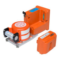
L3 FA5000 Maintenance Manual (209 pages)
COCKPIT VOICE RECORDER
Brand:
L3
| Category:
Voice Recorder
| Size: 2.26 MB
Table of Contents
Table of Contents
18
List of Figures (Continued)
27
List of Tables
31
General
33
Table 1. Shop Verification
38
Fa5000 Configurations
42
Figure 2. Model FA5000 Cockpit Voice Recorder Part Number Matrix
42
System Description
43
Figure 3. CVR Block Diagram
44
Figure 4. Recorder Data Flow Diagram
46
Software Module Description
47
CVR Task
47
Figure 5. CVR Task Flowchart
49
Datalink Task
50
Figure 6. Datalink Memory Format
52
OMS Task
53
Figure 7. Datalink Task Flowchart
53
Data Storage Task
54
Figure 8. OMS Task Flowchart
54
Figure 9. Data Storage Task Flowchart
56
BITE Task
57
Figure 10. BITE Task Data Flow Diagram
57
Figure 11. BITE Task Flowchart
59
GSE Task
60
Figure 12. GSE Task Data Flow Diagram
61
Figure 13. GSE Task Flowchart
62
Table 1 Model FA5000 CVR Audio Recording Specifications
63
Underwater Locator Beacon (ULB)
64
Circuit Boards
65
Power, Control and Monitor Signal Interface Characteristics
65
Figure 14. Model FA5000 CVR, (P/N: 500X-500X-( ))
66
Figure 15. Model FA5000 GACVR (P/N: 500X-500X-50)
67
Stop Recording Command
68
Control Unit Operating Power and Monitor Audio Signals
68
Control Unit Test and Bulk Erase Signals
69
Figure 16. Model FA5000 CVR, 120-Minute Audio Monitor Schemes
69
Output Audio Quality
70
Figure 17. Model FA5000 CVR 120-Minute Recording Schemes
70
Fa5000 Specifications
71
Applicable Documents
71
Physical Characteristics
72
Electrical Characteristics
72
Environmental Characteristics
72
Crash and Fire Protection
72
CSMU Torque Requirement
72
Installation
72
Figure 18. Interwiring Diagram, Recorder FA5000 CVR
74
Figure 19. Interwiring Diagram, Recorder FA500X GACVR
76
Theory of Operation
78
Model Fa5000 Cvr System Theory of Operation
78
Figure 20. FA5000 CVR Overall Function Block Diagram
78
Aircraft Interface (AI) PWA
79
Main Processor (MP) PWA
79
Software Considerations
80
Equipment Environment
80
Software Partitioning
80
Memory Requirements
80
On−Board Maintenance System (OMS) Interface
81
Fault Warning System (FWS) Interface
81
Table 2. Software Fault Warning Failures
81
Data Link (ATC) Interface
82
Push−To−Test (PTT) Functionality
82
Bulk Erase
82
Recorder Synchronization
83
Data Downloading
83
CVR RIPS Status Monitoring
84
RIPS Active
84
Table 3. CVR RIPS Pin Assignment
84
RIPS Fault
85
RIPS Maintenance
85
RIPS Present
85
Onboard Maintenance System Interface
86
Table 4. CVR OMS Output Words
86
Label 350 Status Word Output
87
Table 5. CVR Pins Assigned to RIPS Status Monitoring
87
Table 6. CVR Label 350 Output Format
87
Table 7. CVR Fault Reporting Interactions
88
Table 8. CVR Status Word Fault Reporting Criteria
89
Label 354 LRU Identification Output
90
Label 377 ARINC 429 Equipment Identification Word Output
92
OMS Input
93
DESCRIPTION and OPERATION − Cont
93
Cvr Datalink Input Interface
93
Data Link Input and Encapsulation
93
Figure 21. Generic Datalink Message Encapsulation Structure
95
Datalink Heartbeat
96
Williamsburg Bit−Oriented Protocol Version Support
96
Datalink Memory Capacity
97
Datalink Retrieval
97
Testing and Troubleshooting
99
General
99
Maintenance Philosophy
99
Model FA5000 CVR
99
Model Fa5000 Cvr Recorder In-Service Checkout
100
Recorder Interface Unit (Riu)
100
READ−OUT CENTER/7 (ROC/7) Interconnects
100
Table 101. 17TES0700
102
READOUT CENTER/7 (ROC/7) − Parts List
102
Figure 101. ROC/7 W/Cvr Automated Test Station Software (CATS) Model FA5000 TEST SETUP
103
READ−OUT CENTER/7 (ROC/7) − Sound Card Setup
104
Figure 102. CATS, Channels Control Screen
104
Figure 103. Volume Control
105
Figure 104. Sound Control, Recording
105
Figure 105. Line−In Properties, Line−In Level
106
Figure 106. Sound, Playback Devices
107
Figure 107. Speaker Properties, Levels
108
Figure 108. Volume Mixer, Speaker Levels
109
READ−OUT CENTER/7 (ROC/7) − CATS Autotest
110
ROC/7 − CATS Autotest Using DC Power
110
Figure 109. CATS, Connecting Pop-Up
111
Figure 110. CATS, Power Toggle
111
Figure 111. CATS, Start Test Toggle
112
Figure 112. CATS, Test Mode and Options Screen
112
Figure 113. CATS, CVDR Test Confirmation
113
Figure 114. CATS, CVDR Warning Message
113
Figure 115. CATS, Power Test Input
114
Figure 116. CATS, CVDR Instruction Window
114
Figure 117. CATS, CVDR Fault History Log
115
Figure 118. CATS, CVDR Clear Fault Log Confirmation
115
Figure 119. CATS, CVDR Fault History Log
116
Figure 120. CATS, Continue Test Confirmation
116
Figure 121. CATS, Test Results Screen
117
READ out CENTER/7 (ROC/7) − Autotest Descriptions
118
Power Test
118
Fault Log
118
Bulk Erase
119
Test Tone
119
Gmt 429
119
Rotor Speed
119
Channel Balance
120
Frequency Response
120
Signal to Noise and Distortion
121
Crosstalk Data
122
FSK Time
123
Audio out Monitor
123
Signal to no Signal
123
Shutdown
124
Capacitor
124
Data Link
124
Oms
125
Rips
125
Fred
125
Fdr
125
Read−Out Center/7 (Roc/7) − Audio Download & Playback
126
Test the Underwater Locator Beacon (Ulb)
127
Aircraft Interface
128
Table 102. Aircraft Interface Troubleshooting Chart
128
Main Processor
137
Table 103. Main Processor Troubleshooting Chart
137
Crash-Survivable Memory Unit (Csmu)
147
Table 104. CSMU Troubleshooting Chart
147
Disassembly
149
General
149
Recorder Independent Power Supply (Rips) Module
149
Remove RIPS Module
149
Condition RIPS Module after Expired Shelf Life (One Year in Storage)
150
Figure 301. RIPS Module and FA5000 Connector Covers
150
Storage Instructions
151
Storage of the RIPS Module in Original Container
151
Storage of RIPS Without Original Container
151
(See Figure 302 or IPL Figure 1, Item 120)
152
(See IPL Figure 1, Item 150)
152
Model Fa5000 Disassembly Instructions
152
(See Figure 304 or IPL Figure 1, Item 10)
154
Figure 302. CSMU Memory Assembly Removal Diagram
154
(See Figure 304 or IPL Figure 1, Item 25)
155
Figure 303. Rear Cover Removal Diagram
155
Figure 304. Aircraft Interface (AI) PWA Removal Diagram
156
Cleaning
157
Cleaning Procedures
157
General
157
Materials Required
157
Table 401. Cleaning Materials Required
157
Printed Wiring Assembly Cleaning
158
Connector Cleaning
158
Underwater Locator Beacon Cleaning
158
Figure 401. Underwater Locator Beacon
159
Checks
161
Main Recorder Assembly
161
Mechanical Inspection
161
Electrical Inspection
162
Underwater Locator Beacon (ULB)
162
Repair
163
General
161
General
163
Assembly
165
Assembly Instructions
165
General
165
Required Materials
165
Table 701. Required Assembly Materials
165
General Assembly Techniques
166
(See Figure 701 or IPL Figure 1, Item 105)
166
(See 703 or IPL Figure 1, Item 10)
167
Figure 701. Aircraft Interface PWA Installation Diagram
167
(See Figure 703 or IPL Figure 1, Item 185)
168
Figure 702. Rear Cover Installation Diagram
168
Figure 703. Crash Survivable Memory Unit (CSMU) Assembly
169
(See IPL Figure 1, Item 150)
170
Recorder Independent Power Supply (Rips) Module
170
RIPS Shelf Life
170
RIPS Module Connector Cover
170
RIPS Module Connector Cap
170
Install RIPS Module
171
Figure 704. FA5000 Connector Cover and RIPS Connector Cap
171
Condition RIPS Module after Expired Shelf Life (One Year in Storage)
173
Figure 705. Install RIPS Module
173
Storage Instructions
174
Storage in Original Container
174
Storage Without Original Container
174
Place an Order
175
Product Support
175
Return Equipment to Authorized Repair Facility
176
Shipping Considerations
177
Return Equipment from Outside the United States − Import Compliance
177
Payment Information
178
Fits and Clearances
179
General
179
Physical Characteristics
179
Electrical Characteristics
180
RIPS Power Logic
180
Crash- and Fire-Survival Characteristics
181
Environmental Characteristics
181
Torque Requirements
181
Table 801. Model FA5000 Environmental Characteristics
182
Special Tools, Fixtures and Equipment
185
System Specifications
179
General
185
Table 901. 17TES0700 READOUT CENTER/7
185
Ground Support Equipment (Gse) Descriptions
187
Audio Data Link Player Software
188
Hardware Requirements for Audio & Data Link Player Software
188
Hardware Requirements for Downloading CVR Data
188
Advertisement
L3 FA5000 Component Maintenance Manual With Illustrated Parts List (202 pages)
COCKPIT VOICE and DATA RECORDER
Brand:
L3
| Category:
Voice Recorder
| Size: 1.71 MB
Table of Contents
Table of Contents
22
List of Figures
29
List of Tables
33
Table 1. Shop Verification
40
Figure 2. Model FA5000 Cockpit Voice Recorder Part Number Matrix
44
Figure 3. CVDR Block Diagram
47
Table 1. Cockpit Area Microphone Pre-Amplifier Input Attenuation Decode
49
Table 2. Processor Board PWA to Aircraft Interface PWA, P1
49
Table 3. Hold up Capacitor Voltage to CPU PWA, J6
57
Table 4. Hold up Capacitor Voltage Return to CPU PWA, J7
57
Table 5. Aircraft Interface PWA to Video Board PWA, J4
59
Physical Characteristics
59
Electrical Characteristics
59
Environmental Characteristics
59
Crash and Fire Protection
59
CSMU Torque Requirement
59
Installation
59
Table 6. P/N: 5001−61XX−11 Pin Outs and Signal Descriptions
59
Cvr Testing and Troubleshooting
67
General
67
Maintenance Philosophy
67
Model FA5000CVDR
67
Model Fa5000Cvdr Recorder In-Service Checkout
68
Recorder Interface Unit (Riu)
68
READ−OUT CENTER/7 (ROC/7) Interconnects
68
Table 101. 17TES0700 READOUT CENTER/7 (ROC/7)
70
Figure 101. ROC/7 W/Cvdr Automated Test Station Software (CATS)
71
Model FA5000CVDR TEST SETUP
71
READ−OUT CENTER/7 (ROC/7) − Sound Card Setup
72
Figure 102. CATS, Channels Control Screen
72
Figure 103. Volume Control
73
Figure 104. Sound Control, Recording
73
Figure 105. Line−In Properties, Line−In Level
74
Figure 106. Sound, Playback Devices
75
Figure 107. Speaker Properties, Levels
76
Figure 108. Volume Mixer, Speaker Levels
77
READ−OUT CENTER/7 (ROC/7) − CATS Autotest
78
ROC/7 − CATS Autotest Using DC Power
78
Figure 109. CATS, Connecting Pop-Up
79
Figure 110. CATS, Power Toggle
79
Figure 111. CATS, Start Test Toggle
80
Figure 112. CATS, Test Mode and Options Screen
80
Figure 113. CATS, CVDR Test Confirmation
81
Figure 114. CATS, CVDR Warning Message
81
Figure 115. CATS, Power Test Input
82
Figure 116. CATS, CVDR Instruction Window
82
Figure 117. CATS, CVDR Fault History Log
83
Figure 118. CATS, CVDR Clear Fault Log Confirmation
83
Figure 119. CATS, CVDR Fault History Log
84
Figure 120. CATS, Continue Test Confirmation
84
Figure 121. CATS, Test Results Screen
85
READ out CENTER/7 (ROC/7) − Autotest Descriptions
86
Fault Log
86
Power Test
86
Bulk Erase
87
Gmt 429
87
Rotor Speed
87
Test Tone
87
Channel Balance
88
Frequency Response
88
Signal to Noise and Distortion
89
Crosstalk Data
90
Audio out Monitor
91
FSK Time
91
Signal to no Signal
91
Capacitor
92
Data Link
92
Shutdown
92
Fdr
93
Fred
93
Oms
93
Rips
93
Read−Out Center/7 (Roc/7) − Audio Download & Playback
94
Table 102. Underwater Locator Beacon Test Using L−3AR Test Set P/N: 17TES0015
95
Fdr Function Testing and Fault Isolation
97
General
97
Recommended Test Equipment
97
Test Conditions
97
Table 201. Recommended Test Equipment
97
Recorder Test States
98
FA5000CVDR Operating Mode States
98
Fa5000Cvdr Bench Test Procedures
100
Initial Test Setup (Refer to Figure 201)
100
Figure 201. ROSE/RI Setup for Testing FA5000CVDR Recorders
101
Fault Condition Reset
102
Power Check
102
FA5000CVDR Recorder Initialization Check
103
Figure 202. RI Recorder Status Window Indications
103
Loss of Input Data or Synchronization BIT Check
105
Table 202. FA5000CVDR Status Entry: Checksum Value
105
FA5000 Autotest & Return to Service Check
106
Figure 203. Recorder Automatic Test Information Pop−Up Screen
108
Figure 204. RI Recorder Status Autotest Indication
109
Set Final Memory Marker
109
Table 203. Underwater Locator Beacon Test Using L−3AR Test Set P/N: 17TES0015
111
Table 204. Aircraft Interface Troubleshooting Chart
112
Table 205. Main Processor Troubleshooting Chart
119
Table 206. CSMU Troubleshooting Chart
130
Disassembly
133
General
133
Model 500 Recorder Independent Power Supply (Rips) Removal Instructions
133
Model Fa5000 Disassembly Instructions
134
Figure 301. Recorder Independent Power Supply (RIPS) Removal
134
(See Figure 4 or IPL Figure 1, Item 155A/B)
135
Crash-Survivable Memory Unit (CSMU) Removal (See Figure 302 or IPL Figure 1, Item 120)
137
Figure 302. Remove Underwater Locator Beacon from Cockpit Voice and Data Recorder P/N: 5001-6103-( ), 5011-6103-( ), 5001-6133-( ), 5003-6103-( )
137
Figure 303. CSMU Memory Assembly Removal Diagram
139
Rear Cover Removal (See Figure 304 or IPL Figure 1, Item 10)
141
Aircraft Interface (AI) PWA Removal (See Figure 304 or IPL Figure 1, Item 30)
141
Figure 304. Rear Cover Removal Diagram
141
Main Processor (MP) PWA Removal (See Figure 305 or IPL Figure 1, Item 50)
142
Figure 305. Aircraft Interface (AI) PWA Removal Diagram
142
Figure 306. Main Processor (MP) PWA Removal Diagram
144
(See 306 or IPL Figure 1, Item 175)
145
Figure 307. Main Processor (MP) PWA Removal Diagram
145
General
147
Table 401. Cleaning Materials Required
147
Figure 401. Underwater Locator Beacon
149
Required Materials
155
Table 701. Required Assembly Materials
155
(See 701 or IPL Figure 1, Item 175)
156
Assembly Instructions
156
General Assembly Techniques
156
(See Figure 702 or IPL Figure 1, Item 50)
157
Figure 701. Video Card Installation Diagram
157
(See Figure 703 or IPL Figure 1, Item 30)
159
Figure 702. Main Processor (MP) Installation Diagram
159
Figure 703. Aircraft Interface PWA Installation Diagram
160
(See 704 or IPL Figure 1, Item 10)
161
(See Figure 705 or IPL Figure 1, Item 120)
162
Figure 704. Rear Cover Installation Diagram
162
Figure 705. Crash Survivable Memory Unit (CSMU) Assembly
164
(See Figure 706 and IPL Figure 1, Item 155A/B)
165
Figure 706. Underwater Locator Beacon Assembly
166
Model 500 Recorder Independent Power Supply (Rips) Installation Instructions
167
Figure 707. Recorder Independent Power Supply (RIPS) Installation
168
Storage in Original Containers
168
Storage Instructions
168
Shipment Container Kit
169
Storage Without Original Containers
169
Fits and Clearances
171
General
171
Physical Characteristics
171
System Specifications
171
Table 801. Model FA5000 Environmental Characteristics
174
Figure 1. Model FA5000 Cockpit Voice Recorder/Flight Data Recorder
177
Figure 801. Sheet 1 of 2
177
Model FA5000 Cockpit Voice Recorder/Flight Data Recorder
177
Outline & Dimension Drawing
177
Figure 801. Sheet 2 of 2
178
Model FA5000 Cockpit Voice Recorder/Flight Data Recorder
178
Outline & Dimension Drawing
178
Table 901. 17TES0700 READOUT CENTER/7 (ROC/7)
180
Advertisement
Related Products
L3 FA2100 CVR
L3 2100-1010-00
L3 2100-1010-50
L3 2100-1010-51
L3 2100-1020-00
L3 2100-1020-02
L3 2100-1020-50
L3 2100-1020-51
L3 2100-1025-02
L3 2100-1025-12
L3 Categories
Measuring Instruments
Voice Recorder
Control Panel
Accessories
Antenna
More L3 Manuals
Login
Sign In
OR
Sign in with Facebook
Sign in with Google
Upload manual
Upload from disk
Upload from URL