Table of Contents
Advertisement
Quick Links
Advertisement
Table of Contents

Related Manuals for Paravan PR Biolution


Summary of Contents for Paravan PR Biolution
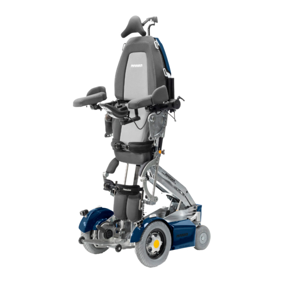
- Page 1 The Paravan wheelchair series User manual PR Biolution www.paravan.com V2.1...
- Page 2 Valid for the following models: Paravan PR Biolution (Stand-Up Wheelchair) Publisher and copyright: PARAVAN GmbH Date of issue: 1.1.2017 Document number: Biolution Benutzerhandbuch V2.1_EN...
- Page 3 Dear Customer, We would like to thank you for choosing our PARAVAN standing wheelchair. In these operating instructions you will receive all the important information and instructions regarding your new Biolution. We would like to ask you to carefully read the following to ensure that your Biolution will continue to work without problems for many years to come.
-
Page 4: Table Of Contents
Contents General Company details ....................13 Your manufacturer ........................13 1.1.1 Copyright ..........................14 1.1.2 Technical nature of documentation ..................14 Regarding these operating instructions ...............15 Liability exclusion ........................16 2.1.1 Guarantee ..........................17 2.1.2 Technical modifications ......................18 Target group ..........................20 Explanation of symbols ...................... - Page 5 Information Product-specific information ................35 Trademark and type designation (type plate) ............... 35 Location of the type designation (type plate) ................ 36 Information on your Biolution ....................37 5.3.1 The type plate of your Biolution ....................37 Accessories ..........................38 5.4.1 Supplied accessories....................... 38 5.4.2 Deliverable accessories ......................
- Page 6 Settings on the Biolution, electronic ..............48 Settings on the Biolution, mechanical ..............49 10.1 Receiving your new Biolution ....................49 10.2 The armrest pad ........................50 10.2.1 Set the angle of the armrest pad.................... 50 10.2.2 Set the horizontal position of the armrest pad ..............51 10.3 Armrest .............................
- Page 7 11.10.1 Fording ability, driving through water ..................73 11.10.2 Climbing / traversing ability ....................74 11.10.3 Load bearing capacity ......................74 11.10.4 Rough ground or terrain ......................74 11.10.5 Slippery ground, traction ......................74 Parking and storing the Biolution .................75 12.1 Control panel R-NET CJSM2 ....................
- Page 8 Help Moving from the Biolution's seat ................91 15.1 Procedure when moving sideways from the seat..............92 Maintenance and servicing .................. 93 16.1 Service partner ......................... 93 16.2 Cleaning and care ........................94 Disposal and environmental protection ..............95 17.1 Packaging material ........................96 17.2 Recommissioning ........................
- Page 9 19.8.1 Procedure when charging the Biolution ................. 109 19.8.2 The charger ..........................110 19.8.3 Installing the charger, installation site ..................110 Technical equipment ...................111 20.1 Technical data and measurements ..................111 20.2 Spare parts ..........................116 Fault elimination....................118 21.1 Flash code of the status display of the control panel ............118 Electromagnetic compatibility (EMC) ..............120 22.1 Information regarding electromagnetic compatibility ............
- Page 10 Table of illustrations Fig. 1: QR code ............................ 13 Fig. 2: Travel direction ......................... 15 Fig. 3: Safety instruction ........................22 Fig. 4: Type plate ..........................35 Fig. 5: Location of type plate ......................36 Fig. 6: Docking station ........................38 Fig.
- Page 11 Fig. 30: Spring plunger latch locked ..................... 62 Fig. 31: Decoupling biometric joints ....................63 Fig. 33: Inserting the quick-release pin ....................63 Fig. 32: Folding up the joint ........................63 Fig. 34: Brake lock release lever (emergency release) ............... 65 Fig.
-
Page 12: Table Of Illustrations
Fig. 60: Setting the display brightness ....................89 Fig. 59: Autom. display brightness ...................... 89 Fig. 62: Turn signal right / left ......................90 Fig. 61: Lock symbol ..........................90 Fig. 63: Move from the seat, footrests ....................92 Fig. 64: Move from the seat, armrest .................... -
Page 13: Company Details
Company details Your manufacturer PARAVAN GmbH Registered office / headquarters / production Paravanstraße 5-10, D-72539 Pfronstetten-Aichelau › Phone: +49 (0) 73 88 / 99 95-91 › Fax: +49 (0) 73 88 / 99 95-999 › Email: info@paravan.com Fig. 1: QR code › Internet: www.paravan.com › Managing Director: Mr. Roland Arnold Many mobile telephones and PDAs have built-in cameras and... -
Page 14: Copyright
Germany of 9th September 1965 in its respective up-to-date version. It is generally subject to remuneration. Contraventions are subject to the penal provisions of the Copyright Act. › Copyright © PARAVAN GmbH 2017. All rights reserved! 1.1.2 Technical nature of documentation All details on technical data / specifications, illustrations and information in these operating instructions comply with the status of the editorial deadline in July 2014. -
Page 15: Regarding These Operating Instructions
Regarding these operating instructions These operating instructions do not constitute a maintenance and repair manual and therefore are not suitable to use for the private carrying out of maintenance and repair work, or to provide instruction on this. You will receive information on the type of design and operation throughout the complete transport life cycle (delivery) to the decommissioning (shutdown) of the Biolution. The most significant product features are listed and described in the following. All the specified product features... -
Page 16: Liability Exclusion
The operation of the Biolution without faults or malfunctions can only be guaranteed if the knowledge gained from these operating instructions is observed and implemented. PARAVAN GmbH does not accept any liability or guarantee for damage or malfunctions which result during operation due to the non-observance of these operating instructions or due to modifications made to the Biolution. -
Page 17: Guarantee
2.1.1 Guarantee Guarantee services are based entirely on the respective PARAVAN guarantee provisions. Excluded from guarantee claims is damage which has occurred due to: › Wear › Improper operation or use, e.g. overloading › Incorrect/infrequent maintenance › Incorrect/infrequent care See your personal “guarantee card”. -
Page 18: Technical Modifications
2.1.2 Technical modifications All modifications to safety installations and technical modifications to the Biolution, even if minor, are strictly prohibited! All modifications must be authorised or carried out by PARAVAN GmbH. PARAVAN GmbH reserves the right to undertake technical modifications and improvements to the product in the interest of our customers and progressive development. Claims relating to the guarantee and warranty shall expire in the case of all modifications made to the Biolution not authorised by PARAVAN GmbH. Furthermore, dangerous malfunctions cannot be ruled out! Regarding these operating instructions... - Page 19 WA R N I N G Danger of injury for persons when operating a Biolution which does not correspond to the original or delivered condition. Material damage to the Biolution by the use of non-authorised parts or incorrectly installed parts. ›...
-
Page 20: Target Group
Target group The operator must acquire or gain a level of knowledge relating to the following points before operating the Biolution: › Knowledge of the content of the operating instructions in order to safely operate and also be able to move the Biolution. -
Page 21: Explanation Of Symbols
Explanation of symbols When reading the operating instructions you will encounter the following symbols and warning symbols. The “Caution Danger!” logo indicates danger points. The counteraction measures specified in the respective text must be followed in all cases. This symbol is always used in combination with the respective signal word which reflects the level of danger: › Danger! - Direct danger to life and limb (irreversible). › Warning - potential danger to life and limb (irreversible). ›... -
Page 22: Structure Of Safety Information
2.3.1 Structure of safety information The security information provides the following information: › Warning or hazard symbol . › Type and source of danger . › Signal word . › Consequences upon the occurrence of danger . ›... -
Page 23: Safety Instructions
Safety instructions Generally valid safety instructions 3.1.1 Operation instructions For your protection and for the protection of people in your vicinity and of the environment, the following safety instructions must be observed and followed at all times. D A N G E R! Danger of crushing from touching moving parts e.g. - Page 24 WA R N I N G Danger of tipping for persons when operating a Biolution when travelling at an incline of more than 10°. Danger of tipping for persons when operating a Biolution when travelling downhill and if the sitting position is in the front position.
- Page 25 WA R N I N G Danger of injury for persons when operating a Biolution which does not correspond to the original or delivered condition. Material damage to the Biolution by the use of non-authorised parts or incorrectly installed parts. ›...
- Page 26 WA R N I N G Danger of Injury for persons while travelling with a Biolution on rough ground. Danger of falling and tipping for persons while operating the Biolution on grounds with diminished load bearing capacity. Material damage to the Biolution from mechanical and physical influences while travelling on rough terrain.
-
Page 27: Information Regarding Use
3.1.2 Information regarding use C A U T I O N Material damage to the Biolution from overloading the vehicle. Material damage to the Biolution from the effect of high temperatures above 41°C. Material damage to the Biolution from overcharging of the batteries when travelling downhill. -
Page 28: Information Regarding Transport
3.1.3 Information regarding transport C A U T I O N Material damage to the Biolution by it slipping from the ramp or from the lift while loading. Material damage to the Biolution by improper securing or transport in the Biolution transporter. ›... -
Page 29: Performance Description
Performance description Manufacturing standard The PARAVAN Biolution is a multifunctional power wheelchair which is highly suitable for indoor and outdoor use due to its compactness and mobility. The Biolution is designed and tested so that the largest possible level of safety is provided for the operator and their environment. -
Page 30: Correct Use
Correct use The PARAVAN Biolution's function and design are intended to transport a person indoors and outdoors. The control panel including joystick or optional operating units in the case of/for special operation is the interface relating to user operation and the liability of the manufacturer for the Biolution. -
Page 31: Usability Of The Biolution
4.2.1 Usability of the Biolution - unproblematic › Transport of a person with a maximum body weight of 150kg. › Use as driver's or co-driver's seat depending on equipment. › Use within the German road traffic regulations (“StVO”), assuming complete and intact lighting. See section “12 Driving with the Biolution” - problematic or prohibited ›... -
Page 32: Declaration Of No Objection Dangerous Goods (Storage Battery)
4.2.2 Declaration of no objection dangerous goods (storage battery) PARAVAN GmbH uses storage batteries which are classified as “non-dangerous goods”, as long as these storage batteries are not mechanically damaged in any way. The maintenance-free non-woven lattice storage batteries and the maintenance-free lead gel storage battery are leakproof and non-hazardous for all methods of transport in accordance with: ›... -
Page 33: German Regulations On Assistive Technology (Hilfsmittelverordnung, Hmv No.)
4.2.3 German regulations on assistive technology (Hilfsmittelverordnung, HMV no.) The Biolution standing wheelchairs are approved in accordance with the assistive technology guidelines: › Kassenarztrecht in Nordwürttemberg – Richtlinien und Normen und Verordnungen und Leistungen (Panel doctors law in Northern Württemberg - guidelines and standards and regulations and services), page B 2 - 1 ff As auxiliary equipment permitted under the German regulations on assistive technology number: ›... -
Page 34: Indication
4.2.5 Indication The inability to walk or severely limited ability to walk within the context of the basic need to move in your own home. The provision of wheelchairs with a standing feature is advisable if regular (several times per day) standing training must be carried out as a therapeutic action, and other standing aids, e.g. -
Page 35: Product-Specific Information
Product-specific information Trademark and type designation (type plate) This information can be found on the type plate. It is very important to provide this in any correspondence with PARAVAN GmbH so that you receive relevant professional advice. › Model name ... -
Page 36: Location Of The Type Designation (Type Plate)
Location of the type designation (type plate) The type designation (type plate) is affixed to the Biolution in a 1-fold design. The type designation (type plate) has dimensions of approx. 70mm x 40mm. › The type designation (type plate) is situated at the bottom on the right of the battery box of the Biolution. Fig. -
Page 37: Information On Your Biolution
Information on your Biolution Please ensure that this information is recorded upon the supply of the Biolution, or if necessary enter the information yourself, so that you always have it to hand. › Day of delivery/supply › Supply by (dealer or branch) 5.3.1 The type plate of your Biolution Stick a duplicate of your type plate here! -
Page 38: Accessories
› Allen key, size 5. 5.4.2 Deliverable accessories › PARAVAN docking station to quickly and easily fasten the Biolution in a vehicle, e.g. if the power wheelchair is going to be used as a driver's seat. Fig. 6: Docking station... -
Page 39: Description/Function Of The Biolution
Description/function of the Biolution The special orthopaedic seat The special orthopaedic seat is an in-house development by PARAVAN GmbH that has been tailored to the precise needs of its customers. It is equipped with: › Special shock absorbers in the seat to provide relief to the thigh muscles. -
Page 40: Joystick Control
Joystick control All the functions of the Biolution can be selected or accessed via the joystick, the control panel and the integrated control system, such as e.g.: › Steering of the Biolution, › Braking behaviour of the Biolution, › Speed, control of the two drive motors, ›... -
Page 41: Lift And Tilt (Seat Inclination)
Lift and tilt (seat inclination) The Biolution is equipped with a stable one arm lift which can reach an extended height of up to 80 cm. This ensures a maximum activity radius in everyday domestic life and in the work environment. The raising process can be interrupted and fixed in any direction of movement and at any position. -
Page 42: Road-Safe In Accordance With The Road Traffic Licensing Act (Stvzo)
Road-safe in accordance with The Road Traffic Licensing Act (StVZO) The Biolution can be optionally upgraded so that it becomes a vehicle permitted in traffic with: › LED headlights for optimum illumination . › LED direction indicator . › LED rear lights for the best possible visibility . ›... -
Page 43: Overview Of The Biolution
Overview of the Biolution Definition of parts and their location The following terms for parts or individual parts are used in the operating instructions. Their location on the Biolution is shown in the illustration. › Control panel with joystick ›... -
Page 44: Definition Of Parts And Their Installation Position, Chassis
Definition of parts and their installation position, chassis The following terms for parts or individual parts are used in the operating instructions. The installation position on the chassis of the Biolution is shown in the diagram. › Seat plate ›... -
Page 45: Fig. 11: Parts, Chassis Front
› Drive wheel › Rigging eye › Control units › Preparation of docking station › Brake lock release lever, emergency release › Drive motor › Lifting motor with lifting rod and gear mechanism ›... -
Page 46: Supply Of Biolution
Check your Biolution for completeness and compare the items received with the delivery with your order documents. If anything is unclear, contact PARAVAN GmbH immediately! Check (visually inspect) that the Biolution is in proper condition. Report damage which can be attributed to delivery or transport immediately in writing to your ›... -
Page 47: Tools Supplied
Tools supplied You will receive the following tools when the Biolution is delivered: › Socket wrench with T-handle, SW 13. Fig. 12: Socket wrench › Allen key, size 5. Fig. 13: Allen key Supply of Biolution... -
Page 48: Settings On The Biolution, Electronic
Settings on the Biolution, electronic The setting and configuration of the PARAVAN control unit is very complex and, for your own safety, can only be undertaken by your service technician. All parameters of the PARAVAN control unit can be subsequently set to your requirements and desires. These include: › All driving features such as e.g. moving off and braking. -
Page 49: Settings On The Biolution, Mechanical
All mechanical parts or equipment and control elements are set to your body dimensions. If adjustment is still needed however, this can be undertaken at any time. Your PARAVAN Biolution is designed in such a way that it can be adjusted to the body dimensions in all requirements. -
Page 50: The Armrest Pad
10.2 The armrest pad The angle of the armrest pad can be tilted. It can also be adjusted horizontally, and positioned further forwards or backwards, allowing it to be adapted for any purpose and every body size. 10.2.1 Set the angle of the armrest pad. These instructions apply to both the right and left sides. -
Page 51: Set The Horizontal Position Of The Armrest Pad
10.2.2 Set the horizontal position of the armrest pad These instructions apply to both the right and left sides. Proceed as follows to check and set the position of the armrest pad: › Loosen the wing bolt. › Push the armrest pad ... -
Page 52: Armrest
10.3 Armrest The armrest is multi-horizontal in all directions (projection) and can be vertically adjusted or adjusted at an angle, and thus can be adapted to every body measurement. Changing the position of the armrest potentially involves using another setting! Proceed as follows to check and set the position of the armrest: ›... -
Page 53: Set The Height Of The Armrest
10.4 Set the height of the armrest These instructions apply to both the right and left sides. The clamping screw is a tappet spanner in its function and design! This involves the following function: › Clamping screw loose -> armrest is locked or fixed. › Clamping screw fixed-> armrest is loose or movable. Proceed as follows to check and set the height of the armrest: Fig. -
Page 54: Fig. 18: Lever, Clamping Screw
After changing the position of the armrest, the lever of the clamping screw must be reset if necessary so that no danger can result from this (injury of passers-by or the pulling off of the lever). › Lift lever. ›... -
Page 55: Set The Angle Of The Armrest
10.5 Set the angle of the armrest The armrest is pivoted on the attachment point. This allows the complete armrest to be swung upwards for comfortable sitting and standing or moving from the wheelchair's seat. These instructions apply to both the right and left sides. The following setting options are available: ›... -
Page 56: Set The Projection Of The Armrest
10.6 Set the projection of the armrest This work instruction applies to the right and left sides, if necessary the rotational direction of the screw connection is laterally reversed! Proceed as follows to check and set the projection of the armrest: ... -
Page 57: Setting The Mobility Of The Control Panel
10.7 Setting the mobility of the control panel The horizontal swivel mechanism of the control panel can be set in relation to the degree of hardness (response behaviour or the mobility of the joints). This level of stiffness can only be set by your service technician! See section “8.3 Tools supplied”... -
Page 58: Footrest Unit
10.8.1 Setting the lower leg length The support of the lower leg or the lower leg length can be electrically set via the PARAVAN control unit in the length adjustment setting. Fig. 22: Lower leg length › Manually adjustable... -
Page 59: Setting The Tibial Angle
10.8.2 Setting the tibial angle The support of the lower leg or the tibial angle (between upper and lower leg) can be electrically modified via the PARAVAN control unit in the angle adjustment setting, depending on the equipment version. › Select menu in the control unit. › Select the settings. See section “15 Control”... -
Page 60: Mechanically Folding Biometric Knee Joints
10.9 Mechanically folding biometric knee joints › Completely retract the foot support until the screw head can be seen in the middle of the hole. Under heavier loads, manual intervention may be required to reach the end position. Fig. 24: Biometric foot angle ›... -
Page 61: Fig. 26: Spring Plunger Latch Locked
› Pull out the inner spring plunger latch ① and twist gently to lock. ① Fig. 26: Spring plunger latch locked Fig. 27: Spring plunger latch unlocked › The joint is now released and can be folded up. Fig. 28: Folded joint Settings on the Biolution, mechanical... -
Page 62: Fig. 29: Spring Plunger Latch Unlocked
› Swing the joint back into its star- ① ting position and push the black ① latch ① back into place. Fig. 29: Spring plunger latch unlocked Fig. 30: Spring plunger latch locked Settings on the Biolution, mechanical... -
Page 63: Fig. 31: Decoupling Biometric Joints
› Remove the quick-release pin ① and make sure that both joint lo- cking pins ① also slide back into the joint smoothly. If they do not, the joint must be pushed back manually to make sure the pins lock into place. Fig. -
Page 64: Driving With The Biolution
11. Driving with the Biolution 11.1 Insurance, liability insurance We recommend that you speak with your insurance advisor before starting to use the Biolution so that its use is included in your insurance - in particular in your liability insurance. Please note that a legal requirement may exist to insure the Biolution during use in road traffic within the context of the respective legal provisions. -
Page 65: Function Check Before The Trip
11.2 Function check before the trip Before commencing each trip, the following points must be checked for your own safety: It might be necessary to draw on the expertise of a second person for the check. › Function check of the brakes. The brake lock release lever ... -
Page 66: Controlling The Biolution, Directions Of Travel
11.3 Controlling the Biolution, directions of travel The Biolution is controlled via the joystick on the control panel. The following basic control options are available if you put the joystick into the position below: › Joystick forwards -> The Biolution travels forwards. ›... -
Page 67: Navigating Bends, Turning Corners
11.4 Navigating bends, turning corners The PARAVAN Biolution is equipped with front-wheel drive. This means that the rear swings out during steering motions i.e. turning corners. This is how you navigate a bend: › Push the joystick into the required travelling position (forwards or backwards). -
Page 68: Braking With The Biolution
11.5 Braking with the Biolution 11.5.1 Braking systems on the Biolution Two independently working braking systems (safety systems) are used in the PARAVAN Biolution in order to guarantee the greatest possible level of safety. The Biolution has a parking and service brake which complies with the Road Traffic Licensing Act (StVZO.) The functions of the individual safety systems are as follows:... -
Page 69: Braking The Biolution
11.6 Braking the Biolution The braking distance i.e. the distance from initiating the braking process until the Biolution comes to a standstill is heavily dependent on factors such as: › Ground or condition of the road. › Total weight (vehicle and driver) of the Biolution. When braking from full speed at approx. -
Page 70: Travelling On Hills, Up And Downhill Travel
11.7 Travelling on hills, up and downhill travel You must observe the following information for your own safety when travelling up and downhill: › Put the longitudinal seat adjustment mechanism into the furthest back position in order to avoid slipping. ›... -
Page 71: The Movement Programs / Movement Levels
11.8 The movement programs / movement levels The PARAVAN Biolution has five different movement programs or levels. You can select the desired movement level or final speed of the Biolution on the control panel. The maximum final speed in the respective movement level is reached by moving the joystick as far as it will The functions of the individual movement levels are as follows: › Movement level 1 Highest control of the Biolution 20% of the final speed, driving indoors. › Movement level 2 40% of the final speed. › Movement level 3 60% of the final speed. -
Page 72: Manual Driving, Push Mode
11.9 Manual driving, push mode 11.9.1 Operation of the brake lock release lever (emergency release) › If you want to push the Biolution you must set both brake lock release levers on the left and right drive side to “UNLOCK” (downwards). A push handle can be optionally installed on the backrest. -
Page 73: Requirement For Roads, Grounds
11.10 Requirement for roads, grounds WA R N I N G Danger of tipping for persons when operating a Biolution when travelling at an incline of more than 10°. Danger of tipping for persons when operating a Biolution when travelling downhill and if the sitting position is in the front position. -
Page 74: Climbing / Traversing Ability
11.10.2 Climbing / traversing ability › While travelling over obstacles that are higher than approx. 60-70mm, you could touch the ground and get stuck or tip over with your Biolution with the battery box. 11.10.3 Load bearing capacity › Do not travel across grounds on which there is a danger that you could fall and therefore could become stuck or tip over. -
Page 75: Parking And Storing The Biolution
12. Parking and storing the Biolution In order to avoid damage to the Biolution you must observe the following rules if you park the Biolution e.g. overnight, or do not use it for an extended time period: › Create a connection to the charging device. ›... -
Page 76: Control Panel R-Net Cjsm2
12.1 Control panel R-NET CJSM2 › Press and hold the “On” key for at least 3 seconds -> the lock symbol will appear. -> Immobiliser is active. ① ② › Press and hold the “On” key -> the lock symbol will appear. ›... -
Page 77: Loading And Transport Of The Biolution
13. Loading and transport of the Biolution The Biolution must always be shut down and correctly secured or fastened in the vehicle during transport. For loading the Biolution, loading aids like: › ramps, lifts and hoists with sufficient load-bearing capacity must be used. 13.1 Rules for loading wheelchairs The following rules must be observed for and during loading: ›... -
Page 78: Securing Of The Biolution, Fastening
At the front, two rigging eyes › At the rear, one rigging eye If your vehicle is equipped with a PARAVAN docking station, further fastening is not necessary. See section “5.4.2. Deliverable accessories” Fig. 40: Attachment point at the rear... -
Page 79: Controls
14. Controls 14.1 Control panel R-NET CJSM2 14.1.1 Overview of the control elements With the control panel (joystick) built into your power wheelchair, you ⑫ can control all of the power wheelchair's driving, steering and braking ③ processes. All additional functions which are equipped with displace- ⑩... -
Page 80: Status Display
14.1.2 Status display The function keys are used to select the specific functions displayed in the assigned fields on the display. Symbols of the status indicator: Charging status of the storage batteries ① › › Direction indicator, left ② “On/off” light ③ › › System status ④ (“tortoise” → speed control active) › Direction indicator, right ⑤ Fig. -
Page 81: Start, Switch Off
14.1.3 Start, switch off Start Push the “on/off” switch ① upwards. › The status display briefly flashes and the last selected function in terms of movement level/seat function is shown. › Press the switch ① downwards again to: - Select movement levels 1 to 5. - Then switch to the seat functions. -
Page 82: Switch Direction Indicator On And Off
14.1.4 Switch direction indicator on and off Press key ① or ② for the respective direction indicator, left or right. › The selected direction indicator will flash. › Press once more → direction indicator switches off. Fig. 48: Turn signal right / left 14.1.5 Switch light on and off Press the key ... -
Page 83: Switch Hazard Lights On And Off
14.1.6 Switch hazard lights on and off Press the “hazard lights” key for the “hazard lights on” function. › The hazard lights switch themselves on, while the hazard lights symbol flashes red and both direction of travel symbols flash green. Press the key again → the hazard lights/hazard lights symbol switch themselves off. › Fig. 50: Hazard lights on / off Fig. -
Page 84: Driving Functions Overview
14.1.7 Driving functions overview Overview of the driving functions shown on the display of the control pa- nel during driving, steering and braking actions of the power wheelchair. ⑤ ② Selected drive program/movement level ① › ⑥ ① › Respective setting (having drilled down) for the selected movement level (1 to 5)Maximum speed in the selected drive program ②... -
Page 85: Select Drive Program, Drive
14.1.8 Select drive program, drive The power wheelchair must be in driving mode. › The last selected drive program is shown on the display (profiles 1 to 5). Drive profiles 1 to 5 are further divided into 5 levels once you drill down. ① Press the switch upwards ① or downwards ② to switch to a higher or ② lower sub-level. › The selected drive program and sub-level will appear on the display. Fig. -
Page 86: Electrical Seat Adjustment
14.1.9 Electrical seat adjustment Use the MODE key to switch from the drive program to the seat func- tions. Select the desired seat function by moving the joystick “← left/right →”. › The adjustment functions menu will appear on the display. Only the released or available functions can be selected. -
Page 87: Set Time/Date
14.1.10 Set time/date Press and hold the “hazard lights” key to access the “Settings” menu. › The special functions menu will appear on the display. Move the joystick → left/right to access the options “year, month, date, day of the week, hours and minutes”. Select the desired option by mo- ving the joystick “←... -
Page 88: Show/Hide Clock, Configure 12H/24H Display
14.1.11 Show/hide clock, configure 12h/24h display Select the program function: › Press and hold the “hazard lights” key. › The “Settings” menu appears. › Use the joystick to select “Set time”. Move the joystick “← left/right →”. › Select “12h/24h display” or “Off” by moving the joystick “← left/right →”. -
Page 89: Adjust Display Brightness
14.1.12 Adjust display brightness Select the program function: › Press and hold the “hazard lights” key. › Select “Back lighting” from the settings. › Select the intensity of the lighting (0 to 100% in 10% stages) by mo- ving the joystick “← left/right→”. To save →... -
Page 90: Block The Controls (With The Wheelchair Switched On)
14.1.14 Block the controls (with the wheelchair switched on) Turn the controls on and press and hold the ON/OFF button ① until › you hear a beeping sound ① › Move the joystick ② forwards until you hear a beeping sound ②... -
Page 91: Moving From The Biolution's Seat
15. Moving from the Biolution's seat The following points must be followed for your own safety in order to independently move from the seat of your Biolution: › You should be able to safely carry your own weight. › You should be able to push yourself off from the Biolution with both arms simultaneously using the same amount of strength. -
Page 92: Procedure When Moving Sideways From The Seat
15.1 Procedure when moving sideways from the seat When moving sideways from the seat, proceed as follows: › Position the Biolution sideways › Set required seat height › Switch off the Biolution › Fold up footrests › Swing armrest upwards ›... -
Page 93: Maintenance And Servicing
Be maintained periodically on an annual basis. 16.1 Service partner If problems occur, please contact your medical supply store or your dealer, or PARAVAN GmbH directly. In order to have maintenance work carried out, please contact your medical supply store or your dealer, or PARAVAN GmbH directly. -
Page 94: Cleaning And Care
16.2 Cleaning and care You must not use a high-pressure cleaner to clean the Biolution. Avoid contact of the electronic parts with water. To clean the frame and the plastic components (lacquer set), only › mild soapy water without scouring agents may be used. -
Page 95: Disposal And Environmental Protection
17. Disposal and environmental protection The Biolution itself and its individual components are technically durable. Recyclable and harmless raw materials have been primarily used for design and manufacture. After it has been shut down, the Biolution is best suited to the correct recycling procedure and economically sustainable disposal. The national and regional waste disposal provisions must be followed. -
Page 96: Packaging Material
17.1 Packaging material The packaging consists of largely recyclable material which is harmless to the environment, such as e.g.: › Wood, e.g. pallets or outer packaging, › Metal, e.g. tightening straps, › Bubble wrap. Take advantage of the opportunity to recycle the packaging in an environmentally-friendly way. -
Page 97: Recommissioning
› Complete maintenance or review, › Complete cleaning. The Biolution must be completely cleaned and approved for use after a thorough inspection by a service technician authorised by PARAVAN GmbH. See chapter “17 Maintenance and Servicing” Disposal and environmental protection... -
Page 98: Information Regarding Transfer
17.3 Information regarding transfer When transferring the PARAVAN Biolution standing wheelchair you must also pass on all the necessary technical documents for safe handling and operation, such as: › Operating instructions, › Proofs of maintenance to the new user. See chapter “17 Maintenance and Servicing”... -
Page 99: Fault Elimination
18. Fault elimination 18.1 Flash code of the status display of the control panel Flash code Meaning Immediate action Further action 1 x flash Module defect. Speak to specialist dealer 2 x flash Accessories fault. Speak to specialist dealer Lifter raised. Completely lower lifter 3 x flash Fault on the right motor. - Page 100 Flash code Meaning Immediate action Further action 6 x flash Fault/braking fault on the Check connectors Speak to specialist dealer left motor. Loose/defect connection or motor defect. 7 x flash Deeply discharge storage Precharge storage Speak to specialist dealer battery. battery 8 x flash Voltage storage Speak to specialist dealer batteries too high.
-
Page 101: Electrical Unit
19. Electrical unit 19.1 Automatic fuses The PARAVAN standing wheelchair Biolution is equipped with two automatically triggering fuses and an overload protection device. These include: › The main fuse This protects the complete electrical unit in the event of overloading of the electrical consumer of the Biolution by an instant response and the complete switching off of the entire power wheelchair. -
Page 102: Main Fuse
19.2 Main fuse The main fuse is located at the rear on the left of the power wheelchair. An active (triggered) main fuse is signalised by the swung out green lug. Fig. 66: Main fuse, active 19.2.1 Reset triggered main fuse ›... -
Page 103: Overload Protection
19.3 Overload protection While travelling downhill, the generated power is diverted into the storage batteries - the drive motors work like a dynamo in this case. If you have fully charged your Biolution before commencing downhill travel, the security system switches to emergency stop in order to avoid damage to the electrical unit (control, electronics etc.). -
Page 104: Connection Option For Auxiliary Units
24 volts to the Biolution internal wiring system. If you require e.g. a ventilator for this connection, please contact PARAVAN GmbH. The external connections are individually adjusted for the respective consumer and the cable harness is cut to size or moved in position. -
Page 105: The Lighting Installation
19.5 The lighting installation Depending on the version, the PARAVAN-Biolution is equipped with a lighting installation using LED technology which is fully approved in road traffic. Due to the LED lamps used, the wearing out or maintenance of this installation is practically impossible/unnecessary. If your Biolution has been supplied to you without a lighting installation, retrofitting one is possible at any time. -
Page 106: Maintenance-Free Storage Batteries
19.6 Maintenance-free storage batteries Your PARAVAN Biolution is equipped with high quality and powerful storage batteries. These maintenance- free storage batteries are completely closed. Refilling or topping up the electrolyte (battery acid) is therefore not intended or possible. The charging status or the capacity of the storage batteries can be read on the control panel. -
Page 107: Information Regarding Storage Batteries
19.7 Information regarding storage batteries Sealed storage batteries must never be opened. Opening the storage batteries will result in irreparable damage to them and could lead to a complete power failure. See section “22.1 Handling of closed storage batteries” The storage batteries must be recharged after every use (even if they have only been minimally discharged) with the supplied charger. -
Page 108: Charging The Biolution
19.8 Charging the Biolution Only charge the storage batteries with the charger supplied by us. › IEB Filon Futur (63559, model: E23OG24/8 B 65-FP WR) › CHAMP 24/12 Care tips: › Always ensure that the storage batteries have full charging capacity. ›... -
Page 109: Procedure When Charging The Biolution
19.8.1 Procedure when charging the Biolution › Switch off the Biolution. › Put the charger on a heat-insensitive base e.g. on the footrests. › Put the charger plug into the charging socket on the control panel. › Connect the charger to the power supply ->... -
Page 110: The Charger
19.8.2 The charger The purpose of the charger is to automatically charge the storage batteries. The charger is housed in splashproof sheet-steel casing. It complies with the guidelines and protection requirements of the: › Low Voltage Directive 2006/95/EC, › Electromagnetic Compatibility Directive 2004/108/EC. Read the operating instructions included separately with the charger. -
Page 111: Technical Equipment
20. Technical equipment 20.1 Technical data and measurements Wheelchair versions Version small 130 to 150cm body height (without docking station) Version G1 150 to 175cm body height Version G2 175 to 200cm body height Seat adjustment Seat height 370 to 840mm Seat angle forwards (standing function) 90°... - Page 112 Fold-up footplate Puncture-resistant tyres Fold-away biometric hinged joint Swing axle Foot support with freewheeling gear (automatically locked in the standing position) Version medium & large compatible with PARAVAN Controls: Dynamics DX2 docking station Individual seat pad adjustment Maintenance-free gel batteries Electrics...
- Page 113 Seat features Seat width 45 cm Seat depth 39-52 cm Backrest height 61 cm Driving features Ground clearance 70mm Maximum obstacle clearance 60mm Turning circle 1400mm Maximum (upward) climb 12% / 4%** Maximum (downward) slope / (sitting/standing) 12% / 4%** Maximum camber (sitting/standing) 12% / 4%** Speed (sitting/standing)
- Page 114 Details regarding the pads on the arm supports, seat and rear, description of the frame Arm support pads Pad material: PV foam Thickness: 20mm Compression hardness: 7.2 kPa Density: 56 kg/m³ Cover: BC 12 / Floridas Seat pads Pad material: PR foam / MOI system Thickness: 50 - 110 mm...
- Page 115 Details regarding the pads on the arm supports, seat and rear, description of the frame Back pads Pad material: PR foam / MOI system Thickness: 30 - 50 mm Compression hardness: 77 kg/m3 ± 5%* Degree of hardness: 340 +/-25 N* Density: 260 +/- 25 N Cover:...
-
Page 116: Spare Parts
See section “3 Safety information” Replacing original parts with non-original parts or parts made in the style of the original (copied) is strictly prohibited or forbidden! Only obtain your replacement parts from your dealer or PARAVAN GmbH. Technical equipment... - Page 117 WA R N I N G Danger of injury for persons when operating a Biolution which does not correspond to the original or delivered condition. Material damage to the Biolution by the use of non-authorised parts or incorrectly installed parts. ›...
-
Page 118: Fault Elimination
21. Electromagnetic compatibility (EMC) 21.1 Information regarding electromagnetic compatibility The installation and maintenance of the device must only be carried out by specialist staff. Only the supplied charging stations IEB Filon Futur (63559, model: E23OG24/8 B 65-FP WR) CHAMP 24/12 may be used. The connector must be securely installed. -
Page 119: Compliance Level
21.2 Compliance level The interference immunity levels in accordance with IEC 60601 are fulfilled. Manufacturer's declaration - electromagnetic interference Biolution is designed to be operated under the electromagnetic conditions specified below. The customer or the user of the device should ensure that it is used under these conditions. Emission measurements Compliance Electromagnetic conditions - guidelines HF emissions in accordance with Group 1 Biolution only uses HF energy for CISPR11 its internal functions. -
Page 120: Electromagnetic Compatibility (Emc)
Manufacturer's declaration - electromagnetic immunity Biolution is designed to be operated under the electromagnetic conditions specified below. The customer or the user of the device should ensure that it is used under these conditions. Interference IEC 60601- test level Compliance level Electromagnetic conditions - immunity tests guidelines Electrostatic ± 6 kV Contact ± 6 kV Contact Floors should be made from wood discharge (ESD) in discharge... - Page 121 Voltage dips, short < 5% U (>95% dip of Not usable The quality of the power supply interruptions and UT for 0.5 periods should correspond to that of in the case of 40% U (60% dip of a typical business or hospital fluctuations, the UT) for 5 periods environment.
-
Page 122: Handling Of Sealed Storage Batteries
22. Annexes and technical documentation 22.1 Handling of sealed storage batteries When charging sealed storage batteries by water electrolysis at the positive electrode, the oxygen released is guided through a glass mat from the positive to the negative electrode and finally converted back to water again after a series of chemical reactions. During charging, part of the oxygen also enters the shared gas compartment. -
Page 123: Customer Service Booklet
22.2 Customer service booklet › 1. Inspection (12 months after commissioning) Date: Signature: Stamp: › 2. Inspection (annual) Date: Signature: Stamp: › 3. Inspection (annual) Date: Signature: Stamp: › 4. Inspection (annual) Date: Signature: Stamp: › 5. Inspection (annual) Date: Signature: Stamp: ›... -
Page 124: Annexes And Technical Documentation
22.3 EC declaration of conformity Fig. 72: EC declaration of conformity Annexes and technical documentation... -
Page 125: Log Of Instructions Upon Supply
22.4 Log of instructions upon supply Due to the flexible setting options of the Biolution, the following information should be observed: When using the tilt function: › It must be ensured that the seat is not tilted too far forwards or backwards, as otherwise you could slip out of the seat. › The tilt function is set to your weight. ›... - Page 126 - - - - - - - - - - - - - - - - - - - - - - - - - - - - - - - - - - - - - - - - - - - - - - - - - - - - - - - - - - - - - - - - - - - - - - - - - - - - - - - - - - - - - - - - - - - - - - - - - - - - - - - - - - - - - - - - - - - - - - - - - - - - - - - - - - - - - - - - - - - - - - - - - - - - - - - - - - - - - - - - - - - - - - - - - - - - - - - - - - - - - - - - - - - - - - - - - - - - - - - - - - - - - - - - - - - - - - - - - - - - - - - - - - - - - - - - - - - - - - - - - - - - - - - - - - - - - - - -...
- Page 127 The Paravan wheelchair series User manual PR Biolution PARAVAN GmbH Paravanstraße 5-10 72539 Pfronstetten-Aichelau Germany Phone: +49 (0) 73 88 / 99 95-60 Fax: +49 (0) 73 88 / 99 95-999 Email: info@paravan.com www.paravan.com V2.1...
Need help?
Do you have a question about the PR Biolution and is the answer not in the manual?
Questions and answers