Table of Contents
Advertisement
Advertisement
Table of Contents

Subscribe to Our Youtube Channel
Related Manuals for Eaton 93PM G2 Series


Summary of Contents for Eaton 93PM G2 Series
- Page 1 User’s and Installation Guide Eaton 93PM G2 UPS 50 – 360 kVA P-164000956...
- Page 2 The contents of this manual are the copyright of the publisher and may not be reproduced (even extracts) without the written approval of Eaton Corporation. Every care has been taken to ensure the accuracy of the information contained in this manual, but no liability can be accepted for any errors or omission.
-
Page 3: Table Of Contents
Eaton 93PM G2 UPS 50 – 360 kVA User’s and Installation Guide Contents How to read this manual ............. 7 Safety-related signs............7 Symbols and abbreviations ..........7 Conventions used in this document........10 Glossary ..............10 Safety instructions ..............12 Safety instructions............ - Page 4 Eaton 93PM G2 UPS 50 – 360 kVA User’s and Installation Guide UPS installation plan and unpacking .......... 37 About UPS installation ........... 37 Create an installation plan..........37 Installation checklist ............37 Site preparations ............38 4.4.1 Environmental considerations ......39 4.4.2...
- Page 5 Eaton 93PM G2 UPS 50 – 360 kVA User’s and Installation Guide 7.2.2 Status indicators..........90 7.2.3 System events ..........93 7.2.4 Menu structure of the 93PM G2 UPS ..... 93 Signing in ..............96 System control instructions ..........97 7.4.1...
- Page 6 Eaton 93PM G2 UPS 50 – 360 kVA User’s and Installation Guide Recycling the used UPS or batteries ........113 Maintenance training ............114 Technical data ................115 About technical data .............115 Directives and standards ..........115 UPS environmental specifications........116 Warranty ................118 10.1 General information about warranty .........118 10.2...
-
Page 7: How To Read This Manual
Eaton 93PM G2 UPS 50 – 360 kVA User’s and Installation Guide How to read this manual Safety-related signs These are the safety-related signs used in this document. DANGER DANGER indicates a hazard with a high level of risk which, if not avoided, will result in serious injury or death. - Page 8 Eaton 93PM G2 UPS 50 – 360 kVA User’s and Installation Guide General warning sign Explosion and fire hazard Battery hazard Corrosive hazard Electrical hazard Prohibited action symbols These symbols are used in warnings and notifications to indicate an action that should not be taken.
- Page 9 Eaton 93PM G2 UPS 50 – 360 kVA User’s and Installation Guide General symbol for prohibited action Do not touch Mandatory action symbols These symbols are used in warnings and notifications to indicate an action that must be taken. The mandatory action symbols are shown below.
-
Page 10: Conventions Used In This Document
Italic type highlights notes and new terms when they are defined. Screen type represents information that appears on the screen or LCD. Glossary The following acronyms are used in Eaton documentation to refer to Eaton UPS products or their parts. Table 1: Glossary of acronyms... - Page 11 Eaton 93PM G2 UPS 50 – 360 kVA User’s and Installation Guide Intelligent Power Manager Intelligent Power Protector Maintenance Bypass Maintenance Bypass Switch Miniature Circuit Breaker Maintenance Isolation Switch Module Output Breaker REPO Remote Emergency Power-Off Rectifier Input Breaker Rectifier Input Switch...
-
Page 12: Safety Instructions
These instructions are also available for download at www.eaton.eu/ 93pm. DANGER Operations inside the UPS must be done by an authorized Eaton Customer Service Engineer or by other qualified service personnel authorized by Eaton. There are no user-serviceable parts inside the UPS. - Page 13 Eaton 93PM G2 UPS 50 – 360 kVA User’s and Installation Guide WARNING The UPS is powered by its own energy source (batteries). The output terminals could be energized even when the UPS is disconnected from an AC source. To reduce the risk of fire or electric shock, install the UPS in a temperature and humidity controlled, indoor environment that is free of conductive contaminants.
-
Page 14: Audience
Eaton 93PM G2 UPS 50 – 360 kVA User’s and Installation Guide CAUTION Only qualified service personnel knowledgeable of batteries and the required precautions are allowed to do the installation or service work on batteries. Keep unauthorized personnel away from the batteries. -
Page 15: Ce Marking
Declarations of conformity with UPS harmonized standards and directives EN 62040-1 (Safety), EN 62040-2 (EMC) and EN 50581 (RoHS) are available at www.eaton.eu or by contacting your nearest Eaton office or authorized partner. User precautions The only permitted user operations •... -
Page 16: Environment
Eaton 93PM G2 UPS 50 – 360 kVA User’s and Installation Guide Environment The UPS must be installed according to the recommendations in this document. Never install the UPS in an airtight room, in the presence of flammable gases, or in an environment exceeding the specifications. -
Page 17: For More Information
Eaton 93PM G2 UPS 50 – 360 kVA User’s and Installation Guide For more information Address any inquiries about the UPS and the battery cabinet to the local office or an agent authorized by the manufacturer. Quote the type code and the serial number of the equipment. -
Page 18: Introduction To Eaton Ups
Introduction to Eaton UPS About the Eaton UPS Figure 1: Eaton 93PM G2 UPS The Eaton® 93PM G2 uninterruptible power supply (UPS) is a true online, continuous-duty, transformerless, double-conversion, solid-state, three-phase system that supplies conditioned and uninterruptible AC power to critical load and protects it from power failures. -
Page 19: Looking Inside The Ups System
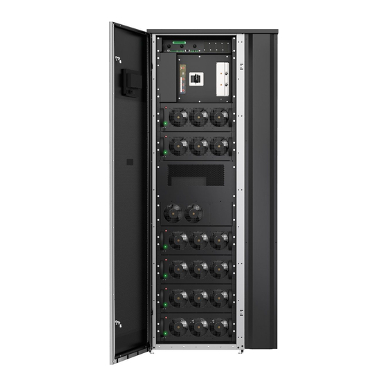
Each UPS cabinet has a centralized system static bypass. Eaton 93PM G2 output power ratings are based on 50 kVA and 60 kVA rated uninterruptible power modules (UPMs) installed in 200/240 kVA or 300/360 kVA UPS frames. - Page 20 Eaton 93PM G2 UPS 50 – 360 kVA User’s and Installation Guide Figure 2: Main parts, outside 1. Control panel 3. Bolts 2. Door 4. Right panel © Eaton Corporation plc 2020. All rights reserved. Revision: 001 Document ID: P-164000956...
- Page 21 Eaton 93PM G2 UPS 50 – 360 kVA User’s and Installation Guide Figure 3: Main parts, inside 1. UPM 1 7. Communication interface 2. UPM 2 8. Internal battery breaker (option) 3. UPM 3 9. Connector area 4. UPM 4 10.
-
Page 22: Ups Operating Modes
Eaton 93PM G2 UPS 50 – 360 kVA User’s and Installation Guide Figure 4: Main parts with MBS, inside 1. UPM 1 9. Maintenance bypass switch (MBS) S2 2. UPM 2 10. Handle for the maintenance 3. UPM 3 bypass switch (MBS) 4. -
Page 23: Normal Operating Modes
Eaton 93PM G2 UPS 50 – 360 kVA User’s and Installation Guide Operating mode Description Normal operating modes: Double conversion mode Critical load is supplied by the inverter, which derives its power from rectified utility AC power. In this mode, the DC/DC converter also provides charging current for the DC source, if needed. - Page 24 Eaton 93PM G2 UPS 50 – 360 kVA User’s and Installation Guide 3.3.1.1 Double conversion mode Figure 5: Path of current through the UPS in the double conversion mode shows the path of electrical power through the UPS system when the UPS is operating in the double conversion mode.
- Page 25 Eaton 93PM G2 UPS 50 – 360 kVA User’s and Installation Guide The inverter produces a three-phase AC output to the critical load. The inverter uses multilevel converter technology with IGBT devices and pulse-width modulation (PWM) to produce a regulated and filtered AC output.
- Page 26 Eaton 93PM G2 UPS 50 – 360 kVA User’s and Installation Guide 3.3.1.3 Energy Saver System mode Figure 6: Path of current through the UPS in the Energy Saver System mode shows the path of electrical power through the UPS system when the UPS is operating in the Energy Saver System (ESS) mode.
-
Page 27: Stored Energy And Battery Mode
Eaton 93PM G2 UPS 50 – 360 kVA User’s and Installation Guide In the ESS mode, the UPS safely provides mains current directly to the load when the input is within the acceptable limits by its voltage and frequency. The UPS status indicated on the display is Unit Online ESS, and the UPM status is Active. - Page 28 Eaton 93PM G2 UPS 50 – 360 kVA User’s and Installation Guide Figure 7: Path of current through the UPS in the battery mode Static switch Bypass input Main power flow Rectifier Rectifier input Energized Inverter Output De-energized DC/DC Battery breaker...
-
Page 29: Bypass Mode
Eaton 93PM G2 UPS 50 – 360 kVA User’s and Installation Guide If the input power fails to return or is not within the acceptance windows required for normal operation, the DC/DC converter continues discharging until a DC voltage level is reached where the inverter output can no longer support the connected loads. - Page 30 Eaton 93PM G2 UPS 50 – 360 kVA User’s and Installation Guide Figure 8: Path of current through the UPS in the bypass mode Static switch Bypass input Main power flow Rectifier Rectifier input Energized Inverter Output De-energized DC/DC Battery breaker...
-
Page 31: Ups Features
The Eaton Powerware Hot Sync technology is an algorithm that eliminates the single point of failure in a parallel system and therefore enhances system reliability. The Hot Sync technology is incorporated in all Eaton UPSs, and it is utilized in both multi-module internal parallel and external parallel systems. -
Page 32: Power Conditioner
3.4.5 Sync Control The Eaton® Sync Control maintains the critical load outputs of two separate single UPS systems in synchronization. Use of the Eaton Fixed Master Sync Control provides uninterrupted transfer of the load from one load bus to another by means of downstream, dual-source, solid-state transfer switches. -
Page 33: Software And Connectivity Features
Refer to Section 4.4 Site preparations for further information. 3.6.3 Single feed kit The Eaton 93PM G2 UPS is configured for dual feed by standard, requiring a separate feed for rectifier and static bypass input. Single feed kit is available both as factory installed or on-site installed option. -
Page 34: Internal Battery Breaker
The UPS can be equipped with an external battery system. Eaton offers external battery cabinets to be used together with the Eaton 93PM G2 UPS. -
Page 35: Basic System Configurations
Eaton 93PM G2 UPS 50 – 360 kVA User’s and Installation Guide Figure 9: External Battery Switchgear cabling diagram 1. External Battery Switchgear 5. String breaker n 2. Breaker 6. Battery cabinet 1 3. UPS 7. Battery cabinet n 4. String breaker 1... - Page 36 Eaton 93PM G2 UPS 50 – 360 kVA User’s and Installation Guide Frame Power Static switch # of power Power Output rating rating modules module power rating factor 360 kVa 60-360 kVa 360 kVa The UPS frames can be connected in parallel to create even larger systems. A maximum of four UPSs can be connected in parallel.
-
Page 37: Ups Installation Plan And Unpacking
NOTE: Startup and operational checks must be performed by an authorized Eaton Customer Service Engineer or by other qualified service personnel authorized by Eaton, or the terms specified in the Warranty (see Chapter 10.2 Whom to contact in case of Warranty) become void. This service is offered as a part of the sales contract for the UPS. -
Page 38: Site Preparations
Eaton 93PM G2 UPS 50 – 360 kVA User’s and Installation Guide Action Yes/No Neutral conductors are installed and bonded to ground according to the requirements. A ground conductor is properly installed. Battery cables are terminated and connected to battery connectors. -
Page 39: Environmental Considerations
Eaton 93PM G2 UPS 50 – 360 kVA User’s and Installation Guide 4.4.1 Environmental considerations Install the UPS to a temperature and humidity controlled indoor area, free of conductive contaminants. Do not expose the UPS to direct sunlight or install it near a heat source. - Page 40 Eaton 93PM G2 UPS 50 – 360 kVA User’s and Installation Guide If you do not obey these guidelines your warranty can become void. CAUTION If the unit is installed in an IT network, the voltage between neutral and protective earth during normal operation must be less than 50 V (AC, RMS), 71 V (AC, peak) or 120 V (DC).
- Page 41 Eaton 93PM G2 UPS 50 – 360 kVA User’s and Installation Guide UPS model Shipping weight Installed weight Floor loading [kg/ [kg] [kg] 93PM G2 300(300) 93PM G2 360(360) 0.9 PF Table 5: UPS cabinet dimensions Dimensions (W x D x H) mm...
- Page 42 Eaton 93PM G2 UPS 50 – 360 kVA User’s and Installation Guide The UPS cabinets use forced air cooling to regulate internal component temperature. By standard, air inlets are in the front of the cabinet and outlets are in the back. You must allow clearance in front of and behind each cabinet for proper air circulation.
- Page 43 Eaton 93PM G2 UPS 50 – 360 kVA User’s and Installation Guide • Ambient temperature range: from +0...+40 °C(+0 ...+35 °C for 240 kVA and 360 kVA PF 0.9 models). • Recommended operating range for VRLA batteries: +20...25 °C. •...
-
Page 44: Ups System Power Wiring Preparations
Eaton 93PM G2 UPS 50 – 360 kVA User’s and Installation Guide 4.4.3 UPS system power wiring preparations NOTE: If you install an external maintenance bypass (MBS): • The UPS static bypass input (X2) and UPS rectifier input (X1) must have external isolators to isolate these feeds from the external MBS input during service operations. - Page 45 Eaton 93PM G2 UPS 50 – 360 kVA User’s and Installation Guide Table 8: Recommended multi-core cable and fuse sizes for rectifier input, bypass input and UPS output connections UPS model Rectifier, bypass and mainte- nance bypass input fuse Phase cables [mm...
- Page 46 Eaton 93PM G2 UPS 50 – 360 kVA User’s and Installation Guide CAUTION Make sure that prospective short-circuit current resulting at the input terminals of the UPS is equal or less than conditional short-circuit current declared on the type plate (and technical specification) of the UPS.
- Page 47 Eaton 93PM G2 UPS 50 – 360 kVA User’s and Installation Guide NOTE: UPS power upgrading is possible only if the sizing of the external cables is sufficient. Alternatively, the external cabling must be upgraded as well. Fuses are of the type gG.
- Page 48 Eaton 93PM G2 UPS 50 – 360 kVA User’s and Installation Guide Table 12: Rated and maximum currents for rated power and voltage, rectifier input and UPS output / bypass UPS model Rectifier input UPS output / Rated bypass Rated voltage...
- Page 49 Eaton 93PM G2 UPS 50 – 360 kVA User’s and Installation Guide Table 13: Rated and maximum currents for rated power and voltage, battery UPS model Battery Rated current [A] Maximum current* [A] 93PM G2 50(200) 93PM G2 100(200) 93PM G2 150(200) 93PM G2 200(200) 93PM G2 240(240) 0.9 PF...
- Page 50 Eaton 93PM G2 UPS 50 – 360 kVA User’s and Installation Guide NOTE: External overcurrent protection is not provided by this product, but is required by codes. Refer to Tables 8: Recommended multi-core cable and fuse sizes for rectifier input, bypass input and UPS output connections and 10: Minimum recommended multi-core cable and fuse sizes for battery connection for wiring requirements.
-
Page 51: Unpack And Unload The Ups
Eaton 93PM G2 UPS 50 – 360 kVA User’s and Installation Guide Unpack and unload the UPS Before you start to unpack and unload the UPS, check the TipNTell indicator on the package surface and the DropNTell indicator on the UPS after unpacking (see step 2 below). - Page 52 Eaton 93PM G2 UPS 50 – 360 kVA User’s and Installation Guide Make a visual inspection and make sure that there are no signs of shipping damages. Examine the indicators. See the DropNTell inside the package. © Eaton Corporation plc 2020. All rights reserved.
- Page 53 Eaton 93PM G2 UPS 50 – 360 kVA User’s and Installation Guide Open the UPS package. A ramp used for moving the cabinet off of the pallet is delivered on top of the cabinet. © Eaton Corporation plc 2020. All rights reserved.
- Page 54 Eaton 93PM G2 UPS 50 – 360 kVA User’s and Installation Guide Fasten the ramp to the pallet. Turn the leveling feet counterclockwise to lift them off of the pallet. © Eaton Corporation plc 2020. All rights reserved. Revision: 001...
- Page 55 Eaton 93PM G2 UPS 50 – 360 kVA User’s and Installation Guide Open the door of the cabinet. Remove the bolts on both sides that fasten the shipping brackets to the cabinet and to the pallet. NOTE: After you have removed the shipping brackets, move the cabinet immediately away from the pallet.
- Page 56 Eaton 93PM G2 UPS 50 – 360 kVA User’s and Installation Guide Move the cabinet to its final installation location. Turn the leveling feet clockwise until the cabinet is levelled. 10. To secure the UPS cabinet in position, attach the shipping brackets on both sides of the cabinet with the angle facing outward.
-
Page 57: Ups System Installation
The electrical installation procedure is described in the following section. The installation inspection and the initial start-up of the UPS and installing an extra battery cabinet must be carried out by an authorized Eaton Customer Service Engineer or by other qualified service personnel authorized by Eaton. - Page 58 Eaton 93PM G2 UPS 50 – 360 kVA User’s and Installation Guide Route and connect power wiring. Use movable cable support beams if needed. See Figure 15: Cable support beams. When all wiring is complete, close the right panel and tighten the screws.
- Page 59 Eaton 93PM G2 UPS 50 – 360 kVA User’s and Installation Guide 2. Bottom cable access gland 4. Top cable access gland plate plate 5. Rear communication cable 3. Communication cable access conduit gland plate Figure 15: Cable support beams ©...
- Page 60 Eaton 93PM G2 UPS 50 – 360 kVA User’s and Installation Guide Figure 16: Connector locations with the optional internal MBS switch 1. Battery + 8. Bypass input L2 2. Battery - 9. Bypass input L3 3. Ground (PE) 10. Neutral 4.
-
Page 61: Installing The Battery System
Eaton 93PM G2 UPS 50 – 360 kVA User’s and Installation Guide Figure 17: External DC source breaker trip/status X8 and sync control interface 1. +24V_TRIP_Power 3. BAT_Shunt_DET 2. BAT_Shunt_TRIP 4. GND X11: 1. Bypass L1 6. Output L3 2. Bypass L2 7. -
Page 62: Battery Trip Wiring
The shunt trip coils are energized (controlled) through connector X8. The status signal of the external battery breaker is also connected to connector X8. Status contacts of the Eaton battery breakers are open if the breaker itself is open. -
Page 63: Installing Ups External Battery Cabinet And Battery Power Cabling
Installing UPS external battery cabinet and battery power cabling There is a vast offering of different Eaton external battery cabinets available for the 93PM-G2 UPSs. Please refer to the three-phase accessories offering for further details. See a separate manual for instructions on how to install Eaton external battery cabinets. -
Page 64: Install Interface Connections
None of the inputs are pre-programmed but need to be separately programmed by qualified service personnel. NOTE: When using an external battery system, Eaton recommends you to connect external signal wiring. © Eaton Corporation plc 2020. All rights reserved. -
Page 65: Install Customer Input Signals Interface
Additional relay outputs are available with mini-slot cards. Relay outputs can be configured to be activated by various events. Configuration can be done by an authorized Eaton Customer Service Engineer or by other qualified service personnel authorized by Eaton. © Eaton Corporation plc 2020. All rights reserved. -
Page 66: Industrial Relay Card Interface Connections
Eaton 93PM G2 UPS 50 – 360 kVA User’s and Installation Guide 5.6.4 Industrial Relay Card interface connections Relays K1 through K5 are identical in function. Each output contact function can be assigned by the user. The UPS information may also be configurable. -
Page 67: Install Signal Interface Connections In A Parallel System
Eaton 93PM G2 UPS 50 – 360 kVA User’s and Installation Guide Route and install the LAN and other cables to the appropriate MiniSlot cards. The cable route is through the signal cable canal in the top section of the UPS. - Page 68 Eaton 93PM G2 UPS 50 – 360 kVA User’s and Installation Guide Output The neutrals of all the UPSs must be connected. The shortest length of wire from the source to the UPS must be a minimum of 95% of the length of the longest wire.
- Page 69 Eaton 93PM G2 UPS 50 – 360 kVA User’s and Installation Guide Parallel system cabling Figure 21: Principle of paralleled UPS systems Bypass inputs to UPS 1 Battery UPSs Outputs from UPS 2 Battery UPSs Load UPS 3 MOB1 UPS 4...
-
Page 70: Control Signals Overview
Eaton 93PM G2 UPS 50 – 360 kVA User’s and Installation Guide 5.7.2 Control signals overview Two control signals (External CAN Network, Bypass Pull-Chain) are required for external paralleling. Both of these control signals are fault-tolerant and alarmed when disconnected. - Page 71 Eaton 93PM G2 UPS 50 – 360 kVA User’s and Installation Guide Figure 22: Communication interfaces 1. X9 External parallel interface Figure 23: X9 External parallel interface Figure 24: Simplified CAN and Pull-Chain wiring for parallel UPS system UPS 1...
- Page 72 Eaton 93PM G2 UPS 50 – 360 kVA User’s and Installation Guide Figure 25: CAN and Pull-Chain wiring for parallel UPS with MOBs Note that the shield cable must be connected on one end only. Figure 26: CAN and Pull-Chain wiring for parallel UPS without MOBs...
-
Page 73: Ups System Power Wiring Preparations
Eaton 93PM G2 UPS 50 – 360 kVA User’s and Installation Guide NOTE: NC and NO designations on MOB AUX contacts are defined with the breaker in the OFF (open) position. If the MOB contacts have pigtail leads, use the same wire gauge to connect to the UPS and use the correct crimp connections for the wire gauge. - Page 74 Eaton 93PM G2 UPS 50 – 360 kVA User’s and Installation Guide Table 17: Recommended multi-core cable and fuse sizes for rectifier input, bypass input and UPS output connections UPS model Rectifier, bypass and mainte- nance bypass input fuse Phase cables [mm...
- Page 75 Eaton 93PM G2 UPS 50 – 360 kVA User’s and Installation Guide CAUTION Make sure that prospective short-circuit current resulting at the input terminals of the UPS is equal or less than conditional short-circuit current declared on the type plate (and technical specification) of the UPS.
- Page 76 Eaton 93PM G2 UPS 50 – 360 kVA User’s and Installation Guide NOTE: UPS power upgrading is possible only if the sizing of the external cables is sufficient. Alternatively, the external cabling must be upgraded as well. Fuses are of the type gG.
- Page 77 Eaton 93PM G2 UPS 50 – 360 kVA User’s and Installation Guide Table 21: Rated and maximum currents for rated power and voltage, rectifier input and UPS output / bypass UPS model Rectifier input UPS output / Rated bypass Rated voltage...
- Page 78 Eaton 93PM G2 UPS 50 – 360 kVA User’s and Installation Guide Table 22: Rated and maximum currents for rated power and voltage, battery UPS model Battery Rated current [A] Maximum current* [A] 93PM G2 50(200) 93PM G2 100(200) 93PM G2 150(200) 93PM G2 200(200) 93PM G2 240(240) 0.9 PF...
- Page 79 Eaton 93PM G2 UPS 50 – 360 kVA User’s and Installation Guide NOTE: External overcurrent protection is not provided by this product, but is required by codes. Refer to Tables 17: Recommended multi-core cable and fuse sizes for rectifier input, bypass input and UPS output connections and 19: Minimum recommended multi-core cable and fuse sizes for battery connection for wiring requirements.
-
Page 80: Communication Interfaces
User’s and Installation Guide Communication interfaces About communication interfaces This section describes the communication features of the Eaton 93PM G2 UPS. CAUTION All the communication interfaces are SELV circuits. When connecting to other equipment, make sure that you maintain this characteristic. - Page 81 Eaton 93PM G2 UPS 50 – 360 kVA User’s and Installation Guide • Gigabit Network Card (NETWORK-M2) Enhances the capabilities and protection provided by the UPS by enabling Web and SNMP based remote monitoring and e-mail alarms. The card also enables shutdown of servers and migration of virtual machines through IPM and IPP software.
- Page 82 Eaton 93PM G2 UPS 50 – 360 kVA User’s and Installation Guide Provides remote monitoring through a Web browser interface, e-mail, and a network management system (NMS) using SNMP and connects to a twisted- pair Ethernet (10/100BaseT) network. The card also provides direct...
-
Page 83: Intelligent Power Software
(IPM) application. Intelligent Power Software is delivered on a CD with the UPS. Alternatively, you can download it from the Eaton web page. Some of the advanced features of IPM require a license, contact your Eaton representative for details. 6.1.3... -
Page 84: Configuring Relays
Eaton 93PM G2 UPS 50 – 360 kVA User’s and Installation Guide You can use a normally-closed or normally-open contact. If the state of the contact changes from the state you specify as normal, a signal is issued. You can connect this contact to equipment at your facility (such as a light or an alarm bell) to let you know when an alarm is active on the UPS. - Page 85 Eaton 93PM G2 UPS 50 – 360 kVA User’s and Installation Guide In the sign in window, click the password field containing the 4 dots. Figure 33: Sign in window with the password field Enter the password 0101 and press Select Continue.
- Page 86 Eaton 93PM G2 UPS 50 – 360 kVA User’s and Installation Guide Select from these options: • Native (Alarm) relay It is possible to set 8 different events for the native relay. If any of the set events occurs, the relay is activated •...
- Page 87 Eaton 93PM G2 UPS 50 – 360 kVA User’s and Installation Guide Press OK and Save to save the changes. Figure 36: Entering the codes of the functions that will trigger the relay If you selected one of the MiniSlots, the following default values are available: •...
- Page 88 Eaton 93PM G2 UPS 50 – 360 kVA User’s and Installation Guide Figure 37: Relays 1. Cable exit opening for up to 3. K1 thru K5 terminal connec- 12 mm (½”) conduit tions for relay contacts to op- erator's monitoring 2.
-
Page 89: Ups Operating Instructions
UPS nominal voltage and frequency from the display by selecting Settings→Information. If the UPS need to be operated with another voltage or frequency, contact your closest Eaton office or Eaton authorized partner. NOTE: The UPS is not a measuring device. All the displayed measurements are approximate values only. -
Page 90: Status Indicators
Eaton 93PM G2 UPS 50 – 360 kVA User’s and Installation Guide Figure 38: Parts of the display The display consists of the following parts: Status bar. The status bar displays the UPS name, state, current date and time, meters information, and a sign in/out button. It also shows any active alarms and warnings. - Page 91 Eaton 93PM G2 UPS 50 – 360 kVA User’s and Installation Guide The UPS is in the bypass mode. The critical load is supported by the bypass source. The green Yellow symbol for indicator for normal operation is not illuminated bypass mode when the system is in the bypass mode.
- Page 92 Eaton 93PM G2 UPS 50 – 360 kVA User’s and Installation Guide 7.2.2.2 UPM status color LED indicator Each UPM has a status LED indicator. It is located on the bottom left corner of the UPM front panel. The LEDs are red, green and blue (RGB). The color of the LED shows the state of the UPM.
-
Page 93: System Events
Eaton 93PM G2 UPS 50 – 360 kVA User’s and Installation Guide 7.2.3 System events When the UPS system is running in the double conversion mode, it continually monitors itself and the incoming utility power. In the battery or bypass mode, the UPS may issue alarms to let you know exactly what event caused the change from the double conversion mode. - Page 94 Eaton 93PM G2 UPS 50 – 360 kVA User’s and Installation Guide Main menu Submenu Functions Battery meters Detailed information on UPS or system battery meters. Controls System controls Go Online Go to bypass Turn off Charger Load Off UPS controls...
- Page 95 Eaton 93PM G2 UPS 50 – 360 kVA User’s and Installation Guide Main menu Submenu Functions UPS module map Module map shows the status of each UPM. System overview System overview shows the status and meters summary for each UPS.
-
Page 96: Signing In
Eaton 93PM G2 UPS 50 – 360 kVA User’s and Installation Guide Setting Description Clock Change the date and time, change the clock format or enable/disable NTP clock setup. GSM modem. Call Service Send automatic e-mail to the service center in case of a failure. -
Page 97: System Control Instructions
Eaton 93PM G2 UPS 50 – 360 kVA User’s and Installation Guide Press Continue to return to the previous screen. You have 3 attempts to type in the password. If an incorrect password is given more than 3 times, you need to wait for 30 minutes before trying again. -
Page 98: Start The Ups System In The Bypass Mode
Eaton 93PM G2 UPS 50 – 360 kVA User’s and Installation Guide Wait for the following messages to appear sequentially on the System controls screen: STARTING ONLINE The rectifier and inverter turn on. The DC voltage continues to ramp up to full voltage. -
Page 99: Transfer From The Double Conversion Mode To The Bypass Mode
System mode NOTE: Note that the Energy Saver System mode commands are displayed only if enabled at the factory or by an Eaton authorized Customer Service Engineer. To transfer the critical load to the Energy Saver System mode. In the home screen, press Controls. -
Page 100: Transfer From The Energy Saver System Mode To The Double Conversion Mode
NOTE: Note that the Energy Saver System mode commands are displayed only if enabled at the factory or by an Eaton authorized Customer Service Engineer. To transfer the critical load to the double conversion mode. In the home screen, press Controls. -
Page 101: Shut Down The Ups System And Critical Load
Eaton 93PM G2 UPS 50 – 360 kVA User’s and Installation Guide Select Disable VMMS. The UPS system transfers to the battery mode and then to the double conversion mode. The green status indicator for normal operation is lit in all the UPSs and UPMs in the system. -
Page 102: Control A Single Ups In A Parallel System
Eaton 93PM G2 UPS 50 – 360 kVA User’s and Installation Guide CAUTION Do not attempt to restart the system after Load Off until you have identified and cleared the cause of the shutdown. Control a single UPS in a parallel system 7.5.1... -
Page 103: Shut Down A Single Ups
Eaton 93PM G2 UPS 50 – 360 kVA User’s and Installation Guide 7.5.2 Shut down a single UPS A single UPS in the system can be shut down only if it is redundant. In practice, this means that a UPS is not allowed to be shut down if doing so would lead to an overload condition in the remaining UPSs in the system. -
Page 104: Shut Down The Upms
Eaton 93PM G2 UPS 50 – 360 kVA User’s and Installation Guide In the UPM control screen, select Start module. 10. Wait for the following messages to appear sequentially on the UPM status line: READY ACTIVE The UPM rectifier and inverter turn on and the UPM transfers to the double conversion mode and supplies the critical load. -
Page 105: Use The Remote Emergency Power-Off Switch
When the EPO switch is activated, all power to the critical load is lost. Use this feature only in case of emergency. NOTE: The following instructions are for the EPO switch supplied by Eaton Corporation. If you are using a customer-supplied EPO switch, it may not activate in the same way. - Page 106 Eaton 93PM G2 UPS 50 – 360 kVA User’s and Installation Guide Follow the normal start position: Figure 39: Normal positions of the switches Bypass input Bypass input switch (BIS) Rectifier input Maintenance bypass switch (MBS) UPS output Do the transfer from the double conversion mode to the bypass mode as instructed in Section 7.4.4 Transfer from the double conversion mode to the...
-
Page 107: Turn The Ups From The Maintenance Bypass Mode To The Double Conversion Mode
Eaton 93PM G2 UPS 50 – 360 kVA User’s and Installation Guide Figure 40: Maintenance bypass mode Bypass input (X2) Bypass input switch (BIS) Rectifier input (X1) Maintenance bypass switch (MBS) UPS output (X3) Turn the UPS from the maintenance bypass mode... - Page 108 Eaton 93PM G2 UPS 50 – 360 kVA User’s and Installation Guide Follow the normal start position: Figure 41: Maintenance bypass mode Bypass input Bypass input switch (BIS) Rectifier input Maintenance bypass switch (MBS) UPS output Close the incoming feeder to connect the power to rectifier input terminals (X1).
- Page 109 Eaton 93PM G2 UPS 50 – 360 kVA User’s and Installation Guide Do the transfer from the bypass mode to the double conversion mode: In the home screen, press Controls. Select UPS controls (Single UPS) or System controls (UPS system).
-
Page 110: Ups Maintenance
Eaton 93PM G2 UPS 50 – 360 kVA User’s and Installation Guide UPS maintenance Introduction to UPS maintenance The components inside the UPS cabinet are secured to a sturdy metal frame. All repairable parts and assemblies are located for easy removal with very little disassembly. -
Page 111: Preventive Maintenance
Eaton 93PM G2 UPS 50 – 360 kVA User’s and Installation Guide Figure 43: Warning label Since each battery string is an energy source in itself, opening the battery circuit breaker does not de-energize the voltage within the battery string. -
Page 112: Daily Maintenance
User’s and Installation Guide The majority of the service and maintenance work must be performed by service personnel qualified by Eaton. Only the actions described in Section and Section 8.3.2 Monthly maintenance are allowed to be done by the user. -
Page 113: Annual Maintenance
Eaton 93PM G2 UPS 50 – 360 kVA User’s and Installation Guide 8.3.4 Annual maintenance CAUTION Only authorized personnel that are familiar with the maintenance and servicing of the UPS system are allowed to do annual preventive maintenance. Contact your service representative for more information about service offerings. -
Page 114: Maintenance Training
Obey all the applicable local regulations regarding the storage, handling and disposal of batteries and battery materials. Maintenance training For more information about training and other services, contact your Eaton representative. © Eaton Corporation plc 2020. All rights reserved. -
Page 115: Technical Data
Eaton 93PM G2 UPS 50 – 360 kVA User’s and Installation Guide Technical data About technical data For a complete technical specification, contact your Eaton representative. Due to continuous product improvement programs, specifications are subject to change without notice. Directives and standards... -
Page 116: Ups Environmental Specifications
Eaton 93PM G2 UPS 50 – 360 kVA User’s and Installation Guide ECO Design Directive 2009/125/EC establishing a framework for the setting of eco-design requirements for energy-related products Batteries 2006/66/EC on batteries and accumulators and waste batteries and accumulators Packaging... - Page 117 Eaton 93PM G2 UPS 50 – 360 kVA User’s and Installation Guide ** ) Limit based on ASHRAE 90.1-2013. Rapidly increasing temperature may cause condensation on colder surfaces. For more technical details please refer to the technical specification of the 93PM ©...
-
Page 118: Warranty
The warranty is only valid if the installation inspection and initial startup of the UPS unit is carried out by an authorized Eaton Field Service Engineer or by other qualified service personnel authorized by Eaton. Service and maintenance of the UPS shall also be performed only by an authorized Eaton Field Service Engineer or by other qualified service personnel authorized by Eaton. -
Page 119: 10.2 Whom To Contact In Case Of Warranty
Eaton 93PM G2 UPS 50 – 360 kVA User’s and Installation Guide 10.2 Whom to contact in case of Warranty In case of Warranty, or while unsure if the unit in question is covered by warranty, contact the respective sales organization where the unit was purchased. Have the following information available: •... -
Page 120: Appendix A: Relay Alarms
Eaton 93PM G2 UPS 50 – 360 kVA User’s and Installation Guide APPENDIX A: Relay alarms These alarm codes are for 91PS/93PS/93PM/93PM G2 Modular UPS, 8-500 kVA. Name 24V Power Supply Failed 5V Power Supply Failed ABM Active ABM Enable... - Page 121 Eaton 93PM G2 UPS 50 – 360 kVA User’s and Installation Guide Name Battery Breaker Open/Closed Battery Breaker Open/Closed Battery Current Over Limit Battery DC Over Voltage Battery DCUV Trip Imminent Battery Discharging Battery In Common Battery Installed Battery Installed...
- Page 122 Eaton 93PM G2 UPS 50 – 360 kVA User’s and Installation Guide Name Bypass AC Over Voltage Bypass AC Under Voltage Bypass Breaker Active Bypass Breaker Installed Bypass Command Bypass Hot Bypass Installed Bypass Not Available Bypass Over Temperature Bypass Over Temperature Trip...
- Page 123 Eaton 93PM G2 UPS 50 – 360 kVA User’s and Installation Guide Name Check Pull Chain Check System Type Configuration Error Chimney Ambient Over Temperature Chimney Fan Failed Clear Alarms Clear Call Service Clear Status Command Clear Warranty Reminder Clock Set Done...
- Page 124 Eaton 93PM G2 UPS 50 – 360 kVA User’s and Installation Guide Name Enable ABM Command Enable Auto Calibration Command Enable ESS Command Enable High Alert Command Enable HRS Command Enable Service Mode Command Enable VMMS Command ESS Active ESS Enabled...
- Page 125 Eaton 93PM G2 UPS 50 – 360 kVA User’s and Installation Guide Name HRS Installed I2C Bus Failed Input AC Over Voltage Input AC Under Voltage Input Sync Out of Range Input Sync Out of Range Input Under/ Over Frequency...
- Page 126 Eaton 93PM G2 UPS 50 – 360 kVA User’s and Installation Guide Name Load Power Off Loss of Sync Bus Loss of PWM Sync Low Battery Shutdown Low Battery Warning MBS Installed MCU 24V Power Supply Failed MCU 5V Power Supply Failed...
- Page 127 Eaton 93PM G2 UPS 50 – 360 kVA User’s and Installation Guide Name On MBS, On Bypass On MBS, Starting On MBS, Shutdown On MBS, Unit Online On MBS, VMMS Active On Notice LED Is Lit On Line LED Is Lit...
- Page 128 Eaton 93PM G2 UPS 50 – 360 kVA User’s and Installation Guide Name Phase C Overload PhaseA Overload Level2 PhaseA Overload Level3 PhaseA Overload Level4 PhaseB Overload Level2 PhaseB Overload Level3 PhaseB Overload Level4 PhaseC Overload Level2 PhaseC Overload Level3...
- Page 129 Eaton 93PM G2 UPS 50 – 360 kVA User’s and Installation Guide Name Registration Reminder Remote Emergency Power Off Reset Alarms Command Reset History LOG Restart Command Service Battery Service Reminders Dismissed Service Required Shutdown Command Shutdown Imminent Signal Input 1 On...
- Page 130 Eaton 93PM G2 UPS 50 – 360 kVA User’s and Installation Guide Name Signal Input Forced Maintenance Bypass Signal Input Maintenance Bypass Signal Input MIS Open Signal Input MOB Open Signal Input On Generator Signal Input Remote ESS Command Signal Input Remote Go to Bypass...
- Page 131 Eaton 93PM G2 UPS 50 – 360 kVA User’s and Installation Guide Name Static Switch Active Static Switch On Static Switch Short Stop Boost Charge Command Stop ECT Command STS Ambient Over Temperature STS Fan Failed Summary Notice System Not Redundant...
- Page 132 Eaton 93PM G2 UPS 50 – 360 kVA User’s and Installation Guide Name UPM Critical Parameters Sync In Process UPM EEPROM Checksum Failed UPM Hardware ID Mismatching UPM Hot UPM in Service Mode UPM Normal, On ESS Mode UPM Normal, On VMMS...
- Page 133 Eaton 93PM G2 UPS 50 – 360 kVA User’s and Installation Guide Name UPS On Battery UPS On Bypass UPS On Generator UPS PhaseA Output Overload UPS PhaseA Overload Level2 UPS PhaseA Overload Level3 UPS PhaseA Overload Level4 UPS PhaseB Output Overload...
- Page 134 Eaton 93PM G2 UPS 50 – 360 kVA User’s and Installation Guide Name VMMS Enable VMMS Installed © Eaton Corporation plc 2020. All rights reserved. Revision: 001 Document ID: P-164000956 (141)
-
Page 135: Appendix B: Recommended Secure Hardening Guidelines
Our company also offers Cybersecurity Best Practices whitepapers to its customers that can be referenced at www.eaton.com/ cybersecurity . Category... - Page 136 Eaton 93PM G2 UPS 50 – 360 kVA User’s and Installation Guide Category Description • Do not connect an unauthorized USB device, CD/DVD or SD card for any operation (for example, firmware upgrade, configuration change and boot application change). •...
- Page 137 Eaton 93PM G2 UPS 50 – 360 kVA User’s and Installation Guide Category Description Logging and event Best practices: management • Our company recommends that all administrative and maintenance activities are logged. • Ensure that logs are backed up. Retain the backups for a minimum of 3 months or as per the organization’s security...
- Page 138 Eaton 93PM G2 UPS 50 – 360 kVA User’s and Installation Guide Cybersecurity Best Practices Checklist Reminder (WP910003EN). http:// www.cooperindustries.com/content/dam/public/powersystems/resources/ library/1100_EAS/WP910003EN.pdf NIST SP 800-82 Rev 2, Guide to Industrial Control Systems (ICS) Security, May 2015. https://ics-cert.us-cert.gov/Standards-and-References National Institute of Technology (NIST) Interagency “Guidelines on Firewalls and Firewall Policy, NIST Special Publication 800-41”, October 2009.
-
Page 139: Index
Eaton 93PM G2 UPS 50 – 360 kVA User’s and Installation Guide Index Normal operating modes Battery system Variable Module Management System UPS Battery Switchgear....34 mode........25 Communication interfaces Options and accessories About communication interfaces ..80 Field installed UPM ....... 33 Configuring relays...... - Page 140 Eaton 93PM G2 UPS 50 – 360 kVA User’s and Installation Guide Shut down the UPS system and critical UPS maintenance load ........101 Annual maintenance ....113 Start the UPS system in the double Battery maintenance ....113 conversion mode ......97 Important safety instructions ..110...
- Page 141 Eaton Power Quality Oy Koskelontie 13 FI-02920 Espoo, Finland www.eaton.eu...
Need help?
Do you have a question about the 93PM G2 Series and is the answer not in the manual?
Questions and answers