Eaton 93PM Installation And Operation Manual
20–100 kw (480v) – 100 kw frame
Hide thumbs
Also See for 93PM:
- Installation manual ,
- Installation and operation manual (152 pages) ,
- User and installation manual (126 pages)

Related Manuals for Eaton 93PM


Summary of Contents for Eaton 93PM
- Page 1 ® Eaton 93PM UPS 20–100 kW (480V) – 100 kW Frame Installation and Operation Manual...
- Page 3 ® Eaton 93PM UPS 20–100 kW (480V) – 100 kW Frame Installation and Operation Manual...
- Page 4 Eaton and Mini-Slot are registered trademarks of Eaton or its subsidiaries and affiliates. Modbus is a registered trademark of Schneider Electric. National Electrical Code and NEC are registered trademarks of National Fire Protection Association, Inc.
-
Page 5: Table Of Contents
Sidecar Integrated Accessory Cabinet-Bypass Wiring Installation ....... . Eaton 93PM UPS (20–100 kW, 480V – 100 kW Frame) Installation and Operation Manual P-164000227—Rev 6... - Page 6 Transfer from ESS Mode to Double Conversion Mode........6-19 Eaton 93PM UPS (20–100 kW, 480V – 100 kW Frame) Installation and Operation Manual P-164000227—Rev 6 www.eaton.com/powerquality...
- Page 7 Maintenance Training ..............Eaton 93PM UPS (20–100 kW, 480V – 100 kW Frame) Installation and Operation Manual P-164000227—Rev 6...
- Page 8 WARRANTY ....................Eaton 93PM UPS (20–100 kW, 480V – 100 kW Frame) Installation and Operation Manual P-164000227—Rev 6...
- Page 9 Removing the Sidecar Pallet Skids and Supports – Eaton 93PM UPS ......
- Page 10 Figure 5-12. Eaton 93PM-100-2 UPS System with Three-Breaker Bypass Oneline ......
- Page 11 Eaton 93PM-100-1 and 93PM-100-2 (N+1) ........
-
Page 12: List Of Tables
List of Tables This page intentionally left blank. viii Eaton 93PM UPS (20–100 kW, 480V – 100 kW Frame) Installation and Operation Manual P-164000227—Rev 6 www.eaton.com/powerquality... -
Page 13: Introduction
AC power to protect the customer's load from power failures. The Eaton 93PM 20–100 kW online power protection system is used to prevent loss of valuable electronic information, minimize equipment downtime, and minimize the adverse effect on production equipment due to unexpected power problems. -
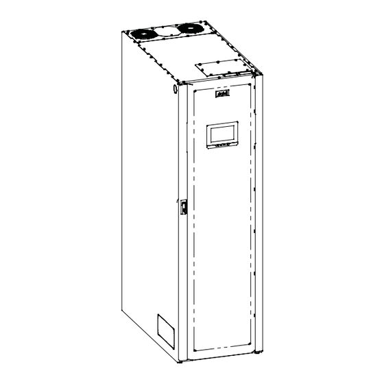
Page 14: Figure 1-1. Eaton 93Pm Ups (20-100 Kw)
Figure 1-1. Eaton 93PM UPS (20–100 kW) UPS with Left-Mounted Sidecar UPS with Right-Mounted Sidecar Figure 1-2. Eaton 93PM UPS (20–100 kW) with Left or Right Mounted Sidecar Eaton 93PM UPS (20–100 kW, 480V – 100 kW Frame) Installation and Operation Manual P-164000227—Rev 6 www.eaton.com/powerquality... -
Page 15: Control Panel
1.1.4 Energy Saver System Mode The 93PM Series UPS offers an Energy Saver System (ESS) mode that maximizes efficiency by eliminating unnecessary power conversion when the commercial power source is within acceptable voltage and frequency limits. In this mode, the UPS is actively monitoring the critical bus and instantly and seamlessly transitions to double-conversion mode (inverter online) if a commercial electrical power brownout, blackout, overvoltage, undervoltage, or out-of-tolerance frequency condition occurs. -
Page 16: Advanced Battery Management
UPS cabinet. The recommended installation location for an adjacent IAC-D is to the left of the UPS cabinet. Eaton 93PM UPS (20–100 kW, 480V – 100 kW Frame) Installation and Operation Manual P-164000227—Rev 6 www.eaton.com/powerquality... -
Page 17: Sidecar Integrated Accessory Cabinet-Bypass
UPS cabinet. The sidecar can be installed on the left or right side of the UPS cabinet. Eaton 93PM UPS (20–100 kW, 480V – 100 kW Frame) Installation and Operation Manual P-164000227—Rev 6 www.eaton.com/powerquality... -
Page 18: Monitoring And Communication
UPS from virtually any location within the facility, up to 300 feet from the UPS. Refer to the Eaton 93PM Remote Monitoring Device (RMD) Installation and Operation Manual, listed in paragraph 1.8, for additional information. -
Page 19: Using This Manual
Introduction Using This Manual This manual describes how to install and operate the Eaton 93PM 20–100 kW. Read and understand the procedures described in this manual to ensure trouble-free installation and operation. In particular, be thoroughly familiar with the REPO procedure (see paragraph 6.3.16 or 6.4.18) or the LOAD OFF procedure (see paragraph 6.3.15 or 6.4.17). -
Page 20: Symbols, Controls, And Indicators
This symbol indicates that you should not discard waste electrical or electronic equipment (WEEE) in the trash. For proper disposal, contact your local recycling/reuse or hazardous waste center. Eaton 93PM UPS (20–100 kW, 480V – 100 kW Frame) Installation and Operation Manual P-164000227—Rev 6 www.eaton.com/powerquality... -
Page 21: For More Information
Introduction For More Information Refer to the Eaton 93PM Integrated Battery Cabinet Installation Manual – Large and Large High Rate, or the Eaton 93PM Universal Integrated Battery Cabinet Installation Manual-Large and Large High Rate, the Eaton 93PM Integrated Battery Cabinet Installation Manual-Small, or the Eaton 93PM Integrated Battery... -
Page 22: Getting Help
Call your local service representative Please use the following e-mail address for manual comments, suggestions, or to report an error in this manual: E-ESSDocumentation@eaton.com 1-10 Eaton 93PM UPS (20–100 kW, 480V – 100 kW Frame) Installation and Operation Manual P-164000227—Rev 6 www.eaton.com/powerquality... -
Page 23: Safety Warnings
Attempting to alter wiring can cause injury. Do not open or mutilate batteries. Released electrolyte is harmful to the skin and eyes. It may be toxic. Eaton 93PM UPS (20–100 kW, 480V – 100 kW Frame) Installation and Operation Manual P-164000227—Rev 6 www.eaton.com/powerquality... - Page 24 Dissiper l'électricité statique de votre corps en touchant une surface reliée à la terre avant de toucher les accumulateurs. Eaton 93PM UPS (20–100 kW, 480V – 100 kW Frame) Installation and Operation Manual P-164000227—Rev 6 www.eaton.com/powerquality...
-
Page 25: Section 1 - Installation
Section 1 Installation... -
Page 27: Ups Installation Plan And Unpacking
The system must be installed in a temperature and humidity controlled indoor area free of conductive contaminants. The environmental requirements specified below are for the air at the intake ports of the 93PM UPS, and are the maximum, not to exceed, ratings. - Page 28 Operating temperatures above the recommended range will result in decreased battery life and performance, and may reduce or void the battery warranty. Eaton 93PM UPS (20–100 kW, 480V – 100 kW Frame) Installation and Operation Manual P-164000227—Rev 6 www.eaton.com/powerquality...
-
Page 29: Table 3-1. Air Conditioning Or Ventilation Requirements During Full Load Operation
The UPS ventilation requirements are shown in Table 3-1. To allow for future power upgrades, Eaton recommends using air conditioning or ventilation sized for the fully rated UPS kW frame size installed instead of the derated kW ordered. Sizing the site cooling infrastructure to be capable of cooling the maximum kW frame size will allow a full power rating upgrade without having to modify the infrastructure. -
Page 30: Table 3-2. Ups Cabinet Weights
Left-Mounted or Right-Mounted SIAC-B UPS Top Entry Wiring Sidecar (no breakers) — — 74 (162) — Four breaker SIAC-B — — 106 (233) — Eaton 93PM UPS (20–100 kW, 480V – 100 kW Frame) Installation and Operation Manual P-164000227—Rev 6 www.eaton.com/powerquality... -
Page 31: Table 3-3. Ups Cabinet Clearances
From Back of Cabinet – Seismic Installation 914.4 mm (36") working space From Right Side of Cabinet None Required From Left Side of Cabinet None Required Eaton 93PM UPS (20–100 kW, 480V – 100 kW Frame) Installation and Operation Manual P-164000227—Rev 6 www.eaton.com/powerquality... -
Page 32: Figure 3-1. Ups Cabinet Dimensions (Front And Right Side Views)
UPS Installation Plan and Unpacking Right Side Front Dimensions are in millimeters [inches] Figure 3-1. UPS Cabinet Dimensions (Front and Right Side Views) Eaton 93PM UPS (20–100 kW, 480V – 100 kW Frame) Installation and Operation Manual P-164000227—Rev 6 www.eaton.com/powerquality... -
Page 33: Figure 3-2. Ups Cabinet Dimensions (Top And Bottom Views)
UPS Installation Plan and Unpacking Front Bottom Front NOTE Top exhaust configuration shown. Dimensions are in millimeters [inches] Figure 3-2. UPS Cabinet Dimensions (Top and Bottom Views) Eaton 93PM UPS (20–100 kW, 480V – 100 kW Frame) Installation and Operation Manual P-164000227—Rev 6 www.eaton.com/powerquality... -
Page 34: Figure 3-3. Ups Cabinet Front And Back Floor Mounting Bracket Mounting Dimensions (Back Views)
UPS Installation Plan and Unpacking UPS with Sidecar Figure 3-3. UPS Cabinet Front and Back Floor Mounting Bracket Mounting Dimensions (Back Views) Eaton 93PM UPS (20–100 kW, 480V – 100 kW Frame) Installation and Operation Manual P-164000227—Rev 6 www.eaton.com/powerquality... -
Page 35: Figure 3-4. Ups Cabinet With Left-Mounted Or Right-Mounted Sidecar Dimensions (Front And Right Side Views)
UPS With Left-Mounted Sidecar Dimensions are in millimeters [inches] Figure 3-4. UPS Cabinet with Left-Mounted or Right-Mounted Sidecar Dimensions (Front and Right Side Views) Eaton 93PM UPS (20–100 kW, 480V – 100 kW Frame) Installation and Operation Manual P-164000227—Rev 6 www.eaton.com/powerquality... -
Page 36: Figure 3-5. Ups Cabinet With Left-Mounted Or Right-Mounted Sidecar Dimensions (Top And Bottom Views)
UPS With Right-Mounted Sidecar Dimensions are in millimeters [inches] Figure 3-5. UPS Cabinet with Left-Mounted or Right-Mounted Sidecar Dimensions (Top and Bottom Views) 3-10 Eaton 93PM UPS (20–100 kW, 480V – 100 kW Frame) Installation and Operation Manual P-164000227—Rev 6 www.eaton.com/powerquality... -
Page 37: Figure 3-6. Ups Cabinet Center Of Gravity
276 (10.8) 406 (896) Eaton 93PM-100-3 UPS Redundant 1022 (40.2) 537 (21.1) 276 (10.8) 470 (1037) Figure 3-6. UPS Cabinet Center of Gravity Eaton 93PM UPS (20–100 kW, 480V – 100 kW Frame) Installation and Operation Manual P-164000227—Rev 6 www.eaton.com/powerquality 3-11... -
Page 38: Figure 3-7. Ups Cabinet With Left-Mounted Or Right-Mounted Sidecar Center Of Gravity
UPS Installation Plan and Unpacking Dimensions are in millimeters [inches] Figure 3-7. UPS Cabinet with Left-Mounted or Right-Mounted Sidecar Center of Gravity 3-12 Eaton 93PM UPS (20–100 kW, 480V – 100 kW Frame) Installation and Operation Manual P-164000227—Rev 6 www.eaton.com/powerquality... -
Page 39: Figure 3-8. Remote Epo Switch Dimensions
Needed to remove key Front View 1/2" Knockout Pattern (Typical 5 Sides Dimensions are in millimeters [inches] Figure 3-8. Remote EPO Switch Dimensions Eaton 93PM UPS (20–100 kW, 480V – 100 kW Frame) Installation and Operation Manual P-164000227—Rev 6 www.eaton.com/powerquality 3-13... -
Page 40: Ups System Power Wiring Preparation
Phase rotation must be clockwise starting with phase A (rotation A,B,C). Material and labor for external wiring requirements are to be supplied by designated personnel. 3-14 Eaton 93PM UPS (20–100 kW, 480V – 100 kW Frame) Installation and Operation Manual P-164000227—Rev 6 www.eaton.com/powerquality... -
Page 41: External Parallel Ups System Power Wiring Preparation
External parallel system wiring length should be in accordance with Figure 3-9, to ensure approximately equal current sharing when in bypass mode. Eaton 93PM UPS (20–100 kW, 480V – 100 kW Frame) Installation and Operation Manual P-164000227—Rev 6 www.eaton.com/powerquality 3-15... -
Page 42: Figure 3-9. 93Pm External Parallel Wire Length
10%. Figure 3-9. 93PM External Parallel Wire Length 3-16 Eaton 93PM UPS (20–100 kW, 480V – 100 kW Frame) Installation and Operation Manual P-164000227—Rev 6 www.eaton.com/powerquality... -
Page 43: Table 3-4. Input/Output Ratings And External Wiring Recommendations For The Eaton 93Pm-100-1 And 93Pm-100-2 (N+1)
Figure 5-6 through Figure 5-13. rating NOTE Line-up-and-match battery wiring with a 105°C is factory supplied with the Eaton 93PM Integrated Battery Cabinet (IBC). Eaton 93PM UPS (20–100 kW, 480V – 100 kW Frame) Installation and Operation Manual P-164000227—Rev 6 www.eaton.com/powerquality 3-17... -
Page 44: Table 3-5. Input/Output Ratings And External Wiring Recommendations For The Eaton 93Pm-100-2 And 93Pm-100-3 (N+1)
Figure 5-10 through Figure 5-17. rating NOTE Line-up-and-match battery wiring with a 105°C is factory supplied with the Eaton 93PM Integrated Battery Cabinet (IBC). 3-18 Eaton 93PM UPS (20–100 kW, 480V – 100 kW Frame) Installation and Operation Manual P-164000227—Rev 6 www.eaton.com/powerquality... -
Page 45: Table 3-6. Ups External Power Cable Terminations For The Eaton 93Pm-100-1, 93Pm-100-2, And 93Pm-100-3
NOTE Customer ground, sized in accordance with NEC Table 250.122, can be run in any conduit listed in Table 3-7 or Table 3-8. Eaton 93PM UPS (20–100 kW, 480V – 100 kW Frame) Installation and Operation Manual P-164000227—Rev 6 www.eaton.com/powerquality... -
Page 46: Table 3-7. Power Cable Conduit Recommendations For The Eaton 93Pm-100-1 And Eaton 93Pm-100-2 (N+1)
Eaton 93PM-100-1 50 kW Eaton 93PM-100-2 (N+1) (A, B, C, Ground) Battery 2-1/2 (Positive, Negative, Ground) NOTE Wires per conduit include ground wire. 3-20 Eaton 93PM UPS (20–100 kW, 480V – 100 kW Frame) Installation and Operation Manual P-164000227—Rev 6 www.eaton.com/powerquality... -
Page 47: Table 3-8. Power Cable Conduit Recommendations For The Eaton 93Pm-100-2 And Eaton 93Pm-100-3 (N+1)
Eaton 93PM-100-2 100 kW Eaton 93PM-100-3 (N+1) (A, B, C, Ground) Battery 2-1/2 (Positive, Negative, Ground) NOTE Wires per conduit include ground wire. Eaton 93PM UPS (20–100 kW, 480V – 100 kW Frame) Installation and Operation Manual P-164000227—Rev 6 www.eaton.com/powerquality 3-21... -
Page 48: Table 3-9. Recommended Input And Bypass Circuit Breaker Ratings
To reduce the risk of fire, connect only to a circuit provided with maximum input circuit breaker current ratings from Table 3-9 in accordance with the NEC, ANSI/NFPA 70. 3-22 Eaton 93PM UPS (20–100 kW, 480V – 100 kW Frame) Installation and Operation Manual P-164000227—Rev 6 www.eaton.com/powerquality... -
Page 49: Table 3-10. Recommended Output Circuit Breaker Ratings
Eaton 93PM-100-2 90 kW Eaton 93PM-100-3 (N+1) 100% Rated 110A 80% Rated 150A Eaton 93PM-100-2 100 kW Eaton 93PM-100-3 (N+1) 100% Rated 125A Eaton 93PM UPS (20–100 kW, 480V – 100 kW Frame) Installation and Operation Manual P-164000227—Rev 6 www.eaton.com/powerquality 3-23... -
Page 50: Table 3-11. Recommended Dc Input Battery Disconnect Circuit Breaker Ratings (216 Cell)
Eaton 93PM-100-3 (N+1) Eaton 93PM-100-2 90 kW 100% Rated 300A Eaton 93PM-100-3 (N+1) Eaton 93PM-100-2 100 kW 100% Rated 300A Eaton 93PM-100-3 (N+1) 3-24 Eaton 93PM UPS (20–100 kW, 480V – 100 kW Frame) Installation and Operation Manual P-164000227—Rev 6 www.eaton.com/powerquality... -
Page 51: Table 3-12. Recommended Dc Input Battery Disconnect Circuit Breaker Ratings (240 Cell)
Eaton 93PM-100-3 (N+1) Eaton 93PM-100-2 90 kW 100% Rated 250A Eaton 93PM-100-3 (N+1) Eaton 93PM-100-2 100 kW 100% Rated 300A Eaton 93PM-100-3 (N+1) Eaton 93PM UPS (20–100 kW, 480V – 100 kW Frame) Installation and Operation Manual P-164000227—Rev 6 www.eaton.com/powerquality 3-25... -
Page 52: Ups System Interface Wiring Preparation
REPO wiring should be a minimum of 18 AWG and a maximum of 16 AWG. The REPO switch wiring must be in accordance with NEC Article 725 Class 2 requirements. 3-26 Eaton 93PM UPS (20–100 kW, 480V – 100 kW Frame) Installation and Operation Manual P-164000227—Rev 6 www.eaton.com/powerquality... -
Page 53: Inspecting And Unpacking The Ups Cabinets
Carefully inspect the outer packaging for evidence of damage during transit. CAUTION Do not install a damaged cabinet. Report any damage to the carrier and contact an Eaton service representative immediately. NOTE For the following step, verify that the forklift or pallet jack is rated to handle the weight of the cabinet (see Table 3-2 for cabinet weight). -
Page 54: Figure 3-10. Ups Cabinet As Shipped On Pallet
UPS Installation Plan and Unpacking Figure 3-10. UPS Cabinet as Shipped on Pallet 3-28 Eaton 93PM UPS (20–100 kW, 480V – 100 kW Frame) Installation and Operation Manual P-164000227—Rev 6 www.eaton.com/powerquality... -
Page 55: Figure 3-11. Ups Cabinet With Left-Mounted Or Right-Mounted Sidecar As Shipped On Pallet
UPS Installation Plan and Unpacking UPS with Left-Mounted Sidecar UPS with Right-Mounted Sidecar Figure 3-11. UPS Cabinet with Left-Mounted or Right-Mounted Sidecar as Shipped on Pallet Eaton 93PM UPS (20–100 kW, 480V – 100 kW Frame) Installation and Operation Manual P-164000227—Rev 6 www.eaton.com/powerquality 3-29... - Page 56 UPS Installation Plan and Unpacking This page intentionally left blank. 3-30 Eaton 93PM UPS (20–100 kW, 480V – 100 kW Frame) Installation and Operation Manual P-164000227—Rev 6 www.eaton.com/powerquality...
-
Page 57: Ups System Installation
Figure 4-1. Place a floor protector from the parts kit underneath each jacking bolt, and screw the bolts down against them. The floor protectors protect the floor from being marred by the jacking bolts. Eaton 93PM UPS (20–100 kW, 480V – 100 kW Frame) Installation and Operation Manual P-164000227—Rev 6 www.eaton.com/powerquality... -
Page 58: Figure 4-1. Removing The Pallet Skids And Supports - Eaton 93Pm Ups
CABINET MAY TIP . Raise the UPS no more than 3 mm (1/8") above the floor (just enough to allow the removal of the pallet skids). Eaton 93PM UPS (20–100 kW, 480V – 100 kW Frame) Installation and Operation Manual P-164000227—Rev 6 www.eaton.com/powerquality... -
Page 59: Figure 4-2. Removing The Sidecar Pallet Skids And Supports - Eaton 93Pm Ups
13. If a sidecar is attached to the UPS, remove the bottom screw securing the sidecar front panel. Lift the panel straight up to remove from the panel hanger brackets at the top of the cabinet. Eaton 93PM UPS (20–100 kW, 480V – 100 kW Frame) Installation and Operation Manual P-164000227—Rev 6 www.eaton.com/powerquality... - Page 60 30. Locate the black cover dots from the parts kit and install over the left and right side bracket mounting holes. 31. Proceed to paragraph 4.3. Eaton 93PM UPS (20–100 kW, 480V – 100 kW Frame) Installation and Operation Manual P-164000227—Rev 6 www.eaton.com/powerquality...
-
Page 61: Integrated Battery Cabinet Installation
Sidecar Integrated Accessory Cabinet-Bypass Wiring Installation If an SIAC-B is attached to the UPS, refer to the Eaton 93PM Sidecar Integrated Accessory Cabinet-Bypass Installation and Operation (50 kW and 100 kW SIAC-B) Manual, listed in paragraph 1.8, for wiring installation instructions. -
Page 62: Sidecar Integrated Accessory Cabinet-Tie Wiring Installation
Sidecar Integrated Accessory Cabinet-Tie Wiring Installation If an SIAC-T is attached to the UPS, refer to the Eaton 93PM Sidecar Integrated Accessory Cabinet-Tie and Tie Bypass (50 kW and 100 kW SIAC-T, and 50 kW and 100 kW SIAC-TB) Installation and Operation Manual, listed in paragraph 1.8, for wiring installation instructions. - Page 63 See Figure 4-7 for UPS terminal locations. For a detailed view of the UPS ground terminals, see Figure 4-8. 18. Proceed to paragraph 4.10. Eaton 93PM UPS (20–100 kW, 480V – 100 kW Frame) Installation and Operation Manual P-164000227—Rev 6 www.eaton.com/powerquality...
-
Page 64: Figure 4-4. Ups Conduit And Wire Entry Locations
Top Entry Conduit Landings for Customer Interface Wiring (Remove panels to drill or punch conduit holes.) Figure 4-4. UPS Conduit and Wire Entry Locations Eaton 93PM UPS (20–100 kW, 480V – 100 kW Frame) Installation and Operation Manual P-164000227—Rev 6 www.eaton.com/powerquality... -
Page 65: Figure 4-5. Sidecar Conduit And Wire Entry Locations
Input and Output, and DC Input (Remove panel to drill or punch conduit holes.) Front UPS with Right -Mounted Sidecar Figure 4-5. Sidecar Conduit and Wire Entry Locations Eaton 93PM UPS (20–100 kW, 480V – 100 kW Frame) Installation and Operation Manual P-164000227—Rev 6 www.eaton.com/powerquality... -
Page 66: Figure 4-6. Ups Inter-Cabinet Wiring Access Location
Right Side View Inter-cabinet wiring access knockouts. Remove knockouts as required to route power wiring between cabinets. Figure 4-6. UPS Inter-Cabinet Wiring Access Location 4-10 Eaton 93PM UPS (20–100 kW, 480V – 100 kW Frame) Installation and Operation Manual P-164000227—Rev 6 www.eaton.com/powerquality... -
Page 67: Figure 4-7. Power Terminal Locations
(A, B, C) (A, B, C) (See Figure 4-8 for detail.) (See Figure 4-8 for detail.) Front Figure 4-7. Power Terminal Locations Eaton 93PM UPS (20–100 kW, 480V – 100 kW Frame) Installation and Operation Manual P-164000227—Rev 6 www.eaton.com/powerquality 4-11... -
Page 68: Figure 4-8. Power Terminal Detail
If removed, reinstall the sidecar front panel and secure with the retained hardware. Close the UPS outside door and secure the latch. 4-12 Eaton 93PM UPS (20–100 kW, 480V – 100 kW Frame) Installation and Operation Manual P-164000227—Rev 6 www.eaton.com/powerquality... -
Page 69: Installing Interface Connections
14. Connect the relay output interface wiring to the relay output terminals. See paragraph 3.2.4 and Table 4-2 for wiring and termination requirements, and Figure 4-14 for terminal assignments. Eaton 93PM UPS (20–100 kW, 480V – 100 kW Frame) Installation and Operation Manual P-164000227—Rev 6 www.eaton.com/powerquality... -
Page 70: Figure 4-9. Interface Terminal Locations
(See Figure 4-10 for detail.) (See Figure 4-10 for detail.) Pull Chain and CAN Terminals (See Figure 4-10 for detail.) Front Figure 4-9. Interface Terminal Locations 4-14 Eaton 93PM UPS (20–100 kW, 480V – 100 kW Frame) Installation and Operation Manual P-164000227—Rev 6 www.eaton.com/powerquality... -
Page 71: Figure 4-10. Interface Terminal Detail
(See Figure 4-12 for detail.) Bottom Access Interface Wiring Channel Bottom Entry Conduit Landings for Customer Interface Wiring Figure 4-11. Bottom Access Interface Wiring Location Eaton 93PM UPS (20–100 kW, 480V – 100 kW Frame) Installation and Operation Manual P-164000227—Rev 6 www.eaton.com/powerquality 4-15... -
Page 72: Figure 4-12. Wire Tie Anchors
Building Alarm 4 Building Alarm 2 Return Building Alarm 3 Building Alarm 3 Return Figure 4-13. Building Alarm Terminal Block Connector Assignments 4-16 Eaton 93PM UPS (20–100 kW, 480V – 100 kW Frame) Installation and Operation Manual P-164000227—Rev 6 www.eaton.com/powerquality... -
Page 73: Figure 4-14. Relay Contact Terminal Block Connector Assignments
UPS building alarm terminals. See Figure 4-6 for UPS wiring access information, and Figure 4-9 and Figure 4-10 for UPS terminal locations. Refer to the Eaton 93PM Integrated Battery Cabinet Installation Manual – Large and Large High Rate, the Eaton 93PM... -
Page 74: Installing Battery Shunt Trip Interface Connections
(see Figure 4-11). Refer to the Eaton 93PM Integrated Battery Cabinet Installation Manual – Large and Large High Rate, the Eaton 93PM Universal Integrated Battery Cabinet Installation Manual-Large and Large High Rate, the Eaton 93PM Integrated Battery Cabinet Installation Manual-Small, or the Eaton 93PM Integrated Battery Cabinet-Small Welded IBC-SW (432V and 480V) Installation Manual, listed in paragraph 1.8, for... - Page 75 See Figure 4-4 for UPS wiring access information, and Figure 4-15 and Figure 4-16 for UPS terminal locations. Refer to the Eaton 93PM Integrated Battery Cabinet Installation Manual – Large and Large High Rate, the Eaton 93PM Universal Integrated Battery Cabinet Installation Manual-Large and Large High Rate, the Eaton 93PM Integrated Battery Cabinet Installation Manual-Small, or the Eaton 93PM Integrated Battery Cabinet-Small Welded IBC-SW (432V and 480V) Installation Manual, listed in paragraph 1.8, for...
-
Page 76: Figure 4-15. Battery Shunt Trip Location
UPS System Installation Shunt Trip Terminals (See Figure 4-16 for detail.) Figure 4-15. Battery Shunt Trip Location 4-20 Eaton 93PM UPS (20–100 kW, 480V – 100 kW Frame) Installation and Operation Manual P-164000227—Rev 6 www.eaton.com/powerquality... -
Page 77: Figure 4-16. Battery Shunt Trip Terminal Detail
Shunt Trip Terminals Not Used Not Used Battery Shunt Trip – Battery Shunt Trip + Figure 4-17. Battery Shunt Trip Terminal Assignments Eaton 93PM UPS (20–100 kW, 480V – 100 kW Frame) Installation and Operation Manual P-164000227—Rev 6 www.eaton.com/powerquality 4-21... -
Page 78: Generator Interface Connections
4.11.7; if wiring REPO connections, proceed to paragraph 4.12; otherwise, proceed to Step 15. 15. Close the UPS outside door and secure the latch. 4-22 Eaton 93PM UPS (20–100 kW, 480V – 100 kW Frame) Installation and Operation Manual P-164000227—Rev 6 www.eaton.com/powerquality... -
Page 79: Installing External Parallel Can Control Wiring And Connections
4.11.7; if wiring REPO connections, proceed to paragraph 4.12; otherwise, proceed to Step 17. 17 . Close the UPS outside door and secure the latch. Eaton 93PM UPS (20–100 kW, 480V – 100 kW Frame) Installation and Operation Manual P-164000227—Rev 6 www.eaton.com/powerquality 4-23... -
Page 80: Table 4-4. External Parallel Can And Pull Chain Connections
0.4 (3.5) - 0.8 (7.1) Slotted Use twisted-pair wires for each input and return or common. Strip wire insulation back 10 millimeters to wire terminal blocks. 4-24 Eaton 93PM UPS (20–100 kW, 480V – 100 kW Frame) Installation and Operation Manual P-164000227—Rev 6 www.eaton.com/powerquality... -
Page 81: Figure 4-18. External Parallel Can Wiring
CAN L In External Ground (ISP) Parallel TB Earth CAN H Out CAN L Out Ground (ISP) Earth Figure 4-19. External Parallel Terminal Block Eaton 93PM UPS (20–100 kW, 480V – 100 kW Frame) Installation and Operation Manual P-164000227—Rev 6 www.eaton.com/powerquality 4-25... -
Page 82: Installing External Parallel Pull Chain Control Wiring And Connections
12. Top Entry Wiring. Remove the top interface entry conduit landing plate to drill or punch holes (see Figure 4-4). 13. Reinstall the interface entry plate and install the conduit. 4-26 Eaton 93PM UPS (20–100 kW, 480V – 100 kW Frame) Installation and Operation Manual P-164000227—Rev 6 www.eaton.com/powerquality... -
Page 83: Installing Minislot Interface Connections
15. If wiring REPO connections, proceed to paragraph 4.12; otherwise, proceed to Step 16. 16. Close the UPS outside door and secure the latch. Eaton 93PM UPS (20–100 kW, 480V – 100 kW Frame) Installation and Operation Manual P-164000227—Rev 6 www.eaton.com/powerquality... -
Page 84: Figure 4-20. External Parallel Pull Chain Wiring
Any pair of unused building alarm terminals may be used for the MOB Aux 1 connections. Figure 4-20. External Parallel Pull Chain Wiring 4-28 Eaton 93PM UPS (20–100 kW, 480V – 100 kW Frame) Installation and Operation Manual P-164000227—Rev 6 www.eaton.com/powerquality... -
Page 85: Installing A Repo Switch
Remove the bottom interface entry conduit landing plate to drill or punch holes (see Figure 4-11). 10. Reinstall the interface entry plate and install the conduit. Eaton 93PM UPS (20–100 kW, 480V – 100 kW Frame) Installation and Operation Manual P-164000227—Rev 6 www.eaton.com/powerquality... -
Page 86: Figure 4-21. Repo Switch
18. Close the UPS outside door and secure the latch. UPS REPO Normally Closed EPO_A_B Normally Open EPO_A REPO Contacts REPO Contacts EPO_B GND-ISO Figure 4-22. REPO Terminal Block Connector Assignments 4-30 Eaton 93PM UPS (20–100 kW, 480V – 100 kW Frame) Installation and Operation Manual P-164000227—Rev 6 www.eaton.com/powerquality... -
Page 87: Figure 4-23. Normally-Open Repo Switch Wiring
REPO switch rating is 24 Vdc, 1A minimum. NOTE The REPO switch must be a latching-type switch not tied to any other circuits. Figure 4-24. Normally-Closed REPO Switch Wiring Eaton 93PM UPS (20–100 kW, 480V – 100 kW Frame) Installation and Operation Manual P-164000227—Rev 6 www.eaton.com/powerquality 4-31... -
Page 88: Initial Startup
Eaton Customer Service Engineer, or the warranty terms specified on page W-1 become void. This service is offered as part of the sales contract for the UPS. Contact an Eaton service representative in advance (usually a two-week notice is required) to reserve a preferred startup date. -
Page 89: Installation Checklist
Accessories are mounted in installed locations and wiring is terminated inside the UPS cabinet. (Optional) Air conditioning equipment is installed and operating correctly. The area around the installed UPS system is clean and dust-free. (Eaton recommends that the UPS be installed on a level floor suitable for computer or electronic equipment.) Adequate workspace exists around the UPS and other cabinets. - Page 90 UPS System Installation Notes 4-34 Eaton 93PM UPS (20–100 kW, 480V – 100 kW Frame) Installation and Operation Manual P-164000227—Rev 6 www.eaton.com/powerquality...
- Page 91 Section 2 Operation...
-
Page 93: Figure 5-1. Main Elements Of The Ups System
AC Output Static AC Input to to Critical Switch Bypass Load Bypass Switchgear UPS Cabinet Figure 5-1. Main Elements of the UPS System Eaton 93PM UPS (20–100 kW, 480V – 100 kW Frame) Installation and Operation Manual P-164000227—Rev 6 www.eaton.com/powerquality... -
Page 94: Single Ups
ESS mode is a normal operating mode, and not an alarm condition. While the UPS is in this mode, the NORMAL light on the front display will illuminate. Eaton 93PM UPS (20–100 kW, 480V – 100 kW Frame) Installation and Operation Manual P-164000227—Rev 6 www.eaton.com/powerquality... -
Page 95: Normal Mode
If the UPS suffers an internal failure and is configured for capacity, it switches automatically to Bypass mode and remains in that mode until the failure is corrected and the UPS is back in service. Eaton 93PM UPS (20–100 kW, 480V – 100 kW Frame) Installation and Operation Manual P-164000227—Rev 6 www.eaton.com/powerquality... -
Page 96: Figure 5-3. Path Of Current Through The Ups In Normal Mode
The bypass switchgear is normally closed, ready to support the static switch unless the bypass input source becomes unavailable. Eaton 93PM UPS (20–100 kW, 480V – 100 kW Frame) Installation and Operation Manual P-164000227—Rev 6 www.eaton.com/powerquality... -
Page 97: Figure 5-4. Path Of Current Through The Ups In Bypass Mode
Normal mode. Depending on the total load and the duration of the battery discharge, battery current limit alarms may be seen for a short time due to the current required to recharge the battery. Eaton 93PM UPS (20–100 kW, 480V – 100 kW Frame) Installation and Operation Manual P-164000227—Rev 6 www.eaton.com/powerquality... -
Page 98: Figure 5-5. Path Of Current Through The Ups In Battery Mode
Main Power Flow Battery Switchgear Switchgear Trickle Current Closed Energized Open De-Energized Battery Figure 5-5. Path of Current Through the UPS in Battery Mode Eaton 93PM UPS (20–100 kW, 480V – 100 kW Frame) Installation and Operation Manual P-164000227—Rev 6 www.eaton.com/powerquality... -
Page 99: Single Ups Unit System Oneline Configurations
Single three UPM reverse transfer UPS with three breaker bypass and external battery See Figure 5-17 93PM-100-3 Single three UPM reverse transfer UPS with four breaker bypass and external battery Eaton 93PM UPS (20–100 kW, 480V – 100 kW Frame) Installation and Operation Manual P-164000227—Rev 6 www.eaton.com/powerquality... -
Page 100: Figure 5-6. Eaton 93Pm-100-1 Ups System Oneline
(Not supplied with the UPS.) NOTE Callout letters A, B, C, and D map to Table 3-4. Figure 5-6. Eaton 93PM-100-1 UPS System Oneline Eaton 93PM UPS (20–100 kW, 480V – 100 kW Frame) Installation and Operation Manual P-164000227—Rev 6 www.eaton.com/powerquality... -
Page 101: Figure 5-7. Eaton 93Pm-100-1 Ups System With Two-Breaker Bypass Oneline
(Not supplied with the UPS.) NOTE Callout letters A, B, C, and D map to Table 3-4. Figure 5-7. Eaton 93PM-100-1 UPS System with Two-Breaker Bypass Oneline Eaton 93PM UPS (20–100 kW, 480V – 100 kW Frame) Installation and Operation Manual P-164000227—Rev 6 www.eaton.com/powerquality... -
Page 102: Figure 5-8. Eaton 93Pm-100-1 Ups System With Three-Breaker Bypass Oneline
NOTE Callout letters A, B, C, and D map to Table 3-4. Figure 5-8. Eaton 93PM-100-1 UPS System with Three-Breaker Bypass Oneline 5-10 Eaton 93PM UPS (20–100 kW, 480V – 100 kW Frame) Installation and Operation Manual P-164000227—Rev 6 www.eaton.com/powerquality... -
Page 103: Figure 5-9. Eaton 93Pm-100-1 Ups System With Four-Breaker Bypass Oneline
NOTE Callout letters A, B, C, and D map to Table 3-4. Figure 5-9. Eaton 93PM-100-1 UPS System with Four-Breaker Bypass Oneline Eaton 93PM UPS (20–100 kW, 480V – 100 kW Frame) Installation and Operation Manual P-164000227—Rev 6 www.eaton.com/powerquality 5-11... -
Page 104: Figure 5-10. Eaton 93Pm-100-2 Ups System Oneline
NOTE Callout letters A, B, C, and D map to Table 3-4 or Table 3-5. Figure 5-10. Eaton 93PM-100-2 UPS System Oneline 5-12 Eaton 93PM UPS (20–100 kW, 480V – 100 kW Frame) Installation and Operation Manual P-164000227—Rev 6 www.eaton.com/powerquality... -
Page 105: Figure 5-11. Eaton 93Pm-100-2 Ups System With Two-Breaker Bypass Oneline
NOTE Callout letters A, B, C, and D map to Table 3-4 or Table 3-5. Figure 5-11. Eaton 93PM-100-2 UPS System with Two-Breaker Bypass Oneline Eaton 93PM UPS (20–100 kW, 480V – 100 kW Frame) Installation and Operation Manual P-164000227—Rev 6 www.eaton.com/powerquality... -
Page 106: Figure 5-12. Eaton 93Pm-100-2 Ups System With Three-Breaker Bypass Oneline
NOTE Callout letters A, B, C, and D map to Table 3-4 or Table 3-5. Figure 5-12. Eaton 93PM-100-2 UPS System with Three-Breaker Bypass Oneline 5-14 Eaton 93PM UPS (20–100 kW, 480V – 100 kW Frame) Installation and Operation Manual P-164000227—Rev 6 www.eaton.com/powerquality... -
Page 107: Figure 5-13. Eaton 93Pm-100-2 Ups System With Four-Breaker Bypass Oneline
NOTE Callout letters A, B, C, and D map to Table 3-4 or Table 3-5. Figure 5-13. Eaton 93PM-100-2 UPS System with Four-Breaker Bypass Oneline Eaton 93PM UPS (20–100 kW, 480V – 100 kW Frame) Installation and Operation Manual P-164000227—Rev 6 www.eaton.com/powerquality... -
Page 108: Figure 5-14. Eaton 93Pm-100-3 Ups System Oneline
(Not supplied with the UPS.) NOTE Callout letters A, B, C, and D map to Table 3-5. Figure 5-14. Eaton 93PM-100-3 UPS System Oneline 5-16 Eaton 93PM UPS (20–100 kW, 480V – 100 kW Frame) Installation and Operation Manual P-164000227—Rev 6 www.eaton.com/powerquality... -
Page 109: Figure 5-15. Eaton 93Pm-100-3 Ups System With Two-Breaker Bypass Oneline
NOTE Callout letters A, B, C, and D map to Table 3-5. Figure 5-15. Eaton 93PM-100-3 UPS System with Two-Breaker Bypass Oneline Eaton 93PM UPS (20–100 kW, 480V – 100 kW Frame) Installation and Operation Manual P-164000227—Rev 6 www.eaton.com/powerquality 5-17... -
Page 110: Figure 5-16. Eaton 93Pm-100-3 Ups System With Three-Breaker Bypass Oneline
NOTE Callout letters A, B, C, and D map to Table 3-5. Figure 5-16. Eaton 93PM-100-3 UPS System with Three-Breaker Bypass Oneline 5-18 Eaton 93PM UPS (20–100 kW, 480V – 100 kW Frame) Installation and Operation Manual P-164000227—Rev 6 www.eaton.com/powerquality... -
Page 111: Figure 5-17. Eaton 93Pm-100-3 Ups System With Four-Breaker Bypass Oneline
NOTE Callout letters A, B, C, and D map to Table 3-5. Figure 5-17. Eaton 93PM-100-3 UPS System with Four-Breaker Bypass Oneline Eaton 93PM UPS (20–100 kW, 480V – 100 kW Frame) Installation and Operation Manual P-164000227—Rev 6 www.eaton.com/powerquality 5-19... - Page 112 Understanding UPS Operation This page intentionally left blank. 5-20 Eaton 93PM UPS (20–100 kW, 480V – 100 kW Frame) Installation and Operation Manual P-164000227—Rev 6 www.eaton.com/powerquality...
-
Page 113: Figure 6-1. Ups Controls And Indicators
UPS control panel functions, and how to control and monitor UPS operation., see paragraph 6.2. Control Panel Door Latch Figure 6-1. UPS Controls and Indicators Eaton 93PM UPS (20–100 kW, 480V – 100 kW Frame) Installation and Operation Manual P-164000227—Rev 6 www.eaton.com/powerquality... -
Page 114: Figure 6-2. Ups Control Panel
The following paragraphs describe using the UPS control panel to monitor the UPS. See paragraph 6.3 for use of the operational controls. When the unit powers up, the screen displays the as shown in Figure 6-2. Eaton 93PM UPS (20–100 kW, 480V – 100 kW Frame) Installation and Operation Manual P-164000227—Rev 6 www.eaton.com/powerquality... -
Page 115: Status Indicators
This message is also written to the Events Log and may be added to the History Log. The messages are divided into four categories: alarms, notices, status, and commands. Eaton 93PM UPS (20–100 kW, 480V – 100 kW Frame) Installation and Operation Manual P-164000227—Rev 6 www.eaton.com/powerquality... -
Page 116: Figure 6-3. Parts Of The Lcd
Look at a log of UPS events (alarms, notices, and commands) (see paragraph 6.2.6) Monitor UPS operation (see paragraph 6.2.6) Set UPS parameters (see paragraph 6.2.6) Control UPS operation (see paragraphs 6.2.6 and 6.2.8) Eaton 93PM UPS (20–100 kW, 480V – 100 kW Frame) Installation and Operation Manual P-164000227—Rev 6 www.eaton.com/powerquality... -
Page 117: Figure 6-4. Main Menu And Mimic Screen
The Mimic screen shows the internal components of the UPS cabinet and a real-time graphical representation of the operating status of the system. Figure 6-4. Main Menu and Mimic Screen Eaton 93PM UPS (20–100 kW, 480V – 100 kW Frame) Installation and Operation Manual P-164000227—Rev 6 www.eaton.com/powerquality... -
Page 118: Table 6-3. Display Menu Operation
Tap the STATISTICS tab on the main menu navigation bar to display a summary of UPS statistics (see Figure 6-13). Statistics Details Tap the desired statistic button to display the detailed statistic screen. Controls See paragraph 6.2.8 for details. Eaton 93PM UPS (20–100 kW, 480V – 100 kW Frame) Installation and Operation Manual P-164000227—Rev 6 www.eaton.com/powerquality... -
Page 119: Figure 6-5. Typical Meters Summary Screen
UPS Operating Instructions Figure 6-5. Typical Meters Summary Screen Figure 6-6. Typical Active Events Screen Eaton 93PM UPS (20–100 kW, 480V – 100 kW Frame) Installation and Operation Manual P-164000227—Rev 6 www.eaton.com/powerquality... -
Page 120: Figure 6-7. Typical System Log Screen
UPS Operating Instructions Figure 6-7. Typical System Log Screen Figure 6-8. Typical Settings User Screen Eaton 93PM UPS (20–100 kW, 480V – 100 kW Frame) Installation and Operation Manual P-164000227—Rev 6 www.eaton.com/powerquality... -
Page 121: Figure 6-9. Typical Information Screen
UPS Operating Instructions Figure 6-9. Typical Information Screen Figure 6-10. Typical About Screen Eaton 93PM UPS (20–100 kW, 480V – 100 kW Frame) Installation and Operation Manual P-164000227—Rev 6 www.eaton.com/powerquality... -
Page 122: Figure 6-11. Typical Settings Configuration 1 Screen
UPS Operating Instructions Figure 6-11. Typical Settings Configuration 1 Screen Figure 6-12. Typical Settings Configuration 2 Screen 6-10 Eaton 93PM UPS (20–100 kW, 480V – 100 kW Frame) Installation and Operation Manual P-164000227—Rev 6 www.eaton.com/powerquality... -
Page 123: Figure 6-13. Typical Statistics Screen
Level 1 default password is 1111. Settings Level 2 default password is 0101. Sign in is complete. Tap continue to return to previous screen. Eaton 93PM UPS (20–100 kW, 480V – 100 kW Frame) Installation and Operation Manual P-164000227—Rev 6 www.eaton.com/powerquality... -
Page 124: Figure 6-14. Sign In Password Screen
UPS Operating Instructions Figure 6-14. Sign In Password Screen Figure 6-15. Sign In Keypad 6-12 Eaton 93PM UPS (20–100 kW, 480V – 100 kW Frame) Installation and Operation Manual P-164000227—Rev 6 www.eaton.com/powerquality... -
Page 125: Figure 6-16. Typical System Control Screen
Table 6-5. Typical System Status Messages Function Message Double Conversion; Bypass; ESS Bypass Off; On; Available Charger Charger Resting; Charger Figure 6-16. Typical System Control Screen Eaton 93PM UPS (20–100 kW, 480V – 100 kW Frame) Installation and Operation Manual P-164000227—Rev 6 www.eaton.com/powerquality 6-13... -
Page 126: Figure 6-17. Typical Ups Control Screen
UPS Operating Instructions Figure 6-17. Typical UPS Control Screen Figure 6-18. Typical UPM Select Screen 6-14 Eaton 93PM UPS (20–100 kW, 480V – 100 kW Frame) Installation and Operation Manual P-164000227—Rev 6 www.eaton.com/powerquality... -
Page 127: Figure 6-19. Typical Upm Control Screen
UPS Operating Instructions Figure 6-19. Typical UPM Control Screen Figure 6-20. Typical EAA Control Screen Eaton 93PM UPS (20–100 kW, 480V – 100 kW Frame) Installation and Operation Manual P-164000227—Rev 6 www.eaton.com/powerquality 6-15... -
Page 128: Single Ups Operation
Power is now supplied to the critical load in dual conversion mode. It takes approximately one minute for the UPS to achieve the dual conversion mode. The Normal status indicator is illuminated. 6-16 Eaton 93PM UPS (20–100 kW, 480V – 100 kW Frame) Installation and Operation Manual P-164000227—Rev 6 www.eaton.com/powerquality... -
Page 129: Starting The Ups In Bypass Mode
The UPM 3 rectifier and inverter turn on. When the inverter reaches full voltage, the UPS is ready to transfer to the Double Conversion mode and supply the critical load. Eaton 93PM UPS (20–100 kW, 480V – 100 kW Frame) Installation and Operation Manual P-164000227—Rev 6 www.eaton.com/powerquality... -
Page 130: Starting A Single Upm
The UPS transfers to Double Conversion mode. If the power module is not available, the system remains on bypass and an alarm sounds. The NORMAL status indicator is illuminated. 6-18 Eaton 93PM UPS (20–100 kW, 480V – 100 kW Frame) Installation and Operation Manual P-164000227—Rev 6 www.eaton.com/powerquality... -
Page 131: Transfer From Ess Mode To Double Conversion Mode
Repeat Steps 2 through 5 selecting UPM 3 to shut down UPM 3. The UPM status indicates SHUTDOWN. The power module is turned off. Logic power remains on. Eaton 93PM UPS (20–100 kW, 480V – 100 kW Frame) Installation and Operation Manual P-164000227—Rev 6 www.eaton.com/powerquality 6-19... -
Page 132: Single Upm Shutdown
Open the UPS input feeder circuit breaker. If dual feed, open the UPS bypass feeder circuit breaker. If IBCs are installed, open all battery breakers. 6-20 Eaton 93PM UPS (20–100 kW, 480V – 100 kW Frame) Installation and Operation Manual P-164000227—Rev 6 www.eaton.com/powerquality... -
Page 133: Charger Control
CAUTION Do not attempt to restart the system after Load Off until the cause of the shutdown has been identified and cleared. Eaton 93PM UPS (20–100 kW, 480V – 100 kW Frame) Installation and Operation Manual P-164000227—Rev 6 www.eaton.com/powerquality 6-21... -
Page 134: Using The Remote Emergency Power-Off Switch
Restart the UPS by following the procedure in paragraph 6.3.1 or 6.3.2. WARNING Power is present inside the UPS cabinet until the upstream input feeder circuit breakers and battery breakers are opened. 6-22 Eaton 93PM UPS (20–100 kW, 480V – 100 kW Frame) Installation and Operation Manual P-164000227—Rev 6 www.eaton.com/powerquality... -
Page 135: Figure 6-21. Repo Operation
UPS Operating Instructions Activated Deactivated (Pushbutton locked into place.) (Unlock pushbutton to release.) Figure 6-21. REPO Operation Eaton 93PM UPS (20–100 kW, 480V – 100 kW Frame) Installation and Operation Manual P-164000227—Rev 6 www.eaton.com/powerquality 6-23... -
Page 136: Multiple External Parallel System Operation
Power is now supplied to the critical load in dual conversion mode from all UPSs. It takes approximately one minute for the UPSs to achieve the dual conversion mode. The Normal status indicator is illuminated. 6-24 Eaton 93PM UPS (20–100 kW, 480V – 100 kW Frame) Installation and Operation Manual P-164000227—Rev 6 www.eaton.com/powerquality... -
Page 137: Starting The Parallel System In Bypass Mode
Double Conversion mode and supply the critical load. 11. Repeat Steps 1 through 10 for each UPS in the parallel system. Eaton 93PM UPS (20–100 kW, 480V – 100 kW Frame) Installation and Operation Manual P-164000227—Rev 6 www.eaton.com/powerquality... -
Page 138: Starting A Single Upm
All of the UPSs transfer to Double Conversion mode. If the power module is not available, the system remains on bypass and an alarm sounds. The NORMAL status indicator is illuminated. 6-26 Eaton 93PM UPS (20–100 kW, 480V – 100 kW Frame) Installation and Operation Manual P-164000227—Rev 6 www.eaton.com/powerquality... -
Page 139: Transfer From Ess Mode To Double Conversion Mode
The UPM status indicates SHUTDOWN. The power module is turned off. Logic power remains on. Repeat Steps 2 through 7 for each UPS in the parallel system. Eaton 93PM UPS (20–100 kW, 480V – 100 kW Frame) Installation and Operation Manual P-164000227—Rev 6 www.eaton.com/powerquality 6-27... -
Page 140: Single Upm Shutdown
The UPM status indicates SHUTDOWN. The input, output, and battery switchgear open, and the power module is turned off. Logic power remains on. 6-28 Eaton 93PM UPS (20–100 kW, 480V – 100 kW Frame) Installation and Operation Manual P-164000227—Rev 6 www.eaton.com/powerquality... -
Page 141: Single Ups Restart
If the UPS is starting on a bus with other online paralleled UPSs, the UPS will not go to bypass during startup. The UPS will start, sync to the other UPSs online, and go online. Eaton 93PM UPS (20–100 kW, 480V – 100 kW Frame) Installation and Operation Manual P-164000227—Rev 6 www.eaton.com/powerquality 6-29... -
Page 142: Parallel System And Critical Load Shutdown
Tap the UPS CONTROLS tab on the secondary navigation bar. The UPS Control screen is displayed. Tap the RUN BATTERY TEST button. 6-30 Eaton 93PM UPS (20–100 kW, 480V – 100 kW Frame) Installation and Operation Manual P-164000227—Rev 6 www.eaton.com/powerquality... -
Page 143: Using The Load Off Command
To restart the UPS after using the LOAD OFF follow the procedure in paragraph 6.4.1 or 6.4.2. WARNING Power is present inside the UPS cabinet until the upstream input feeder circuit breakers and battery breakers are opened. Eaton 93PM UPS (20–100 kW, 480V – 100 kW Frame) Installation and Operation Manual P-164000227—Rev 6 www.eaton.com/powerquality 6-31... -
Page 144: Using The Remote Emergency Power-Off Switch
Restart the UPS by following the procedure in paragraph 6.4.1 or 6.4.2. WARNING Power is present inside the UPS cabinet until the upstream input feeder circuit breakers and battery breakers are opened. 6-32 Eaton 93PM UPS (20–100 kW, 480V – 100 kW Frame) Installation and Operation Manual P-164000227—Rev 6 www.eaton.com/powerquality... -
Page 145: Figure 7-1. Optional Minislot Cards
3.2.4 and paragraph 4.11. For location of the customer interface panel and terminals, see Figure 4-9 and Figure 4-10. Minislot Cards The Eaton 93PM UPS has four standard, factory-installed Minislot communication bays. See Figure 4-9 for bay locations. The UPS is compatible with the following Minislot cards (see Figure 7-1): ®... -
Page 146: Building Alarm Monitoring
It’s also powered by CA Technologies, bringing together the best in hardware and software. PredictPulse Service is included at no charge during the first year of Eaton 93PM UPS operation (warranty period) along with the required connectivity parts. Beyond that, it may be purchased with Eaton Support Agreements or as a standalone subscription after the initial warranty expires. -
Page 147: Installing Predictpulse
Real-time alarm events for all subscribed devices via the PredictPulse mobile app (Apple and Android). You can track all alarms by device. As critical alarms occur, Eaton will acknowledge them so you know when Eaton has diagnosed the alarm (and pending notification of resolution). - Page 148 Communication This page intentionally left blank. Eaton 93PM UPS (20–100 kW, 480V – 100 kW Frame) Installation and Operation Manual P-164000227—Rev 6 www.eaton.com/powerquality...
-
Page 149: Ups Maintenance
Do not dispose of batteries in a fire. Batteries may explode when exposed to flame. Do not open or mutilate batteries. Released electrolyte is harmful to the skin and eyes. It may be toxic. Eaton 93PM UPS (20–100 kW, 480V – 100 kW Frame) Installation and Operation Manual P-164000227—Rev 6 www.eaton.com/powerquality... -
Page 150: Performing Preventive Maintenance
Replace the washed or new foam filters into the frame on the front door. Close the front door and secure the latch. Record maintenance results and any corrective actions in a suitable log. Eaton 93PM UPS (20–100 kW, 480V – 100 kW Frame) Installation and Operation Manual P-164000227—Rev 6 www.eaton.com/powerquality... -
Page 151: Figure 8-1. Air Filter Location
8.2.4 BATTERY Maintenance Contact an Eaton service representative for battery maintenance. Battery replacement and maintenance should be performed only by authorized service personnel. Eaton 93PM UPS (20–100 kW, 480V – 100 kW Frame) Installation and Operation Manual P-164000227—Rev 6 www.eaton.com/powerquality... -
Page 152: Installing Batteries
Maintenance Training A basic training course, available from Eaton, gives you a competent working knowledge of the UPS system operation and teaches you how to perform first level corrective maintenance. For more information about training and other services, contact the Customer Reliability Center (see paragraph 1.8). -
Page 153: Product Specifications
Battery Voltage 240 cell – 480 Vdc Battery Charging Capacity 16.5 A maximum per 50 kW module at full load at nominal input voltage Eaton 93PM UPS (20–100 kW, 480V – 100 kW Frame) Installation and Operation Manual P-164000227—Rev 6 www.eaton.com/powerquality... -
Page 154: Ups Output
Meets IEC 61000-4-2 Level 3specifications. Withstands up to 4 kV contact Immunity pulse without damage and with no disturbance or adverse effect to the critical load. Eaton 93PM UPS (20–100 kW, 480V – 100 kW Frame) Installation and Operation Manual P-164000227—Rev 6 www.eaton.com/powerquality... - Page 155 For Product installed (and currently located) outside the fifty (50) United States and the District of Columbia, if, in the opinion of Eaton, a Warranted Item is defective, Eaton's sole obligation, at the option of Eaton, will be to refurbish or replace such defective Warranted Item (not including the costs of labor coverage). The defective Warranted Item will be refurbished or replaced onsite at the End-User's location or such other location as determined by Eaton.
- Page 156 Eaton shall not be responsible for failure to provide service or parts due to causes beyond Eaton's reasonable control. In no case will Eaton's liability under this Warranty exceed the replacement value of the Warranted Items.
- Page 158 *P-164000227 6* P-164000227 6...
Need help?
Do you have a question about the 93PM and is the answer not in the manual?
Questions and answers