Table of Contents
Advertisement
Quick Links
Advertisement
Table of Contents

Related Manuals for GASTRON GTM-1000


Summary of Contents for GASTRON GTM-1000
- Page 1 Gas leak Gas leak detector design, development, production, installation and additional services DOC NO.GT-026IM00K GTM-1000 Instruction Manual Revision: 3.2 Please read this manual thoroughly for correct use Copyright ⒞GASTRON, Co., LTD. All rights reserved.
- Page 2 GASTRON's products will always satisfy your requirements. This user manual describes how to use the GTM-1000 Gas detector and how to perform simple maintenance. We recommend that you read this manual carefully and keep it with you so that you can refer to it if you have any questions during use.
-
Page 3: Table Of Contents
GTM-1000 Instruction Manual TABLE OF CONTENTS Overview ................................5 Structure ................................6 2.1. System Configuration ............................ 6 2.2. How the Sensor Works ........................... 7 2.2.1. Infrared measurement method ......................7 2.2.2. Electrochemical method........................8 2.2.3. Combustible catalytic sensor ......................8 Specification ................................ - Page 4 GTM-1000 Instruction Manual 7.4.2. Setting the Gas Channel Alarm1/Alarm2 Sub Mode (within the Alarm Mode) ........40 7.4.3. Setting the Gas Channel Fault (within the Alarm Mode) ..............41 7.4.4. Setting the System Channel Alarm (within the Alarm Mode) .............41 7.4.5. Setting the System Channel Fault (within the Alarm Mode) ...............41 7.5.
-
Page 5: Overview
Multi Gas detectors such as the GTM-1000 and GTM-2000 (hereafter referred to as the Gas Detectors) solve these problems by applying technology to prevent malfunction of interfering gases while simultaneously detecting up to four flammable, toxic, Freon, and organic compound gases, and can safely detect various types of gas at an economical price. -
Page 6: Structure
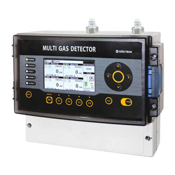
[Figure 1. GTM-1000 Gas Detector] 2. Structure 2.1. System Configuration The GTM-1000 gas detector is a non-explosion-proof product. The gas value is detected by installing a sampling tube in a place where gas leakage is expected or directly inhaling the measured gas, and the detected gas value is displayed on the screen in real time. -
Page 7: How The Sensor Works
Unit3(NDIR gas sensor) In case of GTM-1000, one set of infrared sensor cartridge and up to two non-infrared cartridges can be installed at the same time. With these sensor cartridge combinations, it is possible to measure up to four types of gas and interference gas. The main unit handles various control of the system, measurement signals and communication, alarms, etc., stores the measured gas and... -
Page 8: Electrochemical Method
GTM-1000 Instruction Manual 2.2.2. Electrochemical method The electrochemical gas sensor consists of a detection electrode where oxidation (reduction) reaction occurs, a counter electrode where reduction (oxidation) reaction occurs simultaneously, and a reference electrode to monitor the potential that changes along with the oxidation- reduction reaction and keep the potential constant. -
Page 9: Specification
GTM-1000 Instruction Manual 3. Specification 3.1. Basic Specifications ITEM S P E C I F I C A T I O N Measuring Type Auto Sampling type Measuring Type 4.3” Color TFT Electrochemical / Cartridge Measuring Method Combustible catalytic / Cartridge ... -
Page 10: Environmental Specifications
GTM-1000 Instruction Manual ※ Customer supplied PSU must meet Nominal: requirements IEC1010-1 and CE Marking Absolute max: requirements. Ripple maximum allowed: 1V pk-pk 48 VDC Power-over-Ethernet Input Voltage (POE option) (IEEE 802.3af compliant) Max. wattage: 12W @+24 VDC Wattage Max. current:... -
Page 11: Name And Description Of Each Part
GTM-1000 Instruction Manual Sensor Refer to the sensor specification Pressure Range 90 to 110KPa Max. air velocity 6m/s 4. Name and Description of Each Part 4.1. Components PAGE 11 of 55 Rev 3.2(12.29.2022) - Page 12 GTM-1000 Instruction Manual PAGE 12 of 55 Rev 3.2(12.29.2022)
- Page 13 GTM-1000 Instruction Manual [Figure 3. Components of the GTM-1000] Name Descriptions PAGE 13 of 55 Rev 3.2(12.29.2022)
- Page 14 GTM-1000 Instruction Manual Made of ABS/PC material, fastens the display and protects the circuit Case body from the surrounding environment, and external impact. Made of ABS/PC material, fastens the display and protects the circuit Case cover from the surrounding environment, and external impact.
- Page 15 Channel 4 Relay The connector that connects relay output to the outside when Connector operating in relation to Channel 4. Relay Jumper Setting N.O(Normal Open) and N.C(Normal Close) is possible. [Table 1.Description of the GTM-1000 components] PAGE 15 of 55 Rev 3.2(12.29.2022)
-
Page 16: Configuration Of The Front Display
GTM-1000 Instruction Manual 4.2. Configuration of the Front Display The front display consists of a total of 12 control keys of the gas detector, 5 status LEDs, and a TFT LCD displaying various information. The front configuration is shown in the figure below. -
Page 17: Configuration Of The Device Nameplate
[Figure 5. Configuration of the device nameplate] 4.4. Photo of the Exterior The GTM-1000 gas detector is protected by an ABS/PC material case, and has a TFT LCD window on the front, status LED and 12 control keys for operation control. This product is non-explosive and installed in areas where hazardous gas leakage is expected to detect gas in real time. -
Page 18: Photo Of The Interior
GTM-1000 Instruction Manual 4.5. Photo of the Interior [Figure 7. Photo of the interior] PAGE 18 of 55 Rev 3.2(12.29.2022) -
Page 19: Interior Configuration
GTM-1000 Instruction Manual 4.6. Interior configuration 4.6.1. Main PCB configuration The connector configuration of the Main Board is as follows. DO NOT change the set values arbitrarily. [Figure 8: Main PCB terminal arrangement] Name Description RJ45 Connector CN12 RS232 Connector... -
Page 20: Internal Sensor Catridge Configuration
The sensor cartridge consists of the following and is connected to the communication cable of No. CN15 of the GTM-1000 Main PCB as follows. The cable connection setting of the sensor cartridge must match the channel item in the Configuration setting of the Factory Setting menu. - Page 21 GTM-1000 Instruction Manual For detailed connection and usage of Terminal, refer to the chapter with the detailed description. [Figure 10: Terminal PCB terminal arrangement] Name Description Main Power Switch Relay Selection jumper Power Connector 4-20mA RS485 Gas Channel Alarm Connector...
-
Page 22: Installation
Standard base plate and bracket do not exist due to different installation locations depending on the application. Please contact GASTRON for related data. [Figure 11. General installation configuration] PAGE 22 of 55 Rev 3.2(12.29.2022) -
Page 23: Removing The Terminal Block Cover
GTM-1000 Instruction Manual 5.2. Removing the Terminal Block Cover Loosen the fixing screws on both sides of the terminal block cover at the bottom of the front of the product and separate the cover. The terminal block that connects power and various signals in Terminal PCB appears. - Page 24 GTM-1000 Instruction Manual [Table 6. Description of the power and signal terminal] PAGE 24 of 55 Rev 3.2(12.29.2022)
-
Page 25: Description Of The Channels 1 To 4 Alarm Terminals
GTM-1000 Instruction Manual 5.4. Description of the Channels 1 to 4 Alarm Terminals Alarm settings are basically composed of normal open contacts and can also be used as normal closed contacts by using an internal jumper. PCB Silk 1... -
Page 26: Operation
GTM-1000 Instruction Manual Installation cable length The maximum length between the GTM-1000/2000 and power supply is determined by cable specifications. Maximum installation length = VMAXDROP ÷ IMAX ÷ WIRER/m ÷ 2 VMAXDROP: Maximum Power Loop Voltage Drop (=Power Supply voltage – min operating voltage) ... - Page 27 GTM-1000 Instruction Manual the measurement mode after a certain period of time, and these Timeout settings are set to 30 seconds in the case of Level 1 and Level 2 and 16 minutes in the calibration and test mode. For detailed operation flow, refer to the figure below.
-
Page 28: Initial Operation (Power On) Self-Test Mode
GTM-1000 Instruction Manual Mode Description Remark Enter SELF TEST Mode Performs self-test after initial power on automatically Displays gas measurement values and various statuses Enter Measurement Mode including alarm status automatically Perform Program Bios upgrade via SD card. Enter Program Upgrade Mode... -
Page 29: Gas Measuring Mode
GTM-1000 Instruction Manual When the power is turned on for the first time, the intro screen is displayed for about 3 seconds, and if there is no problem with the device initial setting, it proceeds with the following SELF TEST. - Page 30 GTM-1000 Instruction Manual Device internal judgment delay time in operation Invalid gas signal acquired Displays until the PID signal value exceeds a certain level in the PID ON state Buzzer On status Buzzer Off status In either engineer mode or gas test mode...
-
Page 31: Special Key Function Configuration
After completing the calibration, pressing the ESC key returns to the measurement mode. 6.4.2. Status check mode Function for checking the status of GTM-1000. Possible to enter the status check mode by using the S4 KEY (SPECIAL KEY4). -
Page 32: Setting Mode Configuration
GTM-1000 Instruction Manual Function for checking the calibration range and setting. In the status check mode, it is possible to enter through the S4 KEY (SPECIAL KEY4), LEFT KEY, or RIGHT KEY. ① GAS1, MEA, C4F6, B: 1, I: 0 ... - Page 33 GTM-1000 Instruction Manual [Table 12. Basic configuration of the setting mode Use the MENU key to enter the configured setting mode. After checking the PASSWORD, select the displayed mode as shown in the figure below and press the ENT key to enter the setting mode.
- Page 34 GTM-1000 Instruction Manual If you press other mode entry keys (MENU KEY, S1-4 KEY) in Normal Mode, a window to confirm the password appears. If the user has set the password he or she has set, the set value must be entered to enter the mode.
-
Page 35: Gas Mode Calibration Mode
GTM-1000 Instruction Manual 7.2. Gas Mode Calibration Mode 2-point calibration including zero calibration for sensor zero state calibration and span calibration for sensitivity adjustment of the set measurement range must be performed. For sensor calibration, each sensor's standard calibration gas and sample bag are required, and you must check if the sensor is in normal condition before calibrating the sensor. -
Page 36: Zero Calibration Setting Mode
GTM-1000 Instruction Manual 7.2.1. Zero Calibration Setting Mode It is a calibration work to adjust the zero state of each sensor. If the standby state is clean air, it can be operated without any injecting special gas. If you press the S2 key in the gas selection window, all gases are zero-calibrated. -
Page 37: Program Gas Mode
GTM-1000 Instruction Manual 7.3. Program Gas Mode 7.3.1. Basic Configuration for Program Gas When entering the corresponding mode, select a gas channel that can be set for measurement, and then set related details using the sub-modes shown in the table below. -
Page 38: Setting The Setting Sub Mode (Within The Program Gas Mode)
GTM-1000 Instruction Manual 7.3.2. Setting the Setting Sub Mode (Within the Program Gas Mode) Unit indicates the concentration unit of Gas displayed on the Display. Dot selects the decimal point of currently measured gas. High-Scale selects the maximum value of currently ... -
Page 39: Setting The Sensor Sub Mode (Within The Program Gas Mode)
GTM-1000 Instruction Manual 7.3.4. Setting the Sensor Sub Mode (Within the Program Gas Mode) Type indicates the gas measurement method. Direction indicates whether the sensor data decreases or increases when measuring gas. Sen M/T Ctrl. can fix the sensor output value. -
Page 40: Alarm Mode
GTM-1000 Instruction Manual 7.4. Alarm Mode 7.4.1. Basic Configuration of the Alarm Mode When entering the corresponding mode, after selecting a gas channel for which an alarm can be set, set alarm-related details using the sub-modes shown in the table below. -
Page 41: Setting The Gas Channel Fault (Within The Alarm Mode)
GTM-1000 Instruction Manual Alarm2 can be set the same as Alarm1. 7.4.3. Setting the Gas Channel Fault (within the Alarm Mode) Relay Operate sets the relay to Energized or De- Energized when a Fault Alarm is triggered. Relay output sets the relay to ON or OFF when an alarm ... -
Page 42: Setting The Event Mode
GTM-1000 Instruction Manual 7.5. Setting the Event Mode Depending on the sensor operation status, events like the table below are saved in the internal memory. When saved, the event occurrence time and information are saved simultaneously, and can be checked in the corresponding mode. - Page 43 GTM-1000 Instruction Manual Gas Log Menu During device operation, all measured values of the measured gas channels are saved to the detector's internal memory. The saved value can be recorded for up to 90 days, and if the stored gas value exceeds 90 days, it is overwritten in the order of the latest saved date.
-
Page 44: Troubleshooting
GTM-1000 Instruction Manual 8. Troubleshooting CAUTION: GASTRON or a GASTRON-certified technician must repair component or physical failures. 8.1. Fault List Fault Description & Condition Cause When the sensor is not installed on 1) Bad cartridge unit cable connection E-10... -
Page 45: Recovery List
GTM-1000 Instruction Manual Abnormal IR sensor source In case of less than IR sensor module source E-40 detected voltage standard. Abnormal IR sensor VPP output In case the IR sensor module output voltage is E-41 value detected below the standard... -
Page 46: Interface Configuration
GTM-1000 Instruction Manual Abnormal internal setting value 1) Check the main body setting value 2) Initializing and resetting the body memory 3) Replace the set when the same problem occurs Cartridge unit sensor error Replace the cartridge unit gas sensor... -
Page 47: Modbus Rs485 Register Map
GTM-1000 Instruction Manual Baud rate: 9600 bps Data bits: 8bits Stop bit: 1bits Parity: Even Slave address setting: configured separately for each channel For other details, refer to www.modbus.org 9.1.2. MODBUS RS485 Register map... -
Page 48: Modbus Tcp
GTM-1000 Instruction Manual 9.2. MODBUS TCP 9.2.1. Interface setting MODBUS Port Number 502 For other details, refer to www.modbus.org 9.2.2. MODBUS TCP/IP Register map Category Address Bits Description BIT0 Self Test Mode BIT1 Warm up BIT2 Normal(Measure) Mode... - Page 49 GTM-1000 Instruction Manual Gas Concentration in floating point format word 2 of 2 gas readings 40005 BIT0-15 40024 BIT0-15 Same as above 40025 BIT0-15 Same as above 40044 BIT0-15 Same as above 40045 BIT0-15 Same as above 40064 BIT0-15 Same as above...
- Page 50 GTM-1000 Instruction Manual 40075 BIT0-15 Same as above BIT0-7 Reserved 40016 BIT8-15 Reserved BIT0-7 Reserved 40017 BIT8-15 Reserved BIT0-7 Reserved 40018 BIT8-15 Reserved BIT0-7 Reserved 40019 BIT8-15 Reserved BIT0-7 Reserved 40020 BIT8-15 Reserved BIT0-7 Reserved 40036 BIT8-15 Reserved BIT0-7 Reserved...
- Page 51 GTM-1000 Instruction Manual Reserved 40090 BIT0-15 Reserved BIT0-7 Detector Serial Number 1 of Low byte 40091 BIT8-15 Detector Serial Number 1 of High byte BIT0-7 Detector Serial Number 2 of Low byte 40092 BIT8-15 Detector Serial Number 2 of High byte...
-
Page 52: Outline Drawings And Dimensions
GTM-1000 Instruction Manual 10. Outline Drawings and Dimensions [Figure 16. Outline Drawings and Dimension 1] [Figure 17. Outline Drawings and Dimension2] PAGE 52 of 55 Rev 3.2(12.29.2022) - Page 53 GTM-1000 Instruction Manual [Figure 18. Outline Drawings and Dimension 3] [Figure 19. Outline Drawings and Dimension 4] PAGE 53 of 55 Rev 3.2(12.29.2022)
- Page 54 1000 ppm 500 ppm 1500 ppm 150 ppm 50 ppm 25 ppm 75 ppm [Figure 20: GTM-1000 A/B Front] [Figure 21: GTM-1000 C/D Front] [Figure 22: GTM-1000 E/F Front] [Figure 23: GTM-1000 G Front] PAGE 54 of 55 Rev 3.2(12.29.2022)
-
Page 55: Revision History
GTM-1000 Instruction Manual 12. Revision History Version Contents Date First revision 02.09.2015 Communication interface (analog, RS485) added 02.03.2016 Fault Code added 02.26.2016 Fault Code, Communication Interface (TCP MODBUS) 03.17.2016 added Font changed, ICON description added 08.26.2016 Factory Manual separated 09.30.2016 Modbus TCP Address added 06.12.2017...
Need help?
Do you have a question about the GTM-1000 and is the answer not in the manual?
Questions and answers