Table of Contents
Advertisement
Advertisement
Table of Contents

Subscribe to Our Youtube Channel
Related Manuals for Abilica XC 2700 MILL V4


Summary of Contents for Abilica XC 2700 MILL V4
- Page 1 ABILICA XC 2700 MILL USER’S MANUAL...
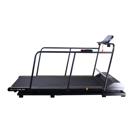
- Page 2 PRODUCT OVERVIEW Console Safety Key Bottle holder Left Handrail Front handrail Motor cover Quick switch Front frame Front pedestal 38 Roller Running belt Right handrail Side rail Back base frame End cap Back main frame...
- Page 3 HARDWARE Note: Some bolts may be pre-installed. Illustrasjon Engelsk navn Ant. Hex round head bolt M8*20 mm Hex round head bolt M8*60 mm Round hex bolt M8*50 mm Round hex bolt M8*30 mm Cross bolt ST4.2*16mm Small Curved Washer M8 Large Curved Washer M8 Flat washer M8 Spring washer M8...
- Page 4 ASSEMBLY PARTS Main frame 1pc A3L Left handrail 1pc A3R Right handrail 1pc C13 Safety Key 1pc A4 Front handrail 1pc B18 Silica gel 1pc B16 Water bottle holder C15 Power cable 1pc 2pcs B1 console 1pc B2 Plug 8pcs...
- Page 5 ASSEMBLY INSTRUCTIONS Remove all parts from packaging before you start assembling. STEP 1 Tilt the wooden case to upright position.
- Page 6 STEP 2 You will find two transport wheels (E13) with brakes (E14) underneath the wooden case. The breaks must be released before moving the case.
- Page 7 STEP 3 After moving the case to the desired position, lay it down as per the illustration. Cut the strap (E15), and remove connecting pads (E16/E18) to remove the wooden case.
- Page 8 STEP 4 Remove and save the fixing bracket (E2), nylon lock nut M8 (E4), transport wheel (E1) and round hex bolt M8*85 (E3) from the wooden case. Note: Save the transport wheels (E1/E13), fixing bracket (E2), nylon lock nut M8 (E4), round hex bolt M8*85 (E3).
- Page 9 STEP 5 Remove the hex round bolt M8*40 (E7), hex round head bolt M8*95 (E11), washer M8 (E8), flat washer M8 (E9) and nut M8 (E10) from upper/lower foot frame (E5/E6), and lift out the main frame.
- Page 10 STEP 6 Connect the left bar (A3L) to the main frame (A1a/b) using hex round head bolts M8*20mm (D31), spring washers M8 (D25) and flat washers M8 (D23). Attach the right bar (A3R) to the main frame the same way. Note: start all bolts before you tighten them.
- Page 11 STEP 7 Attach plugs (B2) to the bottom of left and right bars (A3L/R).
- Page 12 STEP 8 Connect the lower wire’s white connector (C17) to the middle wire’s white connector (C18). STEP 9 Connect the quick switch’s back wire’s black connector (41) to the quick switch’s middle wire’s black connector (C42) and the middle wire’s black connector (C18). STEP 10 Attach the front handrail (A4) to the left and right handrails (A3L/R) using hex bolt M8*50mm (D6), small curved washer M8 (D66) and cap nut (D15).
- Page 13 STEP 11 Attach the 38 roller (C39) to left and right bar (A3L/R) using hex round head bolt M8*60mm (D33), spring washer M8 (D25) and flat washer M8 (D23).
- Page 14 STEP 12 Attach the iron fixing plate (A37) to the front handrail (A4) using round hex bolt M8*20mm (D31) and large curved washer (D67). STEP 13 Guide the emergency switch’s upper wire’s black connector (C43) and the console’s upper wire’s white connector (C16) through the hole in the iron fixing plate (A11).
- Page 15 STEP 14 Attach the console (B1) to the iron fixing plate (A11) using the cross bolt ST4.2*16mm (D52).
- Page 16 STEP 15 Attach bottle holders (B16), safety key (C13) and power cable (C15). Assembly is completed.
- Page 17 TREADMILL TRANSPORT WHEEL ASSEMBLY Transport wheel assembly: Should you need to move the treadmill, it can be moved more easily by attaching the wheels that came with the wooden case. Place the fixing bracket (E2) onto upper and lower foot (E6/E5), and attach the transport wheels (E1/E13) to the fixing bracket using hex round head bolt M8*20mm (E12) and nylon lock nut M8 (E4).
- Page 18 THE TREADMILL MUST BE LUBRICATED BEFORE USE Lubrication Apply 10 ml of the the included oil on the sponge end of the included lubrication stick. Insert the stick underneath the running belt with the oily sponge facing down towards the wooden board. Start by the motor hood and run the stick in a zigzag pattern halfway down the deck.
- Page 19 CONSOLE POSITION CHANGE STEP 1 Remove the console (B1) and the adjustment guide (A12) by unscrewing the scoket head cap bolt M8x20 (D31), large curved washer M8 (D67), Socket head cap bolt M6x16 (D5), flat washer M6 (D22), spring washer M6 (D11) as shown on the illustration.
- Page 20 STEP 2 Place the console (B1) and adjustment guide (A12) on the right handrail (A3R) and attach using socket head cap bolt M8x20 (D31), large curved washer M8 (D67), socket head cap bolt M6x16 (D5), flat washer M6 (D22) and spring washer M6 (D11) as shown on the illustration.
- Page 21 CONSOLE 1.1 DISPLAY 1.2. Start Manual mode will start after a 5 second countdown. 1.3 Program 3 countdown modes / 9 pre-set programs / 3 modes / 3 user programs. 1.4. Safety key "---" Should the safety key be removed from the treadmill, the screen will show the message before the console audio alerts and shuts down.
- Page 22 1.5.1. Start/Stop “START” Push button to start running belt. Speed is set to 1.0. “STOP” Push button to stop running belt. 1.5.2 Program Push button repeatedly to choose desired workout program. Choose between manual mode, pre-set programs P0 to P9, user progrms U1 to U3, three countdown modes, or the fat burn program. Standard speed is set at 1.0 kph, and max speed is 30.0 kph.
- Page 23 1.6. Display functions 1.6.1 SPEED Displays running speed. 1.6.2 TIME Displays running time or how much time is left. 1.6.3 DISTANCE Displays total running distance, or how many kilometres are left. 1.6.4 CALORIE Displays calories burned, or how many calories are left to burn. 1.6.5 INCLINE Displays incline level.
- Page 24 1.8 PROGRAM EXERCISE CHART SET TIME / 16= EVERY GRADE TIME TIME MODE SPEED 10.5 11.5 12.5 13.5 14.5 15.5 16.5 17.5 (16Min) INCLINE SPEED (48Min) INCLINE SPEED (48Min) INCLINE SPEED (32Min) INCLINE SPEED 10.5 11.5 12.5 13.5 14.5 15.5 (16Min) INCLINE SPEED...
- Page 25 1.10 Countdown parametres Standard value, time: 30:00 minutes 5:00 – 99:00 minutes Range: Step: 1:00 Standard value, calories: 50 therm 10 – 990 therm Range: Step: Standard value, distance: 1.0 km 0.5 – 99.9 km Range: Step: The screen will cycle through the data in the following order: MANUAL MODE, TIME, DISTANCE, CALORIES 1.11 Body tester (FAT) After switching on the console, push the PROGRAM button repeatedly to enter the FAT body test.
- Page 26 1.12 Others 1.12.1 When the countdown is over, the message END will be shown on the display. The console will then audibly alert you before the treadmill stops. The manual mode will then automatically be selected. 1.12.2 If you choose values from a set range, you can proceed from the highest value back to the lowest by pushing (+).
- Page 27 Programs Note: All programs are installed to start interval from LEVEL 1 (Grade time). This means that warm-up and cool-down is not included in the main program, and that it is the user’s own responsibility to adjust proper warm-ups and cool-downs in manual mode. RUN1 –...
- Page 28 XCDP1 – POLING INTERVAL – PROFILE Progressive interval training for poling on roller skis. 8 min pull, 2 min pause, 4 min pull, 2 min pause, 4 min pull, 2 min pause, 4 min pull, 2 min pause, 4 min pull, 2 min pause. The pulls are carried out at a 4% incline. The breaks are carried out in the same incline with a light load (speed).
- Page 29 Electrical safety If an overvoltage has occurred, the blue square button (1) will pop out and the power switch (2) will turn off. The blue button must be pressed before you can turn on the power switch again.
- Page 30 MAINTENANCE NOTE: Make sure the electrical outlet is unplugged before cleaning and / or maintaining the product. CLEAN: Regular cleaning will extend the lifespan of the product. Clean the appliance by keeping it free of dust. Be sure to wash the visible parts of the platform on each side of the treadmill, and on the foot rails.
- Page 31 Part Recommended maintenance How often? Cleaning Lubrication Display Clean with a soft, clean and moist cloth. After use Frame Clean with a soft, clean and moist cloth. After use Water Running belt Clean with a soft, clean and moist cloth. Weekly Clean with a soft, clean and moist cloth.
- Page 32 EXPLODED DRAWING...
- Page 33 PART LIST A. Welded parts Description Description Front Base Frame L-shaped tablet Back Base Frame Motor Upper Cover Front Main Frame Incline Shaft Back Main Frame Left End Cap A10L Left Handrail Right End Cap A10R Right Handrail Iron Fixed Plate Front Handrail Adjustment Guide Incline Frame...
- Page 34 C. Electrical parts Description Description Running Belt Brake Rear Roller AC Motor Front Roller Inverter Running Board Single Cord (Blue) 300 Motor Belt Single Cord (Brown) 150 Power switch Single Cord (Blue) 150 Incline Motor Single Cord Safety Key Outlet Single Cord (Brown) 300 38 Roller set Power Cable...
- Page 35 D. Hardware Description Description Screw Driver/Wrench 13-15-17 Spring Washer M5 Allen Wrench T6 Spring Washer M8 Socket Head Cap Bolt Allen Wrench T5 M8X20 Socket Head Cap Bolt Socket Head Cap Bolt M10X35 M8X60 Countersunk Head Hex Bolt Socket Head Cap Bolt M6X16 M6X35 Countersunk Head Hex Bolt Round Head Hex Bolt M8X50...
- Page 36 Error codes Error Code Description Solutions Communication 1. Check if computer is connected to inverter with correct wires, check connector, error between check if wire is damaged, or unplug and re-connect Inverter and console 2. Replace inverter and test 3. Replace computer and test Inverter too hot 1.
- Page 37 IMPORTANT REGARDING SERVICE In the event of problems of any kind, please contact Mylna Service. We would like you to contact us before contacting the store so we can offer you the best possible help. Visit our website - here you will find information about the products, user www.mylnasport.no manuals, a contact form to get in touch with us and possibility to order spare parts.
Need help?
Do you have a question about the XC 2700 MILL V4 and is the answer not in the manual?
Questions and answers