Table of Contents
Advertisement
Quick Links
Advertisement
Table of Contents

Subscribe to Our Youtube Channel
Related Manuals for sauter TN-EE


Summary of Contents for sauter TN-EE
- Page 1 Sauter GmbH Ziegelei 1 Phone : +49-[0]7433- 9933-0 D-72336 Balingen Fax: +49-[0]7433-9933-149 e-mail: info@kern-sohn.com Internet: www.sauter.eu Instruction Manual Multi-Mode Ultrasonic Material Thickness Gauge SAUTER TN-EE Version 2.0 04/2020 PROFESSIONAL MEASURING TN_EE-BA-e-2020...
-
Page 2: Table Of Contents
Material Thickness Gauge Congratulations on the purchase of a multi-mode material thickness gauge from SAUTER. We hope you will enjoy your quality measuring instrument with its wide range of functions. Please do not hesitate to contact us if you have any questions, requests or suggestions. -
Page 3: General Information
1. General information The Model TN-EE is a universal ultrasonic material thickness gauge. The device works according to the same measuring principle as SONAR gauges and is used to measure the thickness of various materials with a measuring accuracy of up to 0.1/0.01mm. -
Page 4: Measuring Principle
1.3 Measuring principle The Ultrasonic Digital Material Thickness Gauge measures the thickness of a part or structure by accurately measuring the time taken for a short ultrasonic pulse to pass through the thickness of a material, controlled by a transducer, then reflected from the back or inner surface and returned to the transducer. -
Page 5: Control Panel And Display Layout
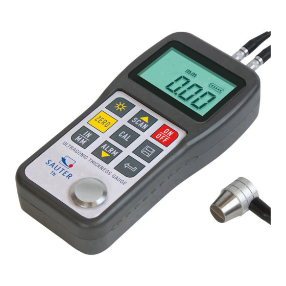
2. Control panel and display layout ULTRASONIC THICKNESS GAUGE POWER: 2 X 1.5V 1 device main part 2 Keypad LCD display Pulse encoder socket 5 Radiation receiver socket Zero plate PC connection socket Label (on the back) Battery cover 10 US measuring probe Explanation: 1. -
Page 6: Explanation Of The Key Symbols
2.1 Explanation of the key symbols Switching on/off Calibration Sound- speed Background lighting Enter key On/ Off Button for Plus; Zero- scan mode position On/ Off Button for Minus; Changing the units pulse-echo switch u. Echo-Echo Mode Save data o. delete 3. - Page 7 So, it might seem, it would be better to use a low frequency probe in any case, but these are less alignable (bundled) than those with high frequencies. Consequently, a high-frequency transducer would be the better choice for detecting small depressions or impurities in the material.
-
Page 8: Conditions And Preparations For Surfaces
The upper figure shows the bottom view of a typical sound generator. The two half circles are visible, visibly divided in the middle. One of the semicircles directs the ultrasound into the material to be measured and the other directs the echo back to the transducer. -
Page 9: Mode Of Operation
4. Mode of operation 4.1 Switching on and off The device is switched on by pressing the key. After switching on, a short test of the display is first carried out by switching on all display segments. After 1s the current setting of the sound velocity and, if necessary, readiness for measurement are displayed. -
Page 10: Zero Calibration
4.3 Zero calibration Important! The zero calibration function is only accessible in the 'Pulse-Echo' measuring mode. To carry out the zero setting, press the key. This is done in almost the same way as a mechanical micrometer is zeroed. If the instrument is not correctly zeroed, all measurements made will be incorrectly zeroed by this incorrect base value. - Page 11 material sound velocity" and will certainly not be the same as the actual material to be measured. 4.4.1 Calibration with known material thickness Note: This procedure requires a sample of the material to be measured, its exact thickness, which has been measured in some way before. 1.
-
Page 12: Perform Measurements
4.4.3 Two-point calibration This procedure assumes that the user has two known material thickness points of the test material and that these are representative for the measuring range. 1. The zero setting is made 2. Coupling agent is applied to the material sample. 3. -
Page 13: Scan Mode (Ultrasound Image Mode)
Note: Sometimes a thin film of the coupling agent is drawn between the US probe and the material surface when the probe is lifted off. In this case, it is possible that a measurement is made through this film, which then turns out to be larger or smaller than it should. - Page 14 1. Press the key to activate the data collection function and to read the current file name and the total number of all data records in the file. 2. Use the and keys to set the desired file as the current one. This program can be exited at any time with the key.
-
Page 15: El Backlight
4.9.3 Entering/deleting stored data records This function allows the user to enter or delete a data record in a desired, previously saved file. The following steps have to be taken: 1. Press the key to activate the measurement data acquisition function and to read the current file name and the total number of all data sets in the file. -
Page 16: Maintenance
5. Maintenance If you experience any unusual problems with your US thickness gauge, please do not repair, replace or disassemble it at your own risk. In such a case, please contact us by e-mail or telephone to discuss the further procedure with the service department. We will then carry out the maintenance as soon as possible. - Page 17 example of this is a pipe made of mild steel with a layer about 0.6 mm thick. The speed of sound propagation for the pipe is 5920 m/s, and for the paint layer 2300 m/s. If the gauge is set to measure the thickness of a mild steel pipe and then the measurement is made over both materials, the thickness of the layer will be 2.5 times greater than it actually is due to differences in the speed of sound propagation.
Need help?
Do you have a question about the TN-EE and is the answer not in the manual?
Questions and answers