Table of Contents
Advertisement
Quick Links
Advertisement
Table of Contents

Related Manuals for sauter HO Series


Summary of Contents for sauter HO Series
- Page 1 Sauter GmbH Ziegelei 1 Phone : +49-[0]7433- 9933-0 D-72336 Balingen Fax: +49-[0]7433-9933-149 e-mail: info@kern-sohn.com Internet: www.sauter.eu Instruction manual ultrasonic hardness tester SAUTER HO Version 2.0 03/2020 PROFESSIONAL MEASURING HO-BA-e-2020...
-
Page 2: Table Of Contents
SAUTER HO V. 2.0 08/2020 Instruction manual ultrasonic hardness tester Thank you for purchasing the digital ultrasonic hardness tester from SAUTER. We hope you will be very satisfied with the high quality of the hardness tester and its extensive functionality. -
Page 3: Safety And Liability
1 Safety and liability These operating instructions contain important information about safe handling and maintenance of your new device. Before using the appliance for the first time, please read these operating instructions completely and carefully. Please keep the manual in a safe place for future reference. 1.1 Safety Instructions Your device is a high-precision instrument;... -
Page 4: Specification
considerable damage to the surface of the test specimen. The Vickers method uses an optical measurement, but a problem-free and correct measurement requires extensive expertise. Furthermore, there is no possibility to test a test piece of greater weight or solid parts for hardness. The ultrasonic hardness tester is based on the ultrasonic contact impedance method for performing comparable hardness tests on test specimens. -
Page 5: Use
2.3 Use * Hardness measurement of flange edge and flanks of gears, moulds, sheet metal, surface-hardened cutting edges as well as tooth grooves and conical parts * Hardness measurement of axles, thin-walled tubes and containers * Hardness measurement of wheels and rotor turbines * Hardness measurement of rotor blades * Hardness measurement of welded parts * Measurement of certain opening depths of incisions, radii of convex marks, irregular... -
Page 6: Structure And Function
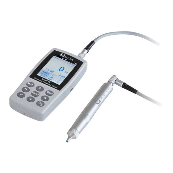
3 Structure and function 3.1 Basic structure and functionality Front and rear view of the ultrasonic hardness tester HO Fig. 1 The main unit is connected by means of an 8-pin data cable and an ultrasonic sensor (see fig. 1.1). The function of the ultrasonic hardness tester is based on the ultrasonic contact impedance method as well as on the modulus of elasticity . -
Page 7: Ultrasonic Sensor
3.2 Ultrasonic sensor 3.2.1 Design of the manual sensor 8-pin female connector Handle position Diamond indenters 3.2.2 Technical data of the manual sensor Type of sensor HO-A01 HO-A02 HO-A13 HO-A14 Available as Accessories Accessories Accessories Accessories 100N Test force 10 N 20 N 22 mm 22 mm... - Page 8 3.2.3 Indenter and impression The ultrasonic penetrator is a diamond penetrator of 136 °. Below is an image of the impression in prism form on the test piece, the size of the impression varying according to the material of the test piece. The shape of the impression is the same as the Vickers method and would require a strong microscope for observation.
-
Page 9: Technical Properties
4 Technical properties 4.1 Technical data Measuring ranges: HO-A03 20,3~68 41~100 61~85,6 80~1599 76~618 Supported and HRC, HV, HBS, HBW, HK, HRA, HRD, HR15N, displayed HR30N, HR45N, HS, HRF, HR15T, HR30T, HR45T, hardness scales Tensile strength 255~2180 N/mm² Battery: Voltage 4,2V Capacity 4800mAh... -
Page 10: Safety Instructions For Handling
5 Safety instructions for handling 5.1 Preparation and control 5.1.1 Requirements concerning test pieces Minimum thickness The ultrasonic hardness tester uses a Vickers diamond indenter, so the Vickers hardness calculation formula is also used in the ultrasonic hardness tester. Thin layers or top coats of base material must have a minimum thickness (t). - Page 11 Material thickness of the test object, test load and hardness value (HV 0.2 up to HV 100) Important! According to the ultrasonic contact impedance method (UCI method), the sensor must come into contact with the test piece, then it starts to oscillate and the hardness value is determined.
-
Page 12: Measurement
Roughness of the test piece surface The applied test load (i.e. the selected UCI sensor) must be designed not only for the specific application, but also for surface quality and roughness of the fabric. For smooth and homogeneous surfaces a low test load can be applied, for surfaces of greater roughness and coarseness the highest possible test load should be applied. - Page 13 If this is the case, the user can perform the calibration himself. The HO device supports hand-held and motorized sensors, available in the SAUTER range. The sensor type must be set before measurement.
- Page 14 5.2.2 Measurement with a motorized sensor Select [Menu]-[Select probe]-[Motorized probe]- Select [Motorized probe]. After correct connection, place the sensor vertically on the test sample, then press the red button on the top of the sensor. An AUTO test is performed. After 2s, the main unit triggers an acoustic signal, which means that the test load has expired.
- Page 15 The result of the measurement is stored under [Memory settings]→ [Data overview], where all test results can be selected using the arrow keys [↑] and [↓]. Single test mode: After the acoustic signal, the display shows the message "Ready", which means that the first measurement has been completed. The test result is stored in [Memory Settings]→...
- Page 16 Group mode: After the acoustic signal, the display shows the message "Ready", which means that the 1st measurement has been completed. Then repeat the measurement 4 times. After the 5th measurement, two acoustic signals are triggered by the main unit and the display shows the message "Complete" in the upper left corner, which means that 5 measurements have been performed in this group.
-
Page 17: Special Precautions
6 Special precautions Before changing the sensor, switch off the power supply to the main unit, then: hold the sensor perpendicular to the surface of the test sample during measurement. If the device is not used for a longer period of time, it must be recharged before being used again. -
Page 18: Handling
7 Handling 7.1 Masks and buttons 7.1.1 Menu masks Sensor type Status display Test standard Test status Test result Hardness Conversion Test time Statistics The menu masks contain status display, model info, calibration data, test display, result list and info list for test results as shown in Fig. 6-3. * Status display: model, buzzer, system time, battery. - Page 19 7.1.2 Control buttons MAT: • Start of the calibration process in the calibration mask ; selection of the calibration group in the calibration mask ; abbreviation for the calibration mask in the main mask • Move up or increase UNIT: •...
-
Page 20: Test Settings
• Press and hold - Switch to sleep mode 7.2 Test settings Press the [MENU] keys and select the [Test Setup] sub-category to display the Test Settings screen. Hardness scale: Select the [Hardness scale] tab to select the desired hardness scale. -
Page 21: System Settings
7.3 System settings Press the [MENU] keys and select the [Settings] submenu to display the Test Settings screen. Sound: Select the [Key Tone] tab and use the [↑] and [↓] keys to select the desired ON/OFF option, setting "OFF" will turn off any sound. Battery Management: Select the [Battery Management] tab and select the desired ON/OFF option with the [↑] [↓] keys. -
Page 22: Memory Settings
7.4 Memory settings Press the [MENU] keys and select the [Save Settings] submenu to display the Memory Settings screen. Auto Save: Select the [Auto Save] section and select ON/OFF with the [↑] [↓] keys; with the ON option, measured data are automatically saved. Result display: The [Display Results] tab can be accessed in two ways: - in the main mask press the keys [↑] or [↓];... -
Page 23: Print Settings
PC Connected : Select the [Connected] tab and use [↑] [↓] to switch the mode on or off. The test results are sent to the computer via the hyperterminals. Partial deletion: Select the [Delete Parts] tab . To delete selected test results, press the [ ENTER] key to select records to delete, then press the [UNIT] key to delete them. -
Page 24: Calibration
7.6 Calibration Press the [MENU] key and select [Calibration Option] to display the Memory Settings screen. Perform calibration. Select the [Perform Calibration] tab and use the [↑] keys to select [↓], then press the [MAT] key to confirm (calibration must be performed before measurement). - Page 25 Hold the sensor and slowly lower it vertically onto the hardness comparison plate when the display shows 'Test - Ready'. If the sensor is pressed during testing when an acoustic signal is triggered, this means that the discharge process has been initiated. The sensor must then not be moved until the display shows the message 'Ready'.
-
Page 26: Permissible Deviation And Repeatability
Remarks : • In the calibration screen, first press the [MAT] key, then place the sensor vertically on the hardness comparison plate, and if there is no reaction, leave the sensor in place and press the [MAT] key again. Then perform 6 measurements. •... -
Page 27: Battery
7.8 Battery A rechargeable battery is mounted in the main unit (4.2 V, 4800 mAh). When the battery is empty, a symbol appears in the upper right corner to prompt you to charge the battery ( ). Connect the mains adapter to the socket on the unit and the plug to the 220 V mains. -
Page 28: Warranty
9 Warranty 10.1 The warranty for the display unit is 2 years and covers only qualitative defects. The accessories are excluded from the warranty protection. Please check the packing list of the unit. 10.2 If the unit needs to be repaired, please enclose a copy of the invoice with the unit.
Need help?
Do you have a question about the HO Series and is the answer not in the manual?
Questions and answers