Table of Contents
Advertisement
Quick Links
Advertisement
Table of Contents

Related Manuals for sauter SAUTER HMO


Summary of Contents for sauter SAUTER HMO
- Page 1 Sauter GmbH Ziegelei 1 Tel.: +49-[0]7433- 9933-199 D-72336 Balingen Fax: +49-[0]7433-9933-149 E-Mail: info@sauter.eu Internet: www.sauter.eu Instruction Manual Mobile digital Leeb Impact Hardness Tester SAUTER HMO Version 1.4 01/2018 PROFESSIONAL MEASURING HMO-BA-e-1814...
-
Page 2: Table Of Contents
Instruction Manual Mobile digital Leeb Impact Hardness Tester Thank you for buying this digital SAUTER Leeb impact hardness tester. We hope you are pleased with your high quality instrument and with its big functional range. If you have any queries, wishes or helpful suggestions, do not hesitate to call our service number. -
Page 3: Introduction
1 Introduction 1.1 Principle The tester measuring principle is physically a rather simple one for this dynamic hardness tester. An impact body with a hard metal test tip is propelled by a spring force against the surface of the test piece. Surface deformation takes place, when the impact body hits the test surface, which will result in a loss of kinetic energy. -
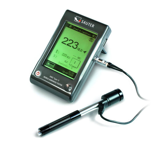
Page 4: Display
Impact Device (type D) The display unit can be connected to almost every type of Leeb impact device. It can identify them automatically. D type (standard sensor) is shown in Fig.1-3,please see the others in appendix (chapter 5) for further description. 1.2.2 Display The hardness tester has a big LCD with touchpad. -
Page 5: Application Range
• Storage Temperature: -10°C~+60°C (14°F~140°F) • Dimension: 130 x 87 x 28 mm • Weight: 240g 1.4 Application Range • Good for all metals, ideal for production level testing • Best suited for on-site testing of heavy, big or already installed parts •... - Page 6 Fig.2-2 In the process of the test surface preparation, influences of cold and heat should be avoided on the specimen’s surface. Test surface should be flat with metallic luster, there may be no oxid layer and other kinds of impurities on it. The roughness of test surface The specimen must be of sufficient mass and rigidity.
-
Page 7: Testing Procedure
2.3 Testing procedure Loading Loading Locating Simply load the impact device by sliding the loading tube forward. Locating Then place and hold the impact device onto Impacting the surface of the specimen at the desired test point. Impact direction should be vertical Fig 2-5 to the surface of the specimen in a right angle. -
Page 8: Setup
2.5 Print The tester can be linked to a wireless printer to print a report. Place the printer near the tester (within 2 meters), and turn its power on. The test report is shown as Fig 2.7. The specific contents of the report can be setup in Items menu. (See 3.2.2) 3 Setup The tester uses a touch pad, most of common settings can be arranged in the main... -
Page 9: Testing Setup
△ In main interface, touch Menu to enter the menus. In menus: touch“ ”or “ ▽ ” to page up or page down Touch Back in the upper menu, or return to main interface. 3.2.1 Testing Setup 3.2.2 → → Fig. -
Page 10: Printing Setup
❷ The material group must be reset when you ❸ As we all know, the conversion is for set to tensile strength (MPa). reference only. To obtain precise conversions, you will have to do comparison tests. Limit Values The maximum limit and minimum limit of tolerance can be set. -
Page 11: Memory Management
3.2.4 Memory Management You can browse and delete data in memory. The test data saved in memory includes all test information. It can store up to 500 data. When it is full, the new data will squeeze the earliest data. →... -
Page 12: System Setting
See manual of software for details. 3.2.5 System Setting Custom Mate You can customize your conversion tables, and select them in "Material A", "Material B" and "Material C". → You can select the scale and input the Fig. 3-18 conversion table.(Fig.3-19) Auto Print If Auto Print is set to "ON", when the test of a statistic group is finished, the tester will print the... -
Page 13: Calibration
4.3 Calibration Test Calibration It is used to calibrate the tester, in order to → → Fig. 4-1 reduce the error in future. Enter Test Calibration. Select the type of impact device. Then choose a scale you want to calibrate in. If HL is selected, you can enter calibration interface directly. -
Page 14: Appendix
5 Appendix Type DL Type C A-1 Type of Impact Device Surface hardened components, Type D Type DC coatings, thin walled or impact The shorted D, can measure sensitive components into the more narrow space. For in extremely confined The basic type, it is suitable spaces or at the base of for almost all applications. -
Page 15: Scale Range
5.1 Scale Range 5.2 Packing List ❶ Display Unit ❷ Impact Device ❸ Test Block ❼ ❻ ❹ Mini-Printer ❺ Charger ❻ Little Support Ring, ❼ User's Manual ❽ Carrying Case Cleaning Brush ❹ ❺ ❸ ❶ ❷ ❽ Annotation: To have a look at the CE Declaration of Conformity, please click onto the following link: https://www.kern-sohn.com/shop/de/DOWNLOADS/...
Need help?
Do you have a question about the SAUTER HMO and is the answer not in the manual?
Questions and answers