Table of Contents
Advertisement
Quick Links
Advertisement
Table of Contents

Related Manuals for sauter HK-D


Summary of Contents for sauter HK-D
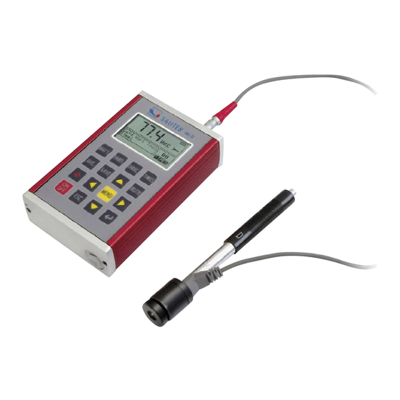
- Page 1 Sauter GmbH Ziegelei 1 Tel: +49-[0]7433- 9933-199 D-72336 Balingen Fax: +49-[0]7433-9933-149 E-Mail: info@sauter.eu Internet: www.sauter.eu Instruction Manual Mobile Leeb Hardness Tester SAUTER HK-D/ HK-DB Version 1.3 07/2017 PROFESSIONAL MEASURING HK-D_HK-DB-BA-e-1713...
-
Page 2: Table Of Contents
Version 1.3 07/2017 Instruction Manual Mobile Leeb Hardness Tester Thank you for buying a digital SAUTER Leeb hardness tester. We hope you are pleased with your high quality instrument and with its big functional range. If you have any queries, wishes or helpful suggestions, do not hesitate to call our service number. - Page 3 6.3.3 Key operation ........................... 15 Menu structure diagram......................16 Measuring condition setting ....................17 6.5.1 Impact direction setting......................18 6.5.2 Mean times setting ........................18 6.5.3 Material setting ......................... 18 6.5.4 Hardness scale setting ......................19 6.5.5 Tolerance limit setting....................... 19 6.5.6 Hardness/σ...
-
Page 4: General Description
Safety Precautions 1. The complete instruments may not be immerged into water either be exposed to rain. This could lead to unpredictable damages. The accumulator or display could be destroyed. 2. If the instrument is not used for a longer period of time, it should be stored cool and dry, the best in its original package. -
Page 5: Testing Range
1.2.2 Testing Range Testing range see table 1 and table 2. Table 1 Hardness Material method D/DC D+15 17.9~ 19.3~ 20.0~ 20.6~68. 68.5 67.9 69.5 59.6~ 47.7~ 37.0~99. 99.6 99.9 59.1~ 85.8 Steel and 127~ 80~ 80~ 90~ cast steel 81~646 80~... -
Page 6: Types And Specification
Table 2 Strength σ Material (MPa) Mild steel 350~522 374~780 High-carbon steel 500~710 737~1670 Cr steel 500~730 707~1829 Cr-V steel 500~750 704~1980 Cr-Ni steel 500~750 763~2007 Cr-Mo steel 500~738 721~1875 Cr-Ni-Mo steel 540~738 844~1933 Cr-Mn-Si steel 500~750 755~1993 Super strength 630~800 1180~2652 steel... - Page 7 Impact device Diameter 20mm 20mm 20mm 30mm Impact device Length 86(147)/ 162mm 141mm 254mm Impact device 75mm Weight 250g Max. hardness 940HV 940HV 1000HV 650HB workpiece Mean roughness 1.6μm 1.6μm 0.4μm 6.3μm workpiece surface of the Min. weight of sample >1.5kg Measure directly Need >5kg...
- Page 8 Indentation 0.35mm 0.35mm 0.35mm Hardn diameter Indentation 10μm 10μm 7μm 800HV depth D+15: General test groove small, light, large, thick, re-entrant thin parts heavy Hole or hol- surface or surface rough sur- low- hard- face steel Available type of impact cylindrical ened layer device...
-
Page 9: Operating Conditions
1.4 Operating conditions Ambient temperature: -10℃~40℃ Relative humidity: ≤90% No vibration, no strong magnetic field and no corrosive medium and heavy dust in ambient environment. Structure features and testing principle 2.1 Structure Features 2.1.1 Hardness Tester 1: Main unit 2: Impact device 2.1.2 Main unit 1: Shell 2: Communication socket... -
Page 10: Non-Conventional Types Of Impact Devices
1: Release button 2: Loading sheath 3: Guide tube 4: Coil part 5: Connection cable 6: Impact body 7: Support ring 2.1.4 Non-conventional types of impact devices D+15 2.2 Testing principle Let an impact body whose weight is definite rush into the surface of sample, the hardness value comes from the rate of rebound velocity and rush velocity at 1mm distance from testing surface. -
Page 11: Dimension, Size And Weight
3.2 Dimension, size and weight 3.2.1 Dimensions: 132×82×33mm (main unit) 3.2.2 Weight: approx. 0.6kg (main unit); Table 5 Type of hardness value of Error of Repeatability of impact standard Leeb displayed displayed value device hardness block value 760±30HLD ±6 HLD 6 HLD 530±40HLD ±10 HLD... -
Page 12: System Setting Of Tester
Work piece supporting —— Support is not necessary for heavy test work pieces —— Work pieces with medium weight must be placed on flat and solid plane, and they must be placed stably without any shaking. Enough thickness of work pieces is necessary, and the min. thickness should comply with the specification in table 3. -
Page 13: Testing
4.2.3 Testing Press down the release button on the top of the impact device to make a test. At this point, the test sample, impact device and the operator are all required to be stable; and the force direction should comply with the axis of the impact device. Five measurements should be carried out per measuring position of test sample. -
Page 14: Special Prompts
400HVHLD expresses that the Vickers hardness value is 400, which changed from Leeb hardness value measured by D type impact device. Note: HL values which measured by various impact devices are various. For example: 700HLD≠700HLC. 5 Special prompts Replacing impact device must be performed under the condition of turn off, otherwise the impact device type cannot be identified automatically, and even it is possible to cause the damage of circuit board of the tester. -
Page 15: Explanation Of The Main Display Interface
The measured values are displayed with big font in this interface, and multiple short- cut key operation functions supplied. 6.3.1 Explanation of the main display interface Battery information: displaying rest capacity when no charging, and displaying charging degree when charging. Impact direction: current impact direction. -
Page 16: Menu Structure Diagram
key to move the cursor to 【YES Press the . Then press the 【ENTER】key to confirm the deletion of the latest single measured value. Press the key to move the cursor to【NO】. Then press the 【ENTER】key to cancel the deletion. Deletion can be also cancelled by pressing the 【ESC】key wherever the cursor is located. -
Page 17: Measuring Condition Setting
The parameter setting and additional function of equipment can both realized by menu operating. At the main display interface, pressing 【MENU】 key to enter the main menu. 6.5 Measuring condition setting When being in main display interface, press【MENU】 key to enter the main menu. Press 【ENTER】... -
Page 18: Impact Direction Setting
3. The symbol ↓ on the left bottom of menu shows the menu is not end, which can be paged down by press 【 】 key; The symbol ↑ on the top of menu shows the menu is not end, which can be paged up by press 【 】. 6.5.1 Impact direction setting Press key to move cursor to the direction which will be set. -
Page 19: Hardness Scale Setting
2. Material should be chosen prior to the hardness scale. 3. The symbol ↓ on the left bottom of menu shows the menu is not end, which can be paged down by press 【 】key; The symbol ↑ on the top of menu shows the menu is not end, which can be paged up by pressing 【... -
Page 20: Print Function
Press 【ENTER】 key to finish the change. Press 【ESC】 key to cancel the change. Note: 1. If the setting exceeds the measuring range, the tester will ask operator to reset. 2. Exchanging will be done automatically if the Min. tolerance limit is more than Max. -
Page 21: Print Memory Value
6.6.2 Print memory value As for 【Print Memory】, the group range is necessary to be selected firstly, and the group range which saved in memory will be displayed at the same time. Press number key to input the value, and the cursor can move in circles to right automatically. -
Page 22: Print All Memory
2. No difference for the sequence to print the starting and ending group, that is to say if 1~5 groups will be printed, the sequence can be set from 1 to 5 or from 5 to 1. 3. Wider the range of groups, shows the nearer the group from current; on the contrary, it will be further. -
Page 23: Deleting Selected Group
6.7.4 Deleting selected group Press 【Delete by No.】 key, an interface including group range to be deleted will be shown. Press number key to input digital value. Press 【Enter】 key to cancel selected group. Press 【Esc】 key to cancel the operation. Note: 1. -
Page 24: System Set
By pressing 【ENTER】 key, cursor will be shown and furthermore details can be viewed. Press 【 】or 【 】 key to select the group in this interface. Press 【ESC】 key to return to the previous viewing interface. Press 【ENTER】 key to view detail information in this group. Press 【... -
Page 25: Lcd Brightness Set
If 【Auto Trans.】 is set to 【On】, the current group data can be output in text for- mat via RS232 after measuring finished and average value displayed. If 【Key Sound】 is set to 【On】, buzzer will send out a short sound with each pressing. -
Page 26: Calibration Of The Tester
Information about the tester and embedded software will be displayed on this inter- face. The software version and embedded software identification are subjected to change due to the upgrading of software without notifying in advance. 6.11 Calibration of the Tester The tester and impact device must be calibrated with a standard Leeb hardness test block (not included in delivery) prior to the first use, or reusing after a long term idle. -
Page 27: Battery Replacement
In case of too low battery voltage, “Battery Empty!” will be displayed and turn off automatically. 6.14 Battery replacement Battery symbol will flash if battery capacity runs out. At this point, User can re- place the damaged battery according to the following procedures. Turn off the Power of main unit. -
Page 28: Transportation And Storage
9 Transportation and Storage The tester should be stored in room temperature, away from vibration, strong mag- netic field, corrosive medium, dampness and dust. 10 Non-warranty parts 1 Sheath of Main unit 2 Panel 3 Impact body 4 Support ring 5 Sensor cable 6.
Need help?
Do you have a question about the HK-D and is the answer not in the manual?
Questions and answers