
Related Manuals for GF CONTAIN-IT Plus


Summary of Contents for GF CONTAIN-IT Plus
- Page 1 GF Piping Systems Instruction manual Bedienungsanleitung CONTAIN-IT Plus Ball Valve Type 546 CONTAIN-IT Plus Kugelhahn Typ 546...
- Page 2 Betriebsanleitung Inhaltsverzeichnis Deutsch CONTAIN-IT Plus Kugelhahn Typ 546…………………………………………… 3 English CONTAIN-IT Plus Ball Valve Type 546 …….……………………………….. 27...
-
Page 3: Table Of Contents
Bestimmungsgemässe Verwendung Sicherheitshinweise Transport und Lagerung Aufbau und Funktion Aufbau Funktion Installation Vorbereiten Installation Druckprüfung vorbereiten Druckprüfung durchführen Montage CONTAIN-IT Plus Kugelhahn Typ 546 Wartung Ausbau Einbau Nachrüstung von Antrieben Störungsbehebung Ersatzteilliste Zapfen PE-Anschlussstutzen Einschraubteil/ Einlegeteil Kugelhahn Typ 546, Zentralteil 10 Entsorgung 11 EG-Konformitätserklärung... -
Page 4: Originalbetriebsanleitung
Betriebsanleitung Originalbetriebsanleitung Originalbetriebsanleitung Betriebsanleitung beachten Die Betriebsanleitung ist Teil des Produkts und ein wichtiger Baustein im Sicherheitskonzept. Betriebsanleitung lesen und befolgen. Betriebsanleitung stets am Produkt verfügbar halten. Betriebsanleitung an alle nachfolgenden Verwender des Produkts weitergeben. Zu diesem Dokument Warnhinweise In dieser Anleitung werden Warnhinweise verwendet, um Sie vor Tod, Verletzungen oder vor Sachschäden zu warnen. -
Page 5: Weitere Symbole Und Auszeichnungen
Mitgeltende Dokumente Georg Fischer Planungsgrundlagen Industrie Bedienungsanleitung Kugelhahn Typ 546 (GFDO 5684) Diese Unterlagen sind über die Vertretung von GF Piping Systems oder unter www.gfps.com erhältlich. Sicherheit und Verantwortung Bestimmungsgemässe Verwendung Der CONTAIN-IT Plus Kugelhahn Typ 546 ist ausschliesslich dazu bestimmt nach... -
Page 6: Transport Und Lagerung
Betriebsanleitung Transport und Lagerung Personal regelmässig in allen zutreffenden Fragen der örtlich geltenden Vorschriften für Arbeitssicherheit, Umweltschutz vor allem für druckführende Rohrleitungen unterweisen. Betriebsanleitung und die darin enthaltenen Hinweise kennen, verstehen und beachten. Bei jedem Ein- bzw. Ausbau der Doppelrohr-Armatur die Einbaubedingungen sowie die Sicherheits- und Warnbedingungen der mitgeltenden Betriebsanleitung für den Kugelhahn Typ 546 beachten. -
Page 7: Aufbau Und Funktion
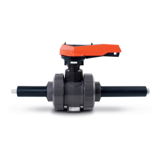
Aufbau und Funktion Betriebsanleitung Aufbau und Funktion Aufbau Abb. 1 Durchgangsbohrung für die Zapfen Leckageüberwachung der Innenleitung Überwurfmutter Schutzgehäuse Distanzhalter Einlegteil Abstützungen PE Schutzgehäuse Einschraubteil Anschluss für ½ Zoll O-Ringe zum Einlegteil / Leckageüberwachung oder PVC- Einschraubteil U ½ Zoll Stopfen Kugelhahn Typ 546 (Zentralteil) O-Ringe zum Zapfen Überwurfmutter Kugelhahn Typ... -
Page 8: Funktion
Doppelrohr-Armaturen von GF Piping Systems werden als einbaufertige Systemeinheit geliefert und analog einem Doppelrohrfitting verarbeitet. Das Prinzip der Doppelrohr-Verbindungstechnik von GF Piping Systems basiert darauf, dass zuerst die Innenleitung nach der von Ihnen gewählten Verbindungstechnik verbunden wird. Folgende Verbindungstechniken und... -
Page 9: Installation
Installation Betriebsanleitung ACHTUNG Sachschaden beim Einbau des Kugelhahns! Inkorrekter Einbau kann zu Problemen bei den Toleranzen führen. Sicherstellen, dass die Verbindung der Rohrenden mit den anderen Rohrleitungsabschnitten erst nach dem Zusammenbau des Kugelhahns erfolgt. Installation WARNUNG Verletzungsgefahr und/ oder Sachschaden beim Ausbau des Handhebels! Durch den Aufbau von Innendruck kann der Austritt des Zapfens zu Verletzungen/ Beschädigungen führen. - Page 10 Betriebsanleitung Installation 3. Sicherstellen, dass Druckklasse, Anschlussart und Anschlussabmessungen den Einsatzbedingungen entsprechen. 4. Kugelhahn erst unmittelbar vor Einbau aus Originalverpackung nehmen. 5. Sicherstellen, dass die Kugelhahnstellung auf „AUF“ ist, siehe Abb. 1 6. Innenrohr des Kugelhahns mit Innenrohr der Doppelrohrleitung verbinden. 7.
- Page 11 Installation Betriebsanleitung Maximale Einschraubtiefe der Schrauben in den Kugelhahn: 10/15 20/25 32/40 Schraube Einschraubtiefe H (mm) ACHTUNG Wird bei Temperaturwechseln die Wärmeausdehnung verhindert, treten Längs- bzw. Biegekräfte auf! Um die Funktionsweise der Armatur nicht zu beeinträchtigen: Sicherstellen, dass Kräfte durch geeignete Festpunkte vor bzw. hinter Armatur aufgenommen werden.
-
Page 12: Druckprüfung Vorbereiten
Betriebsanleitung Installation Druckprüfung vorbereiten 1. Sicherstellen, dass der rote Handhebel parallel zur Hauptleitung steht. Abbildung 1 2. Muttern am Handhebel lösen. 3. Handhebel entfernen. Abbildung 2 4. Überwurfmuttern des Schutzgehäuses beidseitig lösen. 5. Überwurfmuttern und Einlegteil zur Seite schieben. Abbildung 3 6. -
Page 13: Druckprüfung Durchführen
Installation Betriebsanleitung 9. Gehäuse zur Seite des Einlegteils schieben. Der Kugelhahn ist nun zugänglich Abbildung 6 Druckprüfung durchführen WARNUNG Verletzungsgefahr und/ oder Sachschaden beim Drucktest! Der Einsatz von gefährliche Medien zum Drucktest kann ein Risiko für die Anlage bedeuten und im Falle einer Leckage Schäden oder Verletzungen zur Folge haben. -
Page 14: Montage Contain-It Plus Kugelhahn Typ 546
Betriebsanleitung Installation Montage CONTAIN-IT Plus Kugelhahn Typ 546 1. Gehäuse über den Kugelhahn schieben. Abbildung 7 2. Zapfen durch die Öffnung des Gehäuses stecken. 3. Dabei die richtige Position des Zapfens beachten, siehe Kontur des Zapfens und des Kugelhahns. Abbildung 8 Abbildung 9 4. - Page 15 Installation Betriebsanleitung 5. Einschraubteil in das Schutzgehäuse (Linksgewinde!) schrauben und mit dem Zapfenschlüssel anziehen. Abbildung 11 6. Einlegteil positionieren und Überwurfmuttern auf beiden Seiten verschrauben. Überwurfmutter mit einem geeigneten Schlüssel anziehen. Abbildung 12 7. Handhebel auf das Gehäuse montieren. Abbildung 13...
-
Page 16: Wartung
Wartung VORSICHT Materialschaden und/oder Verletzungsgefahr! Bei Austausch dürfen ausschliesslich die für die Armatur vorgesehenen Original-Ersatzteile von GF Piping Systems verwendet werden. Ersatzteile mit den Angaben auf dem Typenschild bestellen. Keine Schmiermittel auf Mineralölbasis oder Vaseline (Petrolatum) verwenden. Für lackstörungsfreie Kugelhähne spezielle Herstellerhinweise beachten. -
Page 17: Ausbau
Polyglykolbasis fetten Wir empfehlen beim Wiedereinbau des Kugelhahns generell neue Dichtungselemente zu verwenden. 2. CONTAIN-IT Plus Kugelhahn Typ 546 in die Innenleitung einsetzen. Dabei beachten, dass sich der Kugelhahn in „offener“ Stellung befindet. 3. Druckprüfung, siehe Kapitel Druckprüfung durchführen 4. -
Page 18: Nachrüstung Von Antrieben
Betriebsanleitung Nachrüstung von Antrieben Nachrüstung von Antrieben Der CONTAIN-IT Plus Kugelhahn Typ 546 kann mit den Antrieben EA11, EA21 und PA21 gemäss nachfolgender Beschreibung aufgerüstet werden. Bitte beachten Sie jeweils auch die Anleitungen der jeweiligen Antriebe. Zur Aufrüstung eines Antriebes benötigen Sie das Adapter Set 700 238 796. Dieses... - Page 19 Nachrüstung von Antrieben Betriebsanleitung 5. Adapterplatte mit vier Senkschrauben an den Antrieb montieren. Abbildung 17 6. Reduzierhülse auf den Zapfen des Kugelhahns setzen. Abbildung 18 7. Antrieb mit der Adapterplatte auf das Anschlussmodul des Kugelhahns montieren. Abbildung 19...
-
Page 20: Störungsbehebung
Betriebsanleitung Störungsbehebung 8. Kugelhahns und Antrieb sind nun betriebsbereit. Abbildung 20 Störungsbehebung Störung Mögliche Ursache Störungsbehebung Rohrleitung und/oder Rohrleitungskräfte Abstützung der Rohrleitung Kugelhahn verformen sind zu hoch verbessern sich bzw. dehnen sich Vorzeitiger Verschleiss Werkstoff sind nicht Geeignete Werkstoffe des Kugelhahns oder genügend beständig auswählen, siehe... - Page 21 Störungsbehebung Betriebsanleitung Mediumsleckage an Überwurfmutter Überwurfmutter nachziehen. Verbindung zwischen nicht korrekt Ventilkörper und angezogen Überwurfmutter Leckage im Sitz / Vorspannung nicht Überwurfmutter korrekt Durchgangsleckage korrekt anziehen. Armatur schwergängig Verschleiss von Funktionsteile wechseln. Kugel und Zapfen Leckage des Steuer- Verschleiss der ...
-
Page 22: 10 Ersatzteilliste
Betriebsanleitung Ersatzteilliste 10 Ersatzteilliste 10.1 Zapfen siehe Kapitel Aufbau, Pos. 3 Dimension Artikelnummer Menge Dimension Beschreibung Kugelhahn d20/50 – d32/50 748 410 103 3.54mm x 29.75mm O-Ring EPDM 749 410 103 3.54mm x 29.75mm O-Ring FPM d40/75 – d63/110 748 410 027 3.54mm x 37.69mm O-Ring EPDM 749 410 027... -
Page 23: Kugelhahn Typ 546, Zentralteil
Ersatzteilliste Betriebsanleitung 10.4 Kugelhahn Typ 546, Zentralteil siehe Kapitel Aufbau, Pos. 9 EPDM Dichtungsset: Dimension Kugelhahn Artikelnummer Beschreibung d20/50 161 486 400 Dichtungsset EPDM bestehend aus: d25/50 161 486 401 2 Hinterlagedichtungen 1 Gehäusedichtung d32/63 161 486 402 2 Anschlussdichtungen d40/75 161 486 403 2 Zapfen O-Ring Dichtungen... -
Page 24: 11 Entsorgung
Vorschriften entsorgen. Sicherheitsdatenblatt konsultieren. eventuelle Medienrückstände im Produkt neutralisieren. Werkstoffe (Kunststoffe, Metalle, usw.) trennen und diese nach den örtlichen Vorschriften entsorgen. Bei Fragen bezüglich der Entsorgung des Produkts wenden Sie sich an Ihre nationale Vertretung von GF Piping Systems. -
Page 25: 12 Eg-Konformitätserklärung
EG-Konformitätserklärung Betriebsanleitung 12 EG-Konformitätserklärung EG-Druckgeräterichtlinie 97/23 EG Der Hersteller Georg Fischer Rohrleitungssysteme AG, 8201 Schaffhausen (Schweiz) erklärt, dass die Kugelhähne des Typs 546 gemäss der harmonisierten Bauart-Norm EN ISO 16135 1. Druckhaltende Ausrüstungsteile im Sinne der EG-Druckgeräterichtlinie 97/23 EG sind und solchen Anforderungen dieser Richtlinie entsprechen, die für Armaturen zutreffen. -
Page 27: Content
Transport and storage Design and function Design Function Installation Preparation Installation Prepare pressure testing Pressure testing the inner pipe Assembling the CONTAIN-IT Plus Ball Valve Type 546 Maintenance Remove Re-install Upgrade with an actuator Troubleshooting list Spare parts list Stem PE-connecting adaptor... -
Page 28: Original Instruction Manual
Instruction Manual Original instruction manual Original instruction manual Observe instruction manual The instruction manual is part of the product and an important element within the safety concept. Read and observe instruction manual. Always have instruction manual available at the product. ... -
Page 29: Further Symbols And Labels
Safety and responsibility Intended use CONTAIN-IT Plus Ball Valves Type 546 are intended exclusively for shutting off and conveying media in the allowable pressure and temperature range or for controlling flow in piping systems into which they have been installed. The valve is intended to be used within the chemical resistance of the valve and all components involved. -
Page 30: Transport And Storage
Instruction Manual Transport and storage Regularly train personnel in all relevant questions regarding locally applicable regulations regarding safety at work, environmental protection especially for pressurised pipes. The personnel is responsible for the following measures: Know, understand and observe the instruction manual and the advices therein. ... -
Page 31: Design And Function
Design and function Instruction Manual Design and function Design Fig. 1 Stem Bore-hole for leak detection of inner pipe Union nut of protective 10 Spacer housing Union end 11 Support pieces PE 12 Union bush Protective housing Connection for ½ inch leak detection or PVC-U ½... -
Page 32: Function
Instruction Manual Installation Function Double containment valves from GF Piping Systems are supplied as a ready-to- install system unit and the jointing technology used is similar to that for a double containment fitting. The concept is that the inner pipe is first joined according to the jointing technology which you have selected. -
Page 33: Installation
Installation Instruction Manual NOTICE Fixing of the valve! Tension within the assembly reduced the life expectancy and functionality of the valve. Fix the valve at both end with fixing points in order to minimise any tension within the assembly. Installation WARNING Removing of the hand lever! - Page 34 Instruction Manual Installation 6. Join the inner pipe of the ball valve with the inner pipe of the double containment pipe system. 7. Adhere specific jointing instructions for solvent cementing, fusion and screw connection methods, see operating manuals of the fusion machines or the cementing instructions of the adhesive manufacturer.
- Page 35 Installation Instruction Manual Maximum insertion depth of the screws into the ball valve: 10/15 20/25 32/40 Schraube Insertion depth H (mm) ACHTUNG In piping systems with temperature fluctuations, bending and longitudinal forces can occur if heat expansion is hindered. As not to impair the functioning of the valve: ...
-
Page 36: Prepare Pressure Testing
Instruction Manual Installation Prepare pressure testing 1. Make sure that the red hand lever is in parallel position to the pipe system. Fig. 1 2. Loosen the nuts. 3. Remove the hand lever. Fig. 2 4. Loosen the union nuts of the protective housing and move them aside. -
Page 37: Pressure Testing The Inner Pipe
Installation Instruction Manual 8. Move the protective housing aside. The ball valve is now accessible Fig. 6 Pressure testing the inner pipe WARNING Risk of injury and/ or damage due to pressure testing! Using hazardous media for pressure testing may put the installation at risk and cause physical damage or bodily harm in case of leakage. -
Page 38: Assembling The Contain-It Plus Ball Valve Type 546
Instruction Manual Installation Assembling the CONTAIN-IT Plus Ball Valve Type 546 1. Move the protective housing over the ball valve. Fig. 7 2. Plug the stem through the hole in the protective housing onto the ball valve . 3. Please make sure that the stem is in the right position. - Page 39 Installation Instruction Manual 5. Screw the union bush (left-hand thread!) into the protective housing and tighten it. The use of a pin wrench is recommended. (00 23 90). Fig. 11 6. Reposition the union end and tighten the union nuts on both sides with an adequate wrench .
-
Page 40: Maintenance
Instruction Manual Disassembly Disassembly WARNING Risk of injury due to uncontrolled evasion of the medium! If the pressure was not relieved completely, the medium can evade uncontrolled. Depending on the type of medium, risk of injury may exist. Completely relieve pressure in the pipes prior to dismounting. ... -
Page 41: Remove
2. Fit the Ball Valve Type 546 in the inner pipe, making sure the ball valve is in the "open" position. 3. Pressure testing, see chapter Pressure testing the inner pipe 4. Assemble the ball valve, see chapter Assembling the CONTAIN-IT Plus Ball Valve Type 546... -
Page 42: Upgrade With An Actuator
Please also follow the respective instructions. To upgrade the CONTAIN-IT Plus Ball Valve you will need the Adaptor Set 700 238 796. This Adaptor Set includes the following items: 1 x Adaptor Code 198 204 007... - Page 43 Upgrade with an actuator Instruction Manual 5. Mount the adaptor interface with four screws onto the actuator. Fig. 17 6. Put the reducing bush onto the stem. Fig. 18 7. Mount the actuator with the adaptor interface on the connecting element. Fig.
-
Page 44: Troubleshooting List
Instruction Manual Troubleshooting list 8. The CONTAIN-IT Plus Ball Valve and the actuator are now ready to use. Fig. 20 Troubleshooting list Problem Possible cause of Problem fixing fault Deformation and Piping stresses due Improve the piping support. expansion of piping /... - Page 45 Troubleshooting list Instruction Manual Leakage between valve Union nut is not Screw union nut tight body and union nut tightened properly connection Leakage at seat Preload is incorrect Tighten the union nut Sluggish valve Wear of ball and/or ...
-
Page 46: Spare Parts List
Instruction Manual Spare parts list 10 Spare parts list 10.1 Stem see chapter Design, Pos. 3 Dimension Ball Code Quantity Dimension Description valve d20/50 – d32/50 748 410 103 3.54mm x 29.75mm O-ring EPDM 749 410 103 3.54mm x 29.75mm O-ring FPM d40/75 –... -
Page 47: Ball Valve Type 546, Central Part
Spare parts list Instruction Manual 10.4 Ball Valve Type 546, central part see chapter Design, Pos. 9 EPDM sealing set: Dimension Ball valve Code Description d20/50 161 486 400 Sealing set EPDM consisting of: 2 backing seals d25/50 161 486 401 1 body seal d32/63 161 486 402... -
Page 48: 11 Disposal
Neutralize residues of media in the product. Separate materials (plastics, metals etc.) and dispose of them in accordance with the local regulations. If you have questions regarding the disposal of your product, please contact your national GF Piping Systems representative. -
Page 49: 12 Ec-Declaration Of Conformity
EC-Declaration of conformity Instruction Manual 12 EC-Declaration of conformity EC Directive 97/23 EC The manufacturer, Georg Fischer Piping Systems Ltd, 8201 Schaffhausen (Switzerland), declares, in accordance with the harmonized EN ISO 16135 standard, that the ball valves type 546 1. are pressure-bearing components in the sense of the EC Directive 97/23 EC concerning pressure equipment and that they meet the requirements pertaining to valves as stated in this directive. - Page 52 GF Piping Systems Worldwide at home Our sales companies and representatives ensure local customer support in over 100 countries www.gfps.com Argentina / Southern South America France Netherlands Switzerland Georg Fischer Central Plastics Georg Fischer SAS Georg Fischer N.V. Georg Fischer Sudamérica S.R.L.
Need help?
Do you have a question about the CONTAIN-IT Plus and is the answer not in the manual?
Questions and answers