Table of Contents
Advertisement
Quick Links
RESISTRON
RES-415
Operating
Instructions
Important features
•
Microprocessor technology
•
LC display (green), 4 lines, 20 characters
Alternatively:
VF display (blue), 4 lines, 20 characters
•
Automatic zero calibration (AUTOCAL)
•
Automatic optimization (AUTOTUNE)
•
Automatic configuration of the secondary voltage and current ranges
(AUTORANGE, as of software revision 100)
•
Automatic frequency adjustment
•
Large current and voltage range
•
Booster connection as standard
•
Reduced menu structure
•
Alarm for „Temperature not OK"
•
Alarm function with fault diagnosis
Industrie-Elektronik GmbH
Gansäcker 21
D-74321-Bietigheim-Bissingen (Germany)
GB
Tel: +49/(0)7142/7776-0
Fax: +49/(0)7142/7776-19
E-Mail:
info@ropex.de
Internet:
www.ropex.de
Data subject to change
Advertisement
Table of Contents

Subscribe to Our Youtube Channel
Related Manuals for Ropex RESISTRON RES-415


Summary of Contents for Ropex RESISTRON RES-415
- Page 1 Large current and voltage range • Booster connection as standard • Reduced menu structure • Alarm for „Temperature not OK“ • Alarm function with fault diagnosis Industrie-Elektronik GmbH Tel: +49/(0)7142/7776-0 E-Mail: info@ropex.de Gansäcker 21 Fax: +49/(0)7142/7776-19 Internet: www.ropex.de D-74321-Bietigheim-Bissingen (Germany) Data subject to change...
-
Page 2: Table Of Contents
Contents Safety and warning notes ....3 Startup and operation ....17 Use . -
Page 3: Safety And Warning Notes
The resistance of the heatsealing band which is used must have a positive minimum Only the original ROPEX PEX-W2 or PEX-W3 temperature coefficient in order to guarantee current transformer may be used. Other trouble-free... -
Page 4: Line Filter
DIN EN 61010-1 Safety provisions for electrical (VDE 0411-1) measuring, control and laboratory The use of an original ROPEX line filter is mandatory in devices (low voltage directive). order to comply with the standards and provisions Overvoltage category III, pollution mentioned in section 1.7 "Standards / CE marking"... -
Page 5: Principle Of Operation
Principle of operation • etc. • Increased machine capacity The use of RESISTRON temperature controllers • Extended life of the heatsealing bands and teflon coatings results in: • Simple operation and control of the sealing process • Repeatable quality of the heatseals under any con- ditions Principle of operation The resistance of the heatsealing band, which is tem-... -
Page 6: Description Of The Controller
Optimized for the RESISTRON temperature controller. Impulse transformer ITR-x Designed according to VDE 0570/EN 61558 with a one-section bobbin. Optimized for impulse operation with RESISTRON temperature controllers. Specified according to the heatsealing application ( ROPEX Application Report). Page 6 RES-415... -
Page 7: Modifications (Mods)
Accessories and modifications Communication interface CI-USB-1 Interface for connecting a RESISTRON temperature controller with diagnostic inter- face (DIAG) to the PC (USB port). Associated PC visualization software for dis- playing setting and configuration data, and for recording SET and ACTUAL tempe- ratures in real time. -
Page 8: Technical Data
The temperature range and temperature coefficient settings can be specified in range the ROPEX visualization software ( section 10.10 "Diagnostic interface/visuali- zation software (as of software revision 100)" on page 26): Temperature range: 200°C, 300°C, 400°C or 500°C Temperature coefficient: 400…4000ppm (variable setting range) - Page 9 Technical data Degree of protection Front: IP42 (IP65 with transparent front cover, Art. No. 887000) Back: IP20 (+-0.2) (+-0.2) Installation Installed in front panel cutout with (W x H) 138 x 68 Fastened with clips Weight Approx. 1.0kg (incl. connector plug-in parts) Housing material Black plastic, type Noryl SE1 GFN2 Connecting cable...
-
Page 10: Dimensions/Front Panel Cutout
Dimensions/front panel cutout Dimensions/front panel cutout panel cutout outline dimensions front frame ±0.2 ±0.2 x 68 rubber seal mounting clamp terminal blocks front panel terminal wires front frame DIP-switch to select U , I Page 10 RES-415... -
Page 11: Installation
Kap. 8.3 „Power supply“ auf Seite 13, Kap. 8.6 „Wiring diagram (standard)“ auf Seite 15 and the Installation procedure ROPEX Application Report. The information pro- vided in Kap. 8.2 „Installation steps“ auf Seite 12 Proceed as follows to install the RESISTRON tempera- must be heeded additionally. -
Page 12: Installation Steps
Installation Installation steps Use heatseal bands with suitable temperature coefficient Heatseal element push-on with coppered ends connectors Heatsealing band R= f (T) No additional Connect U measuring resistance wires directly to in secondary Note heatsealing band ends circuit number Sufficient wire of turns Twisted cross-section... -
Page 13: Power Supply
Use transformers with a one section bobbin. The power, duty cycle and voltage values must be deter- SEC. mined individually according to the application ( ROPEX Application Report and "Accessories" leaflet for impulse transformers). Wiring The wire cross-sections depend on the application (... -
Page 14: Line Filter
CE mark. The wiring instructions contained in section 8.3 "Power ROPEX line filters are specially optimized for use in supply" on page 13 must be observed. RESISTRON control loops. Providing that they are... -
Page 15: Wiring Diagram (Standard)
Installation Wiring diagram (standard) Line filter LF-xx480 RES-415 LINE ALARM OUTPUT max. 50V/0.2A Contact closed or prim. opened by ALARM (see configuration) Impulse transformer sec. Heat- sealing band (Internnal ground) twisted START (HEAT) No external with 24VDC signal grounding allowed! Current transformer Ground PEX-W2/-W3... -
Page 16: Wiring Diagram With Booster Connection
Installation Wiring diagram with booster connection Line filter LF-xx480 RES-415 LINE Booster ALARM OUTPUT max. 50V/0.2A Contact closed or prim. opened by ALARM (see configuration) Impulse transformer sec. Heat- sealing band (Internnal ground) twisted START (HEAT) No external with 24VDC signal grounding allowed! Current transformer Ground... -
Page 17: Startup And Operation
Operator keys Wiring diagram Diagnostic interface (on rear of controller) Nameplate Clips Display Rear view of the controller As of software revision 100: Printed wiring diagram ROPEX SEC. PRIM. (L1) FILTER L1 (L2) 0,4 - 120V AUTO (PE) RANGE 30 - 500A... -
Page 18: Controller Configuration
Automatic configuration (AUTORANGE) You can find the exact configuration of the (as of software revision 100) DIP switches in the ROPEX Application Report calculated for your particular application. The secondary voltage and current ranges are auto- matically configured by the automatic calibration func-... - Page 19 ( section 10.10 "Diagnostic interface/visuali- As of software revision 100, an additional delay time zation software (as of software revision 100)" on (0..9.9s) can be set in the ROPEX visualization soft- page 26). ware. The first time the lower tolerance band limit is...
-
Page 20: Heatsealing Band
Startup and operation This timeout starts when the START signal is activated. resistance change results in a zero point error of The RES-415 then monitors the time required for the 20…30°C. The zero point must therefore be corrected ACTUAL temperature to reach 95% of the SET temper- after a few heating cycles (... -
Page 21: Startup Procedure
( Kap. 9.3 „Controller configuration“ auf Seite 18 the controller must be identical to the line voltage and ROPEX Application Report). Repeat the zero that is present in the plant or machine. The line fre- point calibration after the controller has been confi- quency is automatically detected by the tempera- gured correctly. -
Page 22: Controller Functions
Software ID number Controller type (RES-415) As of software revision 101: configuration has been changed in the ROPEX If "+" characters appear instead of "*" charac- visualization software ( section 10.10 "Diagno- ters in the corners of the top and bottom lines when... -
Page 23: Temperature Setting
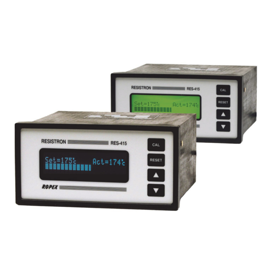
Controller functions 10.2.2 Display in home position tion, in other words it indicates the SET temperature as a digital value and the ACTUAL temperature as a digital If no settings are entered on the controller and no error value and a dynamic bar. message are present, the display is in the home posi- Specified heatsealing Measured ACTUAL... -
Page 24: Automatic Zero Calibration
Controller functions 10.5 Automatic zero calibration and the heatsealing band is heated up to the SET tem- perature. It remains at this temperature until the signal (AUTOCAL) is deactivated again. The "START" signal can be activated in two ways: Owing to the automatic zero calibration (AUTOCAL) function, there is no need to adjust the zero point manu- •... -
Page 25: Measuring Impulse Duration (As Of Software Revision 100)
Celsius to Fahrenheit. The length of the measuring impulses generated by the This parameter can only be set in the ROPEX controller can be set with this parameter. It may be visualization software ( section 10.10 "Dia-... -
Page 26: Diagnostic Interface/Visualization Software (As Of Software Revision 100)
"RESET" key or by switching the con- damage to the controller. troller off and then on again.Invalid error messages The ROPEX visualization software is described in a separate document. 10.11 Booster connection The RES-415 controller has a connection for an external switching amplifier (booster) as standard. - Page 27 100)" on page 26) to facilitate troubles- to be cleared quickly and efficiently hooting. The error codes described below can also be displayed in the ROPEX visualization software ( section 10.10 "Diagnostic interface/visualization software (as of soft- RES-415 Page 27...
- Page 28 Controller functions Page 28 RES-415...
- Page 29 Controller functions RES-415 Page 29...
- Page 30 Controller functions Page 30 RES-415...
-
Page 31: 10.14 Fault Areas And Causes
Controller functions 10.14 Fault areas and causes Temperature controller HARDWARE The table below explains the possible fault causes. Fault area Explanation Possible causes Load circuit interrupted after U - Wire break, heatsealing band break - Contacting to heatsealing band defective pickoff point ... - Page 32 Controller functions Fault area Explanation Possible causes - Up to software revision 027: DIP switches 4+5 configured incorrectly (I range) signal incorrect - As of software revision 100: I outside permissible range from 30…500A Turns through PEX-W2/W3 cur- - Check number of turns (two or more turns required for rent transformer incorrect currents <...
-
Page 33: Factory Settings
Celsius (as of software revision 106) [X] As of software revision 100 With ROPEX visualization software only. Maintenance The controller requires no special maintenance. the impulse transformer – is recommended. Dust depo- Regular inspection and/or tightening of the terminals –... -
Page 34: How To Order
Line filter LF- . . 480 06: Continuous current 6A, 480VAC, Art. No. 885500 35: Continuous current 35A, 480VAC, Art. No. 885506 Impulse transformer See ROPEX Application Report for design and ordering information Communication interface CI-USB-1 Art. No. 885650 For more accessories: "Accessories" leaflet... -
Page 35: Index
Index Index Impulse transformer Installation Accessories Installation procedure Adapter for top hat rail mounting Installation regulations Alarm output Alarm relay Alloy Ambient temperature Line filter Application Line frequency Application Report Line voltage AUTOCAL Automatic zero calibration AUTOTUNE Maintenance Measurement cable Measuring impulse duration Booster Modifications... - Page 36 Index Visualization software Undervoltage detection Wiring Wiring diagram View of controller Page 36 RES-415...
Need help?
Do you have a question about the RESISTRON RES-415 and is the answer not in the manual?
Questions and answers