
Related Manuals for Agilent Technologies G1314B


Summary of Contents for Agilent Technologies G1314B
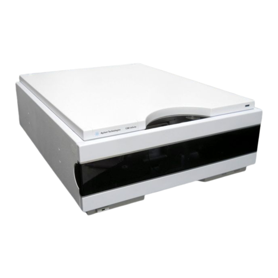
- Page 1 Agilent 1260 Infinity Variable Wavelength Detector User Manual Agilent Technologies...
- Page 2 Notices Warranty © Agilent Technologies, Inc. 2011-2012, receive no greater than Restricted Rights as 2013 defined in FAR 52.227-19(c)(1-2) (June The material contained in this docu- 1987). U.S. Government users will receive No part of this manual may be reproduced ment is provided “as is,”...
- Page 3 In This Guide In This Guide This manual covers the Agilent 1260 Infinity Variable Wavelength Detectors • G1314B Agilent 1260 Infinity Variable Wavelength Detector VL • G1314C Agilent 1260 Infinity Variable Wavelength Detector VL+ 1 Introduction to the Variable Wavelength Detector This chapter gives an introduction to the detector, instrument overview and internal connectors.
- Page 4 In This Guide 7 Error Information This chapter describes the meaning of detector error messages, and provides information on probable causes and suggested actions how to recover from error conditions. 8 Test Functions This chapter describes the detector’s built in test functions. 9 Maintenance This chapter provides general information on maintenance and repair of the detector.
-
Page 5: Table Of Contents
Contents Contents 1 Introduction to the Variable Wavelength Detector Introduction to the Detector Optical System Overview System Overview 2 Site Requirements and Specifications Site Requirements Physical Specifications Performance Specifications 3 Installing the Detector Unpacking the Detector Optimizing the Stack Configuration Installation Information on Leak and Waste Handling Installing the Detector Flow Connections to the Detector... - Page 6 Contents 7 Error Information What Are Error Messages General Error Messages Detector Error Messages 8 Test Functions Intensity Test Cell Test Wavelength Verification-Calibration ASTM Drift and Noise Test Quick Noise Test Dark Current Test Holmium Oxide Test 9 Maintenance Introduction to Maintenance Warnings and Cautions Overview of Maintenance Cleaning the Module...
- Page 7 Contents 10 Parts and Materials for Maintenance Overview of Maintenance Parts Standard Flow Cell 10 mm / 14 µL Micro Flow Cell, 5 mm / 1 µL (only for support) Micro Flow Cell 3 mm / 2 µL Semi-micro Flow Cell 6 mm / 5 µL High Pressure Flow Cell 10 mm / 14 µL Cuvette Holder Leak Parts...
- Page 8 Contents 13 Appendix General Safety Information Batteries Information Radio Interference Sound Emission UV Radiation Solvent Information Declaration of Conformity for HOX2 Filter Agilent Technologies on Internet Agilent 1260 Infinity VWD User Manual...
-
Page 9: Introduction To The Variable Wavelength Detector
Agilent 1260 Infinity VWD User Manual Introduction to the Variable Wavelength Detector Introduction to the Detector Optical System Overview Flow Cell G1314B/C Lamp Source Lens Assembly Entrance Slit Assembly Filter Assembly Mirror Assemblies M1 and M2 Grating Assembly Beam Splitter Assembly... -
Page 10: Introduction To The Detector
• data rate up to , see “Peakwidth Settings” on page 71, • 13 Hz for standard HPLC with G1314B VWD VL, • 55 Hz for fast- HPLC G1314C VWD VL+, • deuterium lamp for highest intensity and lowest detection limit over a wavelength range of 190 to 600 nm, •... -
Page 11: Optical System Overview
Introduction to the Variable Wavelength Detector Optical System Overview Optical System Overview The optical system of the detector is shown in the figure below. Its radiation source is a deuterium- arc discharge lamp for the ultraviolet (UV) wavelength range from 190 to 600 nm. The light beam from the deuterium lamp passes through a lens, a filter assembly, an entrance slit, a spherical mirror (M1), a grating, a second spherical mirror (M2), a beam splitter, and finally through a flow cell to the sample diode. - Page 12 Introduction to the Variable Wavelength Detector Optical System Overview Flow Cell A variety of flow- cell cartridges can be inserted using the same quick and simple mounting system. Figure 2 Cartridge Type Flow Cell Table 1 Flow Cell Data Semi-micro Micro High Pressure Maximum pressure...
- Page 13 Introduction to the Variable Wavelength Detector Optical System Overview G1314B/C Lamp The light source for the UV wavelength range is a deuterium lamp. As a result of plasma discharge in a low pressure deuterium gas, the lamp emits light over the 190 to 600 nm wavelength range.
- Page 14 Introduction to the Variable Wavelength Detector Optical System Overview Figure 3 Filter Assembly Mirror Assemblies M1 and M2 The instrument contains two spherical mirrors (M1 and M2). The beam adjustable is vertically and horizontally. Both mirrors are identical. Grating Assembly The grating separates the light beam into all its component wavelengths and reflects the light onto mirror #2.
- Page 15 Introduction to the Variable Wavelength Detector Optical System Overview Photo Diodes Assemblies Two photo diode assemblies are installed in the optical unit. The sample diode assembly is located on the left side of the optical unit. The reference diode assembly is located in the front of the optical unit. Photo Diode ADC (analog-to-digital converter) The photo diode current is directly converted to digital data direct photo current digitalization.
-
Page 16: System Overview
Introduction to the Variable Wavelength Detector System Overview System Overview Leak and Waste Handling The 1200 Infinity Series has been designed for safe leak and waste handling. It is important that all security concepts are understood and instructions are carefully followed. Agilent 1260 Infinity VWD User Manual... - Page 17 Introduction to the Variable Wavelength Detector System Overview Figure 4 Leak and waste handling concept (overview - typical stack configuration as an example) Agilent 1260 Infinity VWD User Manual...
- Page 18 Introduction to the Variable Wavelength Detector System Overview The solvent cabinet (1) is designed to store a maximum volume of 6 L solvent. The maximum volume for an individual bottle stored in the solvent cabinet should not exceed 2.5 L. For details, see the usage guideline for the Agilent 1200 Infinity Series Solvent Cabinets (a printed copy of the guideline has been shipped with the solvent cabinet, electronic copies are available on the Internet).
-
Page 19: Site Requirements And Specifications
Agilent 1260 Infinity VWD User Manual Site Requirements and Specifications Site Requirements Physical Specifications Performance Specifications Specification Conditions This chapter gives information on environmental requirements, physical and performance specifications. Agilent Technologies... -
Page 20: Site Requirements
Site Requirements and Specifications Site Requirements Site Requirements Site Requirements A suitable environment is important to ensure optimal performance of the instrument. Power Consideration The detector power supply has wide ranging capabilities, see “Physical Specifications” on page 24. It accepts any line voltage in the above mentioned range. - Page 21 Never operate your instrumentation from a power outlet that has no ground connection. ➔ Never use a power cord other than the Agilent Technologies power cord designed for your region. Use of unsupplied cables WA R N I N G Using cables not supplied by Agilent Technologies can lead to damage of the electronic components or personal injury.
- Page 22 Using power cords for unintended purposes can lead to personal injury or damage of electronic equipment. ➔ Never use the power cords that Agilent Technologies supplies with this instrument for any other equipment. Bench Space The detector dimensions and weight (see “Physical Specifications”...
- Page 23 “Physical Specifications” on page 24. ASTM drift tests require a temperature change below 2 °C/h (3.6 °F/h) over one hour period. Our published drift specification (refer also to “Performance Specifications G1314B” on page 25 or “Performance Specifications G1314C” on page 27) is based on these conditions. Larger ambient temperature changes will result in larger drift.
-
Page 24: Physical Specifications
Site Requirements and Specifications Physical Specifications Physical Specifications Table 2 Physical Specifications Type Specification Comments Weight 11 kg (25 lbs) Dimensions 140 x 345 x 435 mm (height × width × depth) (5.5 x 13.5 x 17 inches) Line voltage 100 –... -
Page 25: Performance Specifications
Site Requirements and Specifications Performance Specifications Performance Specifications Performance Specifications G1314B Table 3 Performance Specifications G1314B Type Specification Comments Detection type Double-beam photometer Light source Deuterium lamp Wavelength range 190 – 600 nm Short term noise (ASTM) “Specification <± 0.5·10 AU at 254 nm Conditions”... - Page 26 Site Requirements and Specifications Performance Specifications Table 3 Performance Specifications G1314B Type Specification Comments Control and data evaluation Agilent ChemStation for LC Analog outputs Recorder/integrator: 100 mV or 1 V, output range 0.001 to 2 AU, one output Communications Controller-area network...
- Page 27 Site Requirements and Specifications Performance Specifications Performance Specifications G1314C Table 4 Performance Specifications G1314C Type Specification Comments Detection type Double-beam photometer Light source Deuterium lamp Wavelength range 190 – 600 nm Short term noise (ASTM) “Specification <± 0.5·10 AU at 254 nm Conditions”...
- Page 28 Site Requirements and Specifications Performance Specifications Table 4 Performance Specifications G1314C Type Specification Comments Analog outputs Recorder/integrator: 100 mV or 1 V, output range 0.001 to 2 AU, one output Communications Controller-area network (CAN), RS-232C, APG Remote: ready, start, stop and shut-down signals, LAN (optional) Safety and maintenance...
- Page 29 Site Requirements and Specifications Performance Specifications Specification Conditions ASTM: “Standard Practice for Variable Wavelength Photometric Detectors Used in Liquid Chromatography”. Reference conditions: Standard flow cell, path length 10 nm, flow 1 mL/min LC- grade methanol. Noise: <± 0.5·10 AU at 254 nm, TC 2 s, ASTM RT = 2.2 * TC Linearity: Linearity is measured with caffeine at 265 nm.
- Page 30 Site Requirements and Specifications Performance Specifications Agilent 1260 Infinity VWD User Manual...
-
Page 31: Installing The Detector
Optimizing the Stack Configuration One Stack Configuration Two Stack Configuration Installation Information on Leak and Waste Handling Installing the Detector Flow Connections to the Detector This chapter provides information on unpacking, checking on completeness, stack considerations and installation of the module. Agilent Technologies... -
Page 32: Unpacking The Detector
Unpacking the Detector Damaged Packaging If the delivery packaging shows signs of external damage, please call your Agilent Technologies sales and service office immediately. Inform your service representative that the instrument may have been damaged during shipment. "Defective on arrival" problems C A U T I O N If there are signs of damage, please do not attempt to install the module. -
Page 33: Delivery Checklist
1 per order shipment - not module specific) Accessory kit (see “Accessory Kit” on page 150) Detector Accessory Kit Contents The G1314B/C VWD is shipped with Accessory kit (G1314- 68755) (see “Accessory Kit” on page 150). Agilent 1260 Infinity VWD User Manual... -
Page 34: Optimizing The Stack Configuration
Installing the Detector Optimizing the Stack Configuration Optimizing the Stack Configuration If your module is part of a complete Agilent Liquid Chromatograph, you can ensure optimum performance by installing the following configurations. These configurations optimize the system flow path, ensuring minimum delay volume. One Stack Configuration Ensure optimum performance by installing the modules of the Agilent 1260 Infinity LC System in the following configuration (See... - Page 35 Installing the Detector Optimizing the Stack Configuration Figure 5 Recommended Stack Configuration for 1260 Infinity (Front View) Agilent 1260 Infinity VWD User Manual...
- Page 36 Installing the Detector Optimizing the Stack Configuration Figure 6 Recommended Stack Configuration for 1260 Infinity (Rear View) Agilent 1260 Infinity VWD User Manual...
-
Page 37: Two Stack Configuration
Installing the Detector Optimizing the Stack Configuration Two Stack Configuration To avoid excessive height of the stack when the autosampler thermostat is added to the system it is recommended to form two stacks. Some users prefer the lower height of this arrangement even without the autosampler thermostat. - Page 38 Installing the Detector Optimizing the Stack Configuration Figure 8 Recommended Two Stack Configuration for 1260 Infinity (Rear View) Agilent 1260 Infinity VWD User Manual...
-
Page 39: Installation Information On Leak And Waste Handling
Installing the Detector Installation Information on Leak and Waste Handling Installation Information on Leak and Waste Handling The Agilent 1200 Infinity Series has been designed for safe leak and waste handling. It is important that all security concepts are understood and instructions are carefully followed. - Page 40 Installing the Detector Installation Information on Leak and Waste Handling Figure 9 Leak and waste handling (overview - typical stack configuration as an example) Agilent 1260 Infinity VWD User Manual...
- Page 41 Installing the Detector Installation Information on Leak and Waste Handling Solvent cabinet Leak pan Leak pan's outlet port (A), leak funnel (B) and corrugated waste tube (C) Waste tube of the sampler’s needle wash Condense drain outlet of the autosampler cooler Waste tube of the purge valve Waste tube 1 Stack the modules according to the adequate stack configuration.
- Page 42 Installing the Detector Installation Information on Leak and Waste Handling Figure 10 Warning label (illustration for correct waste tubing) Agilent 1260 Infinity VWD User Manual...
-
Page 43: Installing The Detector
Installing the Detector Installing the Detector Installing the Detector Parts required Description Detector Power cord LAN cable (cross-over or twisted pair network cable) Agilent ChemStation or other control software G4208A Instant Pilot For other cables see below and section “Cable Overview” on page 152. - Page 44 Installing the Detector Installing the Detector 3 Ensure the line power switch at the front of the detector is OFF. Figure 11 Front View of Detector The figure above shows the flow cell already installed. The flow cell area is closed with a N O T E cover.
- Page 45 Installing the Detector Installing the Detector 9 Turn ON power by pushing the button at the lower left- hand side of the detector. The status LED should be green. Figure 12 Rear View of Detector The detector is turned ON when the line power switch is pressed and the green indicator N O T E lamp is illuminated.
-
Page 46: Flow Connections To The Detector
Installing the Detector Flow Connections to the Detector Flow Connections to the Detector Tools required Description Wrench, 1/4 – 5/16 inch (for capillary connections) Parts required Description G1314-68755 Accessory kit Hardware required Other modules depend on system setup Preparations Detector is installed in the LC system. Toxic, flammable and hazardous solvents, samples and reagents WA R N I N G The handling of solvents, samples and reagents can hold health and safety risks. - Page 47 Installing the Detector Flow Connections to the Detector Press the release buttons and remove the front cover to Remove the plastic dummy cover. have access to the lamp area. If the detector uses a metal plate, loose the screws of the flow cell dummy plate by turning each screw one turn.
- Page 48 Installing the Detector Flow Connections to the Detector Connect the newly assembled fitting of the capillary to Connect the PEEK waste capillary to the outlet the inlet connector and connect the other end of the connector. capillary to the column. Establish a flow and observe for leakage.
-
Page 49: Using The Detector
Running the Sample and Verifying the Results Special Settings of the Detector Control Settings Online Spectra Scanning with the VWD Analog Output Settings Special Setpoints This chapter provides information on how to set up the detector for an analysis and explains the basic settings. Agilent Technologies... -
Page 50: Leak And Waste Handling
Using the Detector Leak and Waste Handling Leak and Waste Handling Toxic, flammable and hazardous solvents, samples and reagents WA R N I N G The handling of solvents, samples and reagents can hold health and safety risks. ➔ When working with these substances observe appropriate safety procedures (for example by wearing goggles, safety gloves and protective clothing) as described in the material handling and safety data sheet supplied by the vendor, and follow good laboratory practice. -
Page 51: Setting Up An Analysis
Using the Detector Setting up an Analysis Setting up an Analysis This chapter can be used for • preparing the system, • to learn the set up of an HPLC analysis and • to use it as an instrument check to demonstrate that all modules of the system are correctly installed and connected. - Page 52 Using the Detector Setting up an Analysis Table 6 Choice of Priming Solvents for Different Purposes Activity Solvent Comments After an installation Isopropanol Best solvent to flush air out of the system When switching between reverse Isopropanol Best solvent to flush air out of the phase and normal phase (both times) system After an installation...
-
Page 53: Requirements And Conditions
Using the Detector Setting up an Analysis Requirements and Conditions What You Will Need The table below lists the items you need to have for the set up of the analysis. Some of these are optional (not required for the basic system). Table 7 What you will need Agilent 1200... - Page 54 Using the Detector Setting up an Analysis Conditions A single injection of the isocratic test standard is made under the conditions given in Table 8 on page 54: Table 8 Conditions Flow 1.5 mL/min Stoptime 8 min Solvent 100% (30% water/70% Acetonitrile) Temperature Ambient Wavelength...
-
Page 55: Optimization Of The System
Using the Detector Setting up an Analysis Typical Chromatogram A typical chromatogram for this analysis is shown in Figure 13 page 55. The exact profile of the chromatogram will depend on the chromatographic conditions. Variations in solvent quality, column packing, standard concentration and column temperature will all have a potential effect on peak retention and response. -
Page 56: Preparing The Hplc System
Using the Detector Setting up an Analysis Preparing the HPLC System 1 Turn on the Agilent ChemStation PC and the monitor. 2 Turn on the modules. 3 Start the Agilent ChemStation software. If the pump, autosampler, thermostatted column compartment and detector are found, the Agilent ChemStation screen should look like shown in Figure 14 on page 56. - Page 57 Using the Detector Setting up an Analysis 4 Turn on the detector lamp, pump and autosampler by clicking the System On button or the buttons below the module icons on the graphical user interface (GUI). After some time, the pump, thermostatted column compartment and detector module will turn to green.
- Page 58 Using the Detector Setting up an Analysis 5 Purge the pump. For more information “Priming and Purging the System” on page 51. 6 Allow the detector to warm up of at least 60 minutes to provide a stable baseline (see example in Figure 16 on page 58).
- Page 59 Using the Detector Setting up an Analysis 8 Click on the Load Method button, select DEF_LC.M and press OK. Alternatively, double- click on the method in the method window. The default LC method parameters are transferred into the modules. Figure 17 Loading Default LC Method Agilent 1260 Infinity VWD User Manual...
- Page 60 Using the Detector Setting up an Analysis 9 Click on the module icons (Figure 18 on page 60) and open the Setup of these modules. Figure 19 on page 61 shows the detector settings (do not change the detector parameters at this time). Figure 18 Open the module menu 10 Enter the pump parameters mentioned under...
- Page 61 Using the Detector Setting up an Analysis • 1 signal with individual wavelength setting • stop and post time can be set (if required) • peakwidth depends on the peaks in the chromatogram, see “Peakwidth Settings” page 71. • time table for programmable actions during the run •...
- Page 62 Using the Detector Setting up an Analysis 11 Pump the water/acetonitrile (30/70 %) mobile phase through the column for 10 minutes for equilibration. 12 Click the button and select Change... to open the Signal Plot information. Select the Pump: Pressure and the VWD A: Signal 254 as signals.
- Page 63 Using the Detector Setting up an Analysis The Online Plot (Figure 21 on page 63) shows both, the pump pressure and the detector absorbance signals. Pressing Adjust the signals can be reset to the offset value and Balance would do a balance on the detector.
- Page 64 Using the Detector Setting up an Analysis 14 Select the menu item RunControl > Sample Info and enter information on page 64). Press OK to leave this about this application (Figure 22 screen. Figure 22 Sample Information 15 Fill the content of an isocratic standard sample ampoule into a vial and seal the vial with a cap and place the vial into autosampler tray (position #1).
-
Page 65: Running The Sample And Verifying The Results
Using the Detector Setting up an Analysis Running the Sample and Verifying the Results 1 To start a run select the menu item RunControl > Run Method. 2 This will start the modules and the online plot on the Agilent ChemStation will show the resulting chromatogram. -
Page 66: Special Settings Of The Detector
Using the Detector Special Settings of the Detector Special Settings of the Detector In this chapter special settings of the detector are described. Control Settings • Lamp: turn on and off of UV-lamp. • At Power On: automatic lamp-on at power on. -
Page 67: Online Spectra
Using the Detector Special Settings of the Detector Online Spectra 1 To view the online spectra select Online Spectra. This online spectrum is taken during a stop-flow condition only while the peak is kept in the N O T E flow cell, see “Scanning with the VWD”... -
Page 68: Scanning With The Vwd
Using the Detector Special Settings of the Detector Scanning with the VWD 1 Set up a run. 2 Start a run. 3 While running on the baseline, select from the menu Instrument > More VWD > Blank Scan. A background scan is stored in the memory. •... -
Page 69: Analog Output Settings
Using the Detector Special Settings of the Detector Analog Output Settings 1 To change the Output Range of the analog outputs select VWD Control. 2 To change the offset and the attenuation select VWD Signal > More. • Analog Output Range: can be set to either 100 mV or 1 V full scale. -
Page 70: Special Setpoints
Using the Detector Special Settings of the Detector Special Setpoints 1 To change the offset and the attenuation select VWD Signal > More > Special Setpoints. • Margin for negative Absorbance: Use this field to modify the detector’s signal handling to increase the margin for negative absorbance. - Page 71 Using the Detector Special Settings of the Detector Peakwidth Settings Do not use peak width shorter than necessary, see also “Set the Detector Parameters” N O T E page 78. 1 To change the Peakwidth settings select Setup Detector Signals. 2 In the section Peakwidth (Responsetime) click on the drop- down list.
- Page 72 Using the Detector Special Settings of the Detector Table 9 Peak Width — Response Time — Data Rate (G1314B VWD) Response Time (s) Data Rate (Hz) Peak Width (min) <0.005 0.12 13.74 >0.005 0.12 13.74 >0.01 0.25 13.74 >0.025 13.74 >0.05...
-
Page 73: How To Optimize The Detector
Agilent 1260 Infinity VWD User Manual How to optimize the detector Optimizing the Detector Performance Match the Flow Cell to the Column Set the Detector Parameters This chapter gives hints on how to select the detector parameters and the flow cell. Agilent Technologies... -
Page 74: Optimizing The Detector Performance
How to optimize the detector Optimizing the Detector Performance Optimizing the Detector Performance The detector has a variety of parameters that can be used to optimize performance. The information below will guide you on how to get the best detector performance. -
Page 75: Match The Flow Cell To The Column
How to optimize the detector Match the Flow Cell to the Column Match the Flow Cell to the Column Figure 30 on page 75 recommends the flow cell that matches the column used. If more than one selection is appropriate, use the larger flow cell to get the best detection limit. - Page 76 How to optimize the detector Match the Flow Cell to the Column Flow Cell Path Length Lambert- Beer’s law shows a linear relationship between the flow cell path length and absorbance. where is the transmission, defined as the quotient of the intensity of the transmitted light I divided by the intensity of the incident light, I is the extinction coefficient, which is a characteristic of a given substance under a precisely-defined set of conditions of wavelength, solvent, temperature and other...
- Page 77 How to optimize the detector Match the Flow Cell to the Column Figure 31 Influence of Cell Path Length on Signal Height Traditionally LC analysis with UV detectors is based on comparing measurements with internal or external standards. To check photometric accuracy of the Agilent 1200 Series Infinity Variable Wavelength Detector it is necessary to have more precise information on path lengths of the VWD flow cells.
-
Page 78: Set The Detector Parameters
How to optimize the detector Set the Detector Parameters Set the Detector Parameters 1 Set peakwidth as close as possible to the width (at half height) of a narrow peak of interest. Refer to “Peakwidth Settings” on page 71. 2 Choose the sample wavelength •... -
Page 79: Troubleshooting And Diagnostics
Agilent 1260 Infinity VWD User Manual Troubleshooting and Diagnostics Overview of the Detector’s Indicators and Test Functions Status Indicators Power Supply Indicator Module Status Indicator Available Tests versus Interfaces Agilent Lab Advisor Software Overview about the troubleshooting and diagnostic features. Agilent Technologies... -
Page 80: Overview Of The Detector's Indicators And Test Functions
Troubleshooting and Diagnostics Overview of the Detector’s Indicators and Test Functions Overview of the Detector’s Indicators and Test Functions Status Indicators The detector is provided with two status indicators which indicate the operational state (prerun, run, and error states) of the detector. The status indicators provide a quick visual check of the operation of the detector. -
Page 81: Status Indicators
Troubleshooting and Diagnostics Status Indicators Status Indicators Two status indicators are located on the front of the detector. The lower left indicates the power supply status, the upper right indicates the detector status. Figure 32 Location of Status Indicators Power Supply Indicator The power supply indicator is integrated into the main power switch. -
Page 82: Module Status Indicator
Troubleshooting and Diagnostics Status Indicators Module Status Indicator The module status indicator indicates one of six possible module conditions: • When the status indicator is OFF (and power switch light is on), the module is in a prerun condition, and is ready to begin an analysis. •... -
Page 83: Available Tests Versus Interfaces
Troubleshooting and Diagnostics Available Tests versus Interfaces Available Tests versus Interfaces Depending on the used interface, the available tests and the screens/reports may vary. N O T E Preferred tool should be the Agilent Diagnostic Software, see “Agilent Lab Advisor Software”... -
Page 84: Agilent Lab Advisor Software
Troubleshooting and Diagnostics Agilent Lab Advisor Software Agilent Lab Advisor Software The Agilent Lab Advisor software is a standalone product that can be used with or without data system. Agilent Lab Advisor software helps to manage the lab for high quality chromatographic results and can monitor in real time a single Agilent LC or all the Agilent GCs and LCs configured on the lab intranet. -
Page 85: Error Information
Cutoff filter doesn't decrease the light intensity at 250 nm ADC Hardware Error Cover Violation This chapter describes the meaning of detector error messages, and provides information on probable causes and suggested actions how to recover from error conditions. Agilent Technologies... -
Page 86: What Are Error Messages
Error Information What Are Error Messages What Are Error Messages Error messages are displayed in the user interface when an electronic, mechanical, or hydraulic (flow path) failure occurs which requires attention before the analysis can be continued (for example, repair, or exchange of consumables is necessary). -
Page 87: General Error Messages
Error Information General Error Messages General Error Messages General error messages are generic to all Agilent 1200 Infinity Series modules. Timeout Error ID: 0062 The timeout threshold was exceeded. Probable cause Suggested actions Check the logbook for the occurrence and The analysis was completed successfully, source of a not-ready condition. -
Page 88: Shutdown
Error Information General Error Messages Shutdown Error ID: 0063 An external instrument has generated a shutdown signal on the remote line. The module continually monitors the remote input connectors for status signals. A LOW signal input on pin 4 of the remote connector generates the error message. -
Page 89: Lost Can Partner
Error Information General Error Messages Probable cause Suggested actions Ensure the instrument showing the not-ready Not-ready condition in one of the condition is installed correctly, and is set up instruments connected to the remote line. correctly for analysis. Exchange the remote cable. Defective remote cable. -
Page 90: Leak
Error Information General Error Messages Leak Error ID: 0064 A leak was detected in the module. The signals from the two temperature sensors (leak sensor and board- mounted temperature- compensation sensor) are used by the leak algorithm to determine whether a leak is present. When a leak occurs, the leak sensor is cooled by the solvent. -
Page 91: Leak Sensor Short
Error Information General Error Messages Leak Sensor Short Error ID: 0082 The leak sensor in the module has failed (short circuit). The current through the leak sensor is dependent on temperature. A leak is detected when solvent cools the leak sensor, causing the leak sensor current to change within defined limits. -
Page 92: Compensation Sensor Short
Error Information General Error Messages Compensation Sensor Short Error ID: 0080 The ambient- compensation sensor (NTC) on the main board in the module has failed (open circuit). The resistance across the temperature compensation sensor (NTC) on the main board is dependent on ambient temperature. The change in resistance is used by the leak circuit to compensate for ambient temperature changes. -
Page 93: Open Cover
Error Information General Error Messages Probable cause Suggested actions Please contact your Agilent service Fan cable disconnected. representative. Please contact your Agilent service Defective fan. representative. Please contact your Agilent service Defective main board. representative. Open Cover Error ID: 0205 The top foam has been removed. -
Page 94: Detector Error Messages
Error Information Detector Error Messages Detector Error Messages These errors are detector specific. UV lamp: no current Error ID: 7450 The lamp anode current is missing. The processor continually monitors the anode current drawn by the lamp during operation. If the anode current falls below the lower current limit, the error message is generated. -
Page 95: Ignition Failed
Error Information Detector Error Messages Probable cause Suggested actions Exchange the lamp. Defective or non-Agilent lamp. Please contact your Agilent service Defective power supply. representative. Please contact your Agilent service Defective main board. representative. Ignition Failed Error ID: 7452 The lamp failed to ignite. The processor monitors the lamp current during the ignition cycle. -
Page 96: No Heater Current
Error Information Detector Error Messages No heater current Error ID: 7453 The lamp heater current in the detector is missing. During lamp ignition, the processor monitors the heater current. If the current does not rise above the lower limit within 1 , the error message is generated. Probable cause Suggested actions Ensure the lamp is connected. -
Page 97: Wavelength Calibration Setting Failed
Error Information Detector Error Messages Wavelength calibration setting failed Error ID: 7310 The intensity maximum was not found during wavelength calibration. Calibration 0 Failed: Zero-order calibration failed. Calibration 1 Failed: 656 nm calibration failed. Probable cause Suggested actions Switch on the lamp. Lamp is OFF. -
Page 98: Wavelength Holmium Check Failed
Error Information Detector Error Messages Wavelength holmium check failed Error ID: 7318 The holmium oxide test in the detector has failed. During the holmium test, the detector moves the holmium filter into the light path, and compares the measured absorbance maxima of the holmium oxide filter with expected maxima. -
Page 99: Wavelength Test Failed
Error Information Detector Error Messages Probable cause Suggested actions Please contact your Agilent service Motor is not connected. representative. Please contact your Agilent service Defective motor. representative. Please contact your Agilent service Defective/missing grating or filter. representative. Please contact your Agilent service Cable/connector defective. -
Page 100: Cutoff Filter Doesn't Decrease The Light Intensity At 250 Nm
Error Information Detector Error Messages Cutoff filter doesn't decrease the light intensity at 250 nm Error ID: 7813 The automatic filter check after lamp ignition has failed. When the lamp is switched on, the detector moves the cutoff filter into the light path. If the filter is functioning correctly, a decrease in lamp intensity is seen. -
Page 101: Cover Violation
Error Information Detector Error Messages Cover Violation Error ID: 7461 The top foam has been removed. The sensor on the main board detects when the top foam is in place. If the foam is removed while the lamps are on (or if an attempt is made to switch on for example the lamps with the foam removed), the lamps are switched off, and the error message is generated. - Page 102 Error Information Detector Error Messages Agilent 1260 Infinity VWD User Manual...
-
Page 103: Test Functions
Intensity Test Failed Cell Test Wavelength Verification-Calibration ASTM Drift and Noise Test Quick Noise Test Dark Current Test Dark Current Test Failed Holmium Oxide Test Holmium Oxide Test Failed This chapter describes the detector’s built in test functions. Agilent Technologies... -
Page 104: Intensity Test
Test Functions Intensity Test Intensity Test The intensity test measures the intensity of the deuterium lamp over the full VWD wavelength range (190 – 600 nm). The test can be used to determine the performance of the lamp, and to check for dirty or contaminated flow cell windows. -
Page 105: Intensity Test Failed
Test Functions Intensity Test Instensity Test with Agilent Lab Advisor Figure 33 Intensity Test with Agilent Lab Advisor Intensity Test Failed Probable cause Suggested actions Ensure the flow cell is filled with water. Empty flow cell Repeat the test with the flow cell removed. If Flow cell windows dirty the test passes, exchange the flow cell windows. -
Page 106: Cell Test
Test Functions Cell Test Cell Test The cell test compares the intensity of the deuterium lamp measured by the sample and reference diodes (unfiltered and not logarithmized) when the grating is in the zero- order position. The resulting intensity ratio (sample:reference) is a measure of the amount of light absorbed by the flow cell. - Page 107 Test Functions Cell Test Figure 34 Cell Test with Lab Advisor Checking the Photocurrent with the Instant Pilot Figure 35 Checking the Photocurrent with the Instant Pilot Agilent 1260 Infinity VWD User Manual...
-
Page 108: Wavelength Verification-Calibration
Test Functions Wavelength Verification-Calibration Wavelength Verification-Calibration Wavelength calibration of the detector is done using the zero- order position and 656 nm emission line position of the deuterium lamp. The calibration procedure involves two steps. First the grating is calibrated on the zero- order position. - Page 109 Test Functions Wavelength Verification-Calibration Wavelength Verification/Calibration with Agilent Lab Advisor Figure 36 Wavelength Verification and Calibration (Agilent Lab Advisor) Agilent 1260 Infinity VWD User Manual...
-
Page 110: Astm Drift And Noise Test
Test Functions ASTM Drift and Noise Test ASTM Drift and Noise Test The ASTM Drift and Noise test determines the detector noise over a period of 20 min. The test is done with HPLC- grade water flowing through the flow cell at 1 mL/min. On completion of the test, the noise result is displayed automatically. -
Page 111: Quick Noise Test
Test Functions Quick Noise Test Quick Noise Test The noise test measures the noise of the detector, with HPLC- grade water flowing through the flow cell at 1 mL/min, in one minute intervals over a total of 5 min. The noise of the detector is calculated by using the maximum amplitude for all random variations of the detector signal of frequencies greater than one cycle per hour. -
Page 112: Dark Current Test
Test Functions Dark Current Test Dark Current Test The dark- current test measures the leakage current from the sample and reference circuits. The test is used to check for defective sample or reference diodes or ADC circuits which may cause non- linearity or excessive baseline noise. -
Page 113: Dark Current Test Failed
Test Functions Dark Current Test Dark Current Test Failed Probable cause Suggested actions Please contact your Agilent service Defective sample or reference diode. representative. Please contact your Agilent service Defective sample or reference ADC board. representative. Please contact your Agilent service Defective main board. -
Page 114: Holmium Oxide Test
Test Functions Holmium Oxide Test Holmium Oxide Test This test verifies the calibration of the detector against the three wavelength maxima of the built- in holmium oxide filter. The test displays the difference between the expected and measured maxima. The figure below shows a holmium test spectrum. - Page 115 Test Functions Holmium Oxide Test Running the test with Agilent Lab Advisor Figure 40 Holmium Test with Agilent Lab Advisor Agilent 1260 Infinity VWD User Manual...
-
Page 116: Holmium Oxide Test Failed
Test Functions Holmium Oxide Test Holmium Oxide Test Failed Probable cause Suggested actions Recalibrate the detector. Detector not calibrated. Repeat the test with the flow cell removed. If Dirty or defective flow cell. the test is OK, exchange the flow cell components. -
Page 117: Maintenance
Exchanging a Flow Cell Repairing the Flow Cells Using the Cuvette Holder Correcting Leaks Replacing Leak Handling System Parts Replacing the Interface Board Replacing the Module’s Firmware This chapter provides general information on maintenance and repair of the detector. Agilent Technologies... -
Page 118: Introduction To Maintenance
Maintenance Introduction to Maintenance Introduction to Maintenance The module is designed for easy maintenance. Maintenance can be done from the front with module in place in the system stack. There are no serviceable parts inside. N O T E Do not open the module. Agilent 1260 Infinity VWD User Manual... -
Page 119: Warnings And Cautions
Maintenance Warnings and Cautions Warnings and Cautions Toxic, flammable and hazardous solvents, samples and reagents WA R N I N G The handling of solvents, samples and reagents can hold health and safety risks. ➔ When working with these substances observe appropriate safety procedures (for example by wearing goggles, safety gloves and protective clothing) as described in the material handling and safety data sheet supplied by the vendor, and follow good laboratory practice. - Page 120 Maintenance Warnings and Cautions Personal injury or damage to the product WA R N I N G Agilent is not responsible for any damages caused, in whole or in part, by improper use of the products, unauthorized alterations, adjustments or modifications to the products, failure to comply with procedures in Agilent product user guides, or use of the products in violation of applicable laws, rules or regulations.
-
Page 121: Overview Of Maintenance
Maintenance Overview of Maintenance Overview of Maintenance The following pages describe maintenance (simple repairs) of the detector that can be carried out without opening the main cover. Table 13 Simple Repairs Procedures Typical Frequency Notes Deuterium lamp If noise and/or drift exceeds your application limits or A VWD test should be performed after exchange lamp does not ignite. -
Page 122: Cleaning The Module
Maintenance Cleaning the Module Cleaning the Module To keep the module case clean, use a soft cloth slightly dampened with water, or a solution of water and mild detergent. Liquid dripping into the electronic compartment of your module can cause shock WA R N I N G hazard and damage the module ➔... -
Page 123: Exchanging A Lamp
Maintenance Exchanging a Lamp Exchanging a Lamp When If noise or drift exceeds application limits or lamp does not ignite Tools required Description Screwdriver, Pozidriv #1 PT3 Parts required Description G1314-60100 Deuterium lamp Preparations Turn the lamp OFF. Injury by touching hot lamp WA R N I N G If the detector has been in use, the lamp may be hot. - Page 124 Maintenance Exchanging a Lamp Press the release buttons and remove the front cover to Unscrew the lamp cover and remove it. have access to the lamp area. Unscrew, disconnect and replace the lamp. Insert, fix and Replace the lamp cover. reconnect the lamp.
- Page 125 Maintenance Exchanging a Lamp Next Steps: Replace the front cover. Reset the lamp counter as described in the User Interface documentation. Turn the lamp ON. Give the lamp more than 10 min to warm-up. Perform “Wavelength Verification-Calibration” page 108 to check the correct positioning of the lamp. Agilent 1260 Infinity VWD User Manual...
-
Page 126: Exchanging A Flow Cell
Maintenance Exchanging a Flow Cell Exchanging a Flow Cell When If an application needs a different type of flow cell or the flow cell needs repair. Tools required Description Wrench, 1/4 inch for capillary connections Parts required Description G1314-60186 Standard flow cell 10 mm, 14 µL, 40 bar (with RFID tag) G1314-60187 Micro flow cell 3 mm, 2 µL, 120 bar... - Page 127 Maintenance Exchanging a Flow Cell Unscrew the thumb screws parallel and remove the flow Press the flow cell completely into the slot and tighten cell. the cell screws (both parallel) until the mechanical stop. Reconnect the inlet and outlet capillaries to the flow cell. N O T E If you want to maintain flow cell parts, see “Repairing...
-
Page 128: Repairing The Flow Cells
Maintenance Repairing the Flow Cells Repairing the Flow Cells When If the flow cell needs repair due to leaks or contaminations. Tools required Description Wrench, 1/4 inch for capillary connections Wrench, 4 mm hexagonal Toothpick Parts required Description “Standard Flow Cell 10 mm / 14 µL” on page 139 “Micro Flow Cell 3 mm / 2 µL”... - Page 129 Maintenance Repairing the Flow Cells Cleaning the Flow Cell Parts 1 Pour isopropanol into the cell hole and wipe clean with a piece of lint- free cloth. 2 Clean the windows with ethanol or methanol. Dry it with a piece of lint- free cloth.
-
Page 130: Using The Cuvette Holder
Maintenance Using the Cuvette Holder Using the Cuvette Holder This cuvette holder can be placed instead of a flow cell in the variable wavelength detector. Standard cuvettes with standards in it, for example, National Institute of Standards & Technology (NIST) holmium oxide solution standard, can be fixed in it. - Page 131 Maintenance Using the Cuvette Holder Locate the cuvette holder on the desk. Unscrew the bracket. Insert the cuvette with the sample into the holder. The Replace the bracket and fix the cuvette. clear side of the cuvette must be visible. Next Steps: Install the cuvette holder in the instrument.
-
Page 132: Correcting Leaks
Maintenance Correcting Leaks Correcting Leaks When If a leakage has occurred in the flow cell area or at the capillary connections. Tools required Description Tissue Wrench, 1/4 inch for capillary connections 1 Remove the front cover. 2 Use tissue to dry the leak sensor area. 3 Observe the capillary connections and the flow cell area for leaks and correct, if required. -
Page 133: Replacing Leak Handling System Parts
Maintenance Replacing Leak Handling System Parts Replacing Leak Handling System Parts When If the parts are corroded or broken. Tools required None Parts required Description 5041-8389 Leak funnel holder 5041-8388 Leak funnel 5062-2463 Corrugated tubing, PP, 6.5 mm id, 5 m 1 Remove the front cover to have access to the leak handling system. -
Page 134: Replacing The Interface Board
Maintenance Replacing the Interface Board Replacing the Interface Board When When defective or for installation of the board or for all repairs inside the detector. Parts required Description G1351-68701 Interface board (BCD) with external contacts and BCD outputs G1369B or Interface board (LAN) G1369-60002 G1369C or... -
Page 135: Replacing The Module's Firmware
Maintenance Replacing the Module’s Firmware Replacing the Module’s Firmware When The installation of newer firmware might be necessary • if a newer version solves problems of older versions or • to keep all systems on the same (validated) revision. The installation of older firmware might be necessary •... - Page 136 Maintenance Replacing the Module’s Firmware Module Specific Information Table 14 Module Specific Information (G1314B/C) G1314B VWD G1314C VWD SL Initial firmware A.06.02 A.06.02 Compatibility with 1100 / 1200 yes, all modules should have the firmware from the same set. series modules...
-
Page 137: Parts And Materials For Maintenance
Micro Flow Cell 3 mm / 2 µL Semi-micro Flow Cell 6 mm / 5 µL High Pressure Flow Cell 10 mm / 14 µL Cuvette Holder Leak Parts Kits This chapter provides information on parts for maintenance. Agilent Technologies... -
Page 138: Overview Of Maintenance Parts
Parts and Materials for Maintenance Overview of Maintenance Parts Overview of Maintenance Parts Description 5181-1516 CAN cable, Agilent module to module, 0.5 m 5181-1519 CAN cable, Agilent module to module, 1 m G1351-68701 Interface board (BCD) with external contacts and BCD outputs G1369C or Interface board (LAN) G1369-60012... -
Page 139: Standard Flow Cell 10 Mm / 14 Μl
Parts and Materials for Maintenance Standard Flow Cell 10 mm / 14 µL Standard Flow Cell 10 mm / 14 µL Item Description G1314-60186 Standard flow cell 10 mm, 14 µL, 40 bar (with RFID tag) 5062-8522 Capillary column - detector PEEK 600 mm lg, 0.17 mm i.d., 1/16 inch o.d. G1314-65061 Cell Repair Kit, includes 2x Gasket #1, 2x Gasket #2, 2x Window Quartz G1314-65062... -
Page 140: Micro Flow Cell, 5 Mm / 1 Μl (Only For Support)
Parts and Materials for Maintenance Micro Flow Cell, 5 mm / 1 µL (only for support) Micro Flow Cell, 5 mm / 1 µL (only for support) Item Description G1314-60081 Micro flow cell, 5 mm, 1 µL, 40 bar 5021-1823 Capillary column –... - Page 141 Parts and Materials for Maintenance Micro Flow Cell, 5 mm / 1 µL (only for support) Figure 45 Micro Flow Cell (5 mm, 1 µL, 40 bar) Agilent 1260 Infinity VWD User Manual...
-
Page 142: Micro Flow Cell 3 Mm / 2 Μl
Parts and Materials for Maintenance Micro Flow Cell 3 mm / 2 µL Micro Flow Cell 3 mm / 2 µL Item Description G1314-60187 Micro flow cell 3 mm, 2 µL, 120 bar (with RFID tag) 5021-1823 Capillary column – detector SST 400 mm lg, 0.12 mm i.d. 79883-22402 Window screw 5062-8553... - Page 143 Parts and Materials for Maintenance Micro Flow Cell 3 mm / 2 µL Figure 46 Micro Flow Cell Agilent 1260 Infinity VWD User Manual...
-
Page 144: Semi-Micro Flow Cell 6 Mm / 5 Μl
Parts and Materials for Maintenance Semi-micro Flow Cell 6 mm / 5 µL Semi-micro Flow Cell 6 mm / 5 µL The semi-micro #1 and #2 gaskets (items 6 and 7) look very similar. Do not mix them up. N O T E Item Description G1314-60183... - Page 145 Parts and Materials for Maintenance Semi-micro Flow Cell 6 mm / 5 µL Figure 47 Semi-micro Flow Cell Agilent 1260 Infinity VWD User Manual...
-
Page 146: High Pressure Flow Cell 10 Mm / 14 Μl
Parts and Materials for Maintenance High Pressure Flow Cell 10 mm / 14 µL High Pressure Flow Cell 10 mm / 14 µL Item Description G1314-60182 High pressure flow cell 10 mm, 14 µL, 400 bar (with RFID tag) G1315-87311 Capillary ST 0.17 mm x 380 mm S/S G1314-20047 Cell screw... - Page 147 Parts and Materials for Maintenance High Pressure Flow Cell 10 mm / 14 µL Figure 48 High Pressure Flow Cell Agilent 1260 Infinity VWD User Manual...
-
Page 148: Cuvette Holder
Parts and Materials for Maintenance Cuvette Holder Cuvette Holder For information the use of the cuvette holder, refer to “Using the Cuvette Holder” on page 130. Description G1314-60200 Cuvette Holder Figure 49 Cuvette Holder Agilent 1260 Infinity VWD User Manual... -
Page 149: Leak Parts
Parts and Materials for Maintenance Leak Parts Leak Parts Item Description 5041-8388 Leak funnel 5041-8389 Leak funnel holder 5041-8387 Tube clip 5062-2463 Corrugated tubing, PP, 6.5 mm id, 5 m 5062-2463 Corrugated tubing, PP, 6.5 mm id, 5 m Figure 50 Leak Parts Agilent 1260 Infinity VWD User Manual... -
Page 150: Kits
Parts and Materials for Maintenance Kits Kits HPLC System Tool Kit HPLC System Tool Kit (G4203- 68708) contains some accessories and tools needed for installation and maintenance of the module. Accessory Kit Accessory kit (G1314- 68755) contains some accessories and tools needed for installation and repair of the module. -
Page 151: Identifying Cables
Agilent 1260 Infinity VWD User Manual Identifying Cables Cable Overview Analog Cables Remote Cables BCD Cables CAN/LAN Cables RS-232 Cable Kit External Contact Cable This chapter provides information on cables used with the Agilent 1200 Infinity Series modules. Agilent Technologies... -
Page 152: Cable Overview
Identifying Cables Cable Overview Cable Overview Never use cables other than the ones supplied by Agilent Technologies to ensure proper N O T E functionality and compliance with safety or EMC regulations. Analog cables Description 35900-60750 Agilent module to 3394/6 integrators... - Page 153 Identifying Cables Cable Overview CAN cables Description 5181-1516 CAN cable, Agilent module to module, 0.5 m 5181-1519 CAN cable, Agilent module to module, 1 m LAN cables Description 5023-0203 Cross-over network cable, shielded, 3 m (for point to point connection) 5023-0202 Twisted pair network cable, shielded, 7 m (for point to point connection) External Contact Cable...
-
Page 154: Analog Cables
Identifying Cables Analog Cables Analog Cables One end of these cables provides a BNC connector to be connected to Agilent modules. The other end depends on the instrument to which connection is being made. Agilent Module to 3394/6 Integrators p/n 35900-60750 Pin 3394/6 Pin Agilent Signal Name... - Page 155 Identifying Cables Analog Cables Agilent Module to General Purpose p/n 01046-60105 Pin Agilent Signal Name module Not connected Black Analog - Analog + Agilent 1260 Infinity VWD User Manual...
-
Page 156: Remote Cables
Identifying Cables Remote Cables Remote Cables One end of these cables provides a Agilent Technologies APG (Analytical Products Group) remote connector to be connected to Agilent modules. The other end depends on the instrument to be connected to. Agilent Module to 3396A Integrators... - Page 157 Identifying Cables Remote Cables Agilent Module to 3396 Series III / 3395B Integrators p/n 03396-61010 Pin 33XX Pin Agilent Signal Name Active module (TTL) 1 - White Digital ground 2 - Brown Prepare run 3 - Gray Start 4 - Blue Shut down 5 - Pink Not connected...
- Page 158 Identifying Cables Remote Cables Agilent Module to General Purpose p/n 01046-60201 Wire Color Pin Agilent Signal Name Active module (TTL) White Digital ground Brown Prepare run Gray Start Blue Shut down Pink Not connected Yellow Power on High Ready High Green Stop Black...
-
Page 159: Bcd Cables
Identifying Cables BCD Cables BCD Cables One end of these cables provides a 15- pin BCD connector to be connected to the Agilent modules. The other end depends on the instrument to be connected to Agilent Module to General Purpose p/n G1351-81600 Wire Color Pin Agilent... - Page 160 Identifying Cables BCD Cables Agilent Module to 3396 Integrators p/n 03396-60560 Pin 3396 Pin Agilent Signal Name BCD Digit module BCD 5 BCD 7 BCD 6 BCD 4 BCD0 BCD 3 BCD 2 BCD 1 Digital ground + 5 V Agilent 1260 Infinity VWD User Manual...
-
Page 161: Can/Lan Cables
Identifying Cables CAN/LAN Cables CAN/LAN Cables Both ends of this cable provide a modular plug to be connected to Agilent modules CAN or LAN connectors. CAN Cables Description 5181-1516 CAN cable, Agilent module to module, 0.5 m 5181-1519 CAN cable, Agilent module to module, 1 m LAN Cables Description 5023-0203... -
Page 162: Rs-232 Cable Kit
Identifying Cables RS-232 Cable Kit RS-232 Cable Kit Description G1530-60600 RS-232 cable, 2 m RS232-61601 RS-232 cable, 2.5 m Instrument to PC, 9-to-9 pin (female). This cable has special pin-out, and is not compatible with connecting printers and plotters. It's also called "Null Modem Cable"... -
Page 163: External Contact Cable
Identifying Cables External Contact Cable External Contact Cable One end of this cable provides a 15- pin plug to be connected to Agilent modules interface board. The other end is for general purpose. Agilent Module Interface Board to general purposes p/n G1103-61611 Color Pin Agilent... - Page 164 Identifying Cables External Contact Cable Agilent 1260 Infinity VWD User Manual...
-
Page 165: Hardware Information
Setting the 8-bit Configuration Switch (without On-board) LAN Communication Settings for RS-232C Special Settings Instrument Layout Early Maintenance Feedback (EMF) EMF Counter Using the EMF Counters This chapter describes the detector in more detail on hardware and electronics. Agilent Technologies... -
Page 166: Firmware Description
Hardware Information Firmware Description Firmware Description The firmware of the instrument consists of two independent sections: • a non- instrument specific section, called resident system • an instrument specific section, called main system Resident System This resident section of the firmware is identical for all Agilent 1100/1200/1220/1260/1290 series modules. - Page 167 Hardware Information Firmware Description • Instant Pilot (G4208A) with files from a USB Flash Disk • Agilent Lab Advisor software B.01.03 and above The file naming conventions are: PPPP_RVVV_XXX.dlb, where PPPP is the product number, for example, 1315AB for the G1315A/B DAD, R the firmware revision, for example, A for G1315B or B for the G1315C DAD, VVV is the revision number, for example 102 is revision 1.02,...
- Page 168 Some modules can be re-branded (e.g. G1314C to G1314B) to allow operation in specific control software environments. In this case the feature set of the target type are use and the feature set of the original are lost. After re-branding (e.g. from G1314B to G1314C), the original feature set is available again.
-
Page 169: Optional Interface Boards
Hardware Information Optional Interface Boards Optional Interface Boards BCD / External Contact Board The Agilent 1200 Infinity Series modules have one optional board slot that allows to add an interface board to the modules. Some modules do not have this interface slot. Refer to “Interfaces”... - Page 170 Hardware Information Optional Interface Boards There are general purpose cables available to connect the BCD output, see “BCD Cables” on page 159 and the external outputs, see “External Contact Cable” on page 163 to external devices. Table 15 Detailed connector layout (1200) Signal name BCD digit BCD 5...
- Page 171 The following cards can be used with the Agilent 1260 Infinity modules. Table 16 LAN Boards Type Vendor Supported networks Interface board (LAN) (G1369B Agilent Technologies Fast Ethernet, Ethernet/802.3, or G1369-60002) or RJ-45 (10/100Base-TX) Interface board (LAN) (G1369C recommended for re-ordering or G1369-60012)
-
Page 172: Electrical Connections
There are no externally accessible fuses, because automatic electronic fuses are implemented in the power supply. Never use cables other than the ones supplied by Agilent Technologies to ensure proper N O T E functionality and compliance with safety or EMC regulations. -
Page 173: Serial Number Information (All)
Hardware Information Electrical Connections Serial Number Information (ALL) Serial Number Information 1260 Infinity The serial number information on the instrument labels provide the following information: CCXZZ00000 Format Country of manufacturing • DE = Germany • JP = Japan • CN = China Alphabetic character A-Z (used by manufacturing) Alpha-numeric code 0-9, A-Z, where each combination unambiguously denotes a module (there can be more than one... -
Page 174: Rear View Of The Module
Hardware Information Electrical Connections Rear view of the module Figure 52 Rear view of detector The GPIB interface has been removed with the introduction of the 1260 Infinity modules. N O T E Agilent 1260 Infinity VWD User Manual... -
Page 175: Interfaces
Hardware Information Interfaces Interfaces The Agilent 1200 Infinity Series modules provide the following interfaces: Table 17 Agilent 1200 Infinity Series Interfaces Module LAN/BCD RS-232 Analog Special (optional) (on-board) Remote Pumps G1310B Iso Pump G1311B Quat Pump G1311C Quat Pump VL G1312B Bin Pump K1312B Bin Pump Clinical Ed. - Page 176 Agilent 1200 Infinity Series Interfaces Module LAN/BCD RS-232 Analog Special (optional) (on-board) Remote Detectors G1314B VWD VL G1314C VWD VL+ G1314E/F VWD K1314F Clinical Ed. G4212A/B DAD K4212B DAD Clinical Ed. G1315C DAD VL+ G1365C MWD G1315D DAD VL G1365D MWD VL G1321B FLD K1321B FLD Clinical Ed.
- Page 177 Hardware Information Interfaces Table 17 Agilent 1200 Infinity Series Interfaces Module LAN/BCD RS-232 Analog Special (optional) (on-board) Remote G4227A Flex Cube CAN-DC- OUT for CAN slaves G4240A CHIP CUBE CAN-DC- OUT for CAN slaves THERMOSTAT for G1330A/B (NOT USED), K1330B Requires a HOST module with on-board LAN (e.g.
-
Page 178: Interfaces Overview
Hardware Information Interfaces Interfaces Overview The CAN is inter- module communication interface. It is a 2- wire serial bus system supporting high speed data communication and real- time requirement. The modules have either an interface slot for an LAN card (e.g. Agilent G1369B/C LAN Interface) or they have an on- board LAN interface (e.g. - Page 179 Hardware Information Interfaces Table 18 RS-232C Connection Table Direction Function Ground Figure 53 RS-232 Cable Analog Signal Output The analog signal output can be distributed to a recording device. For details refer to the description of the module’s main board. Agilent 1260 Infinity VWD User Manual...
- Page 180 APG Remote The APG Remote connector may be used in combination with other analytical instruments from Agilent Technologies if you want to use features as common shut down, prepare, and so on. Remote control allows easy connection between single instruments or systems to ensure coordinated analysis with simple coupling requirements.
- Page 181 Hardware Information Interfaces Table 19 Remote Signal Distribution Signal Description DGND Digital ground PREPARE (L) Request to prepare for analysis (for example, calibration, detector lamp on). Receiver is any module performing pre-analysis activities. START (L) Request to start run / timetable. Receiver is any module performing run-time controlled activities.
-
Page 182: Setting The 8-Bit Configuration Switch (Without On-Board) Lan
Hardware Information Setting the 8-bit Configuration Switch (without On-board) LAN Setting the 8-bit Configuration Switch (without On-board) LAN The 8- bit configuration switch is located at the rear of the module. This module does not have its own on- board LAN interface. It can be controlled through the LAN interface of another module, and a CAN connection to that module. -
Page 183: Communication Settings For Rs-232C
Hardware Information Setting the 8-bit Configuration Switch (without On-board) LAN The following tables represent the configuration switch settings for the modules without N O T E on-board LAN only. Table 20 8-bit Configuration Switch (without on-board LAN) Mode Select RS-232C Baudrate Data Parity... - Page 184 Hardware Information Setting the 8-bit Configuration Switch (without On-board) LAN Table 22 Baudrate Settings (without on-board LAN) Switches Baud Rate Switches Baud Rate 9600 9600 1200 14400 2400 19200 4800 38400 Table 23 Data Bit Settings (without on-board LAN) Switch 6 Data Word Size 7 Bit Communication 8 Bit Communication...
-
Page 185: Special Settings
Hardware Information Setting the 8-bit Configuration Switch (without On-board) LAN Special Settings The special settings are required for specific actions (normally in a service case). Boot-Resident Firmware update procedures may require this mode in case of firmware loading errors (main firmware part). If you use the following switch settings and power the instrument up again, the instrument firmware stays in the resident mode. - Page 186 Hardware Information Setting the 8-bit Configuration Switch (without On-board) LAN Forced Cold Start A forced cold start can be used to bring the module into a defined mode with default parameter settings. Loss of data C A U T I O N Forced cold start erases all methods and data stored in the non-volatile memory.
-
Page 187: Instrument Layout
Hardware Information Instrument Layout Instrument Layout The industrial design of the module incorporates several innovative features. It uses Agilent’s E- PAC concept for the packaging of electronics and mechanical assemblies. This concept is based upon the use of expanded polypropylene (EPP) layers of foam plastic spacers in which the mechanical and electronic boards components of the module are placed. -
Page 188: Early Maintenance Feedback (Emf)
Hardware Information Early Maintenance Feedback (EMF) Early Maintenance Feedback (EMF) Maintenance requires the exchange of components which are subject to wear or stress. Ideally, the frequency at which components are exchanged should be based on the intensity of usage of the instrument and the analytical conditions, and not on a predefined time interval. - Page 189 Hardware Information Early Maintenance Feedback (EMF) Setting the EMF Limits The setting of the EMF limits must be optimized over one or two maintenance cycles. Initially, no EMF limit should be set. When instrument performance indicates maintenance is necessary, take note of the values displayed by lamp counters.
- Page 190 Hardware Information Early Maintenance Feedback (EMF) Agilent 1260 Infinity VWD User Manual...
-
Page 191: Appendix
Agilent 1260 Infinity VWD User Manual Appendix General Safety Information Batteries Information Radio Interference Sound Emission UV Radiation Solvent Information Declaration of Conformity for HOX2 Filter Agilent Technologies on Internet This chapter provides addition information on safety, legal and web. Agilent Technologies... -
Page 192: General Safety Information
Agilent Technologies assumes no liability for the customer’s failure to comply with these requirements. Ensure the proper usage of the equipment. - Page 193 Appendix General Safety Information impaired, the instrument must be made inoperative and be secured against any intended operation. Make sure that only fuses with the required rated current and of the specified type (normal blow, time delay, and so on) are used for replacement.
- Page 194 Appendix General Safety Information Safety Symbols Table 27 Safety Symbols Symbol Description The apparatus is marked with this symbol when the user should refer to the instruction manual in order to protect risk of harm to the operator and to protect the apparatus against damage. Indicates dangerous voltages.
-
Page 195: Batteries Information
Appendix Batteries Information Batteries Information Lithium batteries may not be disposed-off into the domestic waste. Transportation of WA R N I N G discharged Lithium batteries through carriers regulated by IATA/ICAO, ADR, RID, IMDG is not allowed. Danger of explosion if battery is incorrectly replaced. ➔... -
Page 196: Radio Interference
Appendix Radio Interference Radio Interference Cables supplied by Agilent Technologies are screened to provide optimized protection against radio interference. All cables are in compliance with safety or EMC regulations. Test and Measurement If test and measurement equipment is operated with unscreened cables, or... -
Page 197: Sound Emission
Appendix Sound Emission Sound Emission Manufacturer’s Declaration This statement is provided to comply with the requirements of the German Sound Emission Directive of 18 January 1991. This product has a sound pressure emission (at the operator position) < 70 dB. •... -
Page 198: Uv Radiation
Appendix UV Radiation UV Radiation Emissions of ultraviolet radiation (200 – 315 nm) from this product is limited such that radiant exposure incident upon the unprotected skin or eye of operator or service personnel is limited to the following TLVs (Threshold Limit Values) according to the American Conference of Governmental Industrial Hygienists: Table 28... -
Page 199: Solvent Information
Appendix Solvent Information Solvent Information Observe the following recommendations on the use of solvents. Flow Cell Avoid the use of alkaline solutions (pH > 9.5 ) which can attack quartz and thus impair the optical properties of the flow cell. Prevent any crystallization of buffer solutions. - Page 200 Appendix Solvent Information • Chromatographic grade ethers, which can contain peroxides (for example, THF, dioxane, di- isopropylether) such ethers should be filtered through dry aluminium oxide which adsorbs the peroxides. • Solutions of organic acids (acetic acid, formic acid, and so on) in organic solvents.
-
Page 201: Declaration Of Conformity For Hox2 Filter
Appendix Declaration of Conformity for HOX2 Filter Declaration of Conformity for HOX2 Filter Agilent 1260 Infinity VWD User Manual... -
Page 202: Agilent Technologies On Internet
Appendix Agilent Technologies on Internet Agilent Technologies on Internet For the latest information on products and services visit our worldwide web site on the Internet at: http://www.agilent.com Agilent 1260 Infinity VWD User Manual... - Page 203 Index Index beam splitter cautions and warnings Beer-Lambert cell test 8-bit configuration switch absorbance chromatogram without On-Board LAN bench space cleaning board Communication settings HP JetDirect card RS-232C absorbance boards compensation sensor open Beer-Lambert LAN card compensation sensor short accessory kit photodiode boards (ADC) condensation content...
- Page 204 Index safety and maintenace bench space early maintenance feedback environment firmware setting limits of flow connections description using counters site requirements main system entrance slit assembly resident system instrument layout update tool environment interface board updates 166, 135, replacing error message upgade/downgrade ADC hardware error interfaces...
- Page 205 Index introduction grating assembly physical specifications overview lamp physical replacing firmware 135, mirrors specifications using the cuvette holder photodiode assemblies power consumption photodiode boards message power cords source lens assembly ADC hardware error power calibration failed optimization considerations calibration lost detector performance preparing the HPLC system filter check failed...
- Page 206 Index peakwidth intensity of deuterium lamp UV radiation wavelength calibration setup of detector test shutdown Quick Noise signal voltage range timeout diagnostic plot tool kit hplc system site requirements warnings and cautions power considerations troubleshooting wavelength power cords available tests vs interface accuracy diagnostic signals solvent information...
- Page 208 In This Book This manual covers the Agilent 1260 Infinity Variable Wavelength Detector (G1314B/C) The manual describes the following: • introcduction and specifications, • installation, • using and optimizing, • troubleshooting and diagnose, • maintenance, • parts identification, • hardware information, •...