Table of Contents
Advertisement
Advertisement
Table of Contents

Related Manuals for Agilent Technologies 5977C Series


Summary of Contents for Agilent Technologies 5977C Series
- Page 1 Agilent 5977C Series GC/MSD Operating Manual...
- Page 2 Notices Warranty © Agilent Technologies, Inc. 2023 WAR N IN G No part of this manual may be repro- The material contained in this docu- duced in any form or by any means ment is provided “as is,” and is subject...
-
Page 3: About This Manual
This manual contains information for operating and maintaining the Agilent 5977C Series Mass Selective Detector (MSD). “Introduction” Chapter 1 describes general information about the 5977C Series MSDs, including a hardware description, general safety warnings, and hydrogen safety information. “Installing 8890 GC Columns”... -
Page 4: Where To Find More Information
Where to Find More Information Accompanying your hardware and software is a comprehensive collection of manuals, videos, user applications, and method development tools. To access your GC Hardware Library 1 Open a browser on a computer or other device that shares the same gateway as the GC. -
Page 5: Table Of Contents
Contents About This Manual Where to Find More Information Introduction 5977C Series MSD Version Abbreviations Used The 5977C Series MSD Physical description Vacuum gauge MSD Hardware Description Important Safety Warnings Many internal parts of the MSD carry dangerous voltages Electrostatic discharge is a threat to MSD electronics... - Page 6 Cleaning/Recycling the Product Accidental Liquid Spillage Moving or Storing the MSD To Replace the Primary Fuses Installing 8890 GC Columns Columns Conditioning columns Conditioning ferrules Tips and hints To Install a Capillary Column in a Split/Splitless Inlet To Condition a Capillary Column To Install a Capillary Column in the GC/MSD Interface Using the Self-Tightening Column Nut To Install a Capillary Column in the GC/MSD Interface Using a...
- Page 7 To Install the GC/MSD Interface Tip Seal The GC/MSD Interface for a 9000 Series GC Operating in EI Mode Operating the MSD from the DS Configuring the MSD through the Web User Interface (WUI) To change the network settings of the MSD eModule Mini Display Readout Front Panel Instrument Status LED Before You Turn On the MSD...
- Page 8 To Set the JetClean Parameters for the Clean Only Mode To Verify EI System Performance To Perform High-Mass Testing To Open the MSD Covers To Vent the MSD To Pumpdown the MSD Operating in CI Mode General Guidelines CI Autotune To Operate the CI MSD To Pumpdown the MSD in CI Mode To Set Up the Software for CI Operation...
- Page 9 To Open the Analyzer Chamber To Remove the EI HES To Connect/Disconnect Wiring to the EI HES To Disassemble the EI HES To Clean the EI HES To Assemble the EI HES To Remove the EI HES Filaments To Install the EI HES Filament To Install the EI HES To Remove the EI XTR, SS, Inert, or Hydro nert Source...
- Page 10 To Close the Analyzer Chamber CI Maintenance General Information To set up your MSD for CI operation To Switch from the EI HES to the CI Source To Remove the EI HES Radiator To Connect/Disconnect Wiring to the EI HES Radiator To Install the CI Source Radiator To Switch from the CI Source to the EI HES To Remove the CI Source Radiator...
-
Page 11: Introduction
Introduction 5977C Series MSD Version 12 Abbreviations Used 13 The 5977C Series MSD 15 MSD Hardware Description 17 Important Safety Warnings 19 Hydrogen Safety 22 Safety and Regulatory Certifications 28 Intended Use 31 Cleaning/Recycling the Product 31 Accidental Liquid Spillage 31... -
Page 12: 5977C Series Msd Version
5977C Series MSD Version 5977C Series MSD Version The 5977C Series MSDs are equipped with a turbomolecular (turbo) pump and a choice of three foreline pumps (Pfeiffer Duo, Pfeiffer MVP-070-3x, Agilent IDP-3 24V) or a diffusion pump paired with a Pfeiffer Duo foreline pump. There are... -
Page 13: Abbreviations Used
Introduction Abbreviations Used Abbreviations Used The abbreviations in Table 2 are used in discussing this product. They are collected here for convenience. Table 2 Abbreviations Abbreviation Definition Alternating current Automatic liquid sampler Bromofluorobenzene (calibrant) Chemical ionization Data analysis Direct current DFTPP Decafluorotriphenylphosphine (calibrant) Diff... - Page 14 Introduction Abbreviations Used Table 2 Abbreviations (continued) Abbreviation Definition Mass-to-charge ratio Mass flow controller Mass selective detector Negative CI Octafluoronaphthalene (calibrant) Positive CI PFDTD Perfluoro-5,8-dimethyl-3,6,9-trioxydodecane (calibrant) PFHT 2,4,6-tris(perfluoroheptyl)-1,3,5-triazine (calibrant) PFTBA Perfluorotributylamine (calibrant) Quad Quadrupole mass filter Radio frequency RFPA Radio frequency power amplifier Stainless steel Torr Unit of pressure, 1 mm Hg...
-
Page 15: The 5977C Series Msd
Independently GC-heated GC/MSD interface Physical description The 5977C Series MSD housing is approximately 41 cm high, 30 cm wide, and 54 cm deep. The weight is 39 kg for the diffusion pump mainframe, 44 kg for the standard EI turbo pump mainframe, and 46 kg for the EI/CI turbo pump mainframe. -
Page 16: Vacuum Gauge
MassHunter GC/MS Acquisition software can be used to read the pressure (high vacuum) in the vacuum manifold. Operation of the gauge controller is described in this manual. The gauge is required for CI operation. Table 3 5977C Series MSD features Feature High vacuum pump Diffusion... -
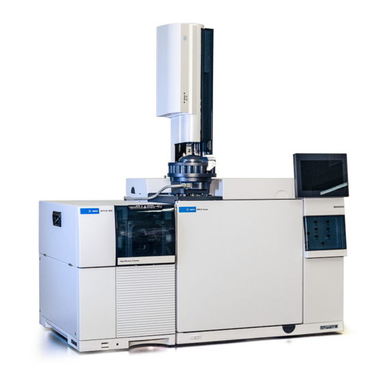
Page 17: Msd Hardware Description
GC power switch Figure 1. 5977C Series GC/MSD system, shown with an Agilent 8890 GC In this manual, the term “CI MSD” refers to the G7078B MSD or to the G7077B, G7079B, and G7081B models that were field upgraded for CI operation. It also applies, unless otherwise specified, to the flow modules for these instruments. - Page 18 Introduction MSD Hardware Description The 5977C Series CI system field upgrade adds the following to the 5977C Series MSD: • EI/CI GC/MSD interface • JetClean option that shares the same MFC system EI/CI GC/MSD interface • CI source with the new common interface tip seal that can also be used with an EI XTR source or HES •...
-
Page 19: Important Safety Warnings
Introduction Important Safety Warnings Important Safety Warnings There are several important safety notices to always keep in mind when using the MSD. Many internal parts of the MSD carry dangerous voltages If the MSD is connected to a power source, even if the power switch is off, potentially dangerous voltages exist on: •... -
Page 20: Electrostatic Discharge Is A Threat To Msd Electronics
Introduction Electrostatic discharge is a threat to MSD electronics Electrostatic discharge is a threat to MSD electronics The printed circuit boards in the MSD can be damaged by electrostatic discharge. Do not touch any of the boards unless it is absolutely necessary. If you must handle them, wear a grounded wrist strap, and take other antistatic precautions. -
Page 21: The Oil Pan Under The Foreline Pump Can Be A Fire Hazard
Introduction The oil pan under the foreline pump can be a fire hazard The insulation around the GC inlets, detectors, valve box, and the insulation WAR N IN G cups is made of refractory ceramic fibers. To avoid inhaling fiber particles, we recommend the following safety procedures: •... -
Page 22: Hydrogen Safety
Introduction Hydrogen Safety Hydrogen Safety The use of hydrogen (H ) as a GC carrier gas, detector fuel gas, or in the WAR N IN G optional JetClean system, is potentially dangerous. When using hydrogen (H ) as the carrier gas or fuel gas, be aware that WAR N IN G hydrogen can flow into the GC oven and create an explosion hazard. -
Page 23: Dangers Unique To Gc/Msd Operation
Introduction Dangers unique to GC/MSD operation Dangers unique to GC/MSD operation Hydrogen presents a number of dangers. Some are general, others are unique to GC or GC/MSD operation. Dangers include, but are not limited to: • Combustion of leaking hydrogen •... -
Page 24: Precautions
You must remove the plastic cover over the glass window on the front of a WAR N IN G 5977C Series MSD. In the unlikely event of an explosion, this cover may dislodge. You MUST make sure the top thumbscrew on the analyzer side plate is fastened WAR N IN G finger-tight. - Page 25 Introduction Precautions Failure to secure your MSD as described above greatly increases the chance WAR N IN G of personal injury in the event of an explosion. If hydrogen is plumbed to any connection on the GC or MS: WAR N IN G •...
- Page 26 Introduction Precautions GC configuration: WAR N IN G • Ensure hydrogen is configured in the firmware for all gas channels using hydrogen. An EPC that is not configured for hydrogen when hydrogen is used could affect the hydrogen safety portion of the GC. •...
- Page 27 Introduction Precautions 7 Start up the GC and MSD as normal. When using hydrogencheck the system for leaks to prevent possible fire and explosion hazards based on local Environmental Health and Safety (EHS) requirements. Always check for leaks after changing a tank or servicing the gas lines.
-
Page 28: Safety And Regulatory Certifications
This equipment has been evaluated for its suitability for use in a commercial environment. When used in a domestic environment, there is a risk of radio interference. The 5977C Series MSD is designed and manufactured under a quality system registered to ISO 9001. The 5977C Series MSD is RoHS compliant. -
Page 29: Information
Introduction Information Information The Agilent Technologies 5977C Series MSD meets the following IEC classifications: Equipment Class I, Laboratory Equipment, Installation Category II, Pollution Degree 2. This unit has been designed and tested in accordance with recognized safety standards. It is designed for use indoors. If the instrument is used in a manner not specified by the manufacturer, the protection provided by the instrument may be impaired. -
Page 30: Electromagnetic Compatibility
4 Ensure that all peripheral devices are also certified. 5 Ensure that appropriate cables are used to connect the device to peripheral equipment. 6 Consult your equipment dealer, Agilent Technologies, or an experienced technician for assistance. Changes or modifications not expressly approved by Agilent Technologies could void the user’s authority to operate the equipment. -
Page 31: Intended Use
Introduction Intended Use Intended Use Agilent products must be used only in the manner described in the Agilent product user guides. Any other use may result in damage to the product or personal injury. Agilent is not responsible for any damages caused, in whole or in part, by improper use of the products, unauthorized alterations, adjustments, or modifications to the products, failure to comply with procedures in Agilent product user guides, or use of the products in violation of applicable laws, rules,... -
Page 32: To Replace The Primary Fuses
Introduction To Replace the Primary Fuses To Replace the Primary Fuses Materials needed • Fuse, T12.5A, 250 V (2110-1398) – 2 required • Screwdriver, flat-blade (8730-0002) The most likely cause of primary fuse failure is a problem with the foreline pump. If the primary fuses in your MSD fail, check the foreline pump. - Page 33 Introduction To Replace the Primary Fuses Primary fuses in holders Figure 2. Primary fuses 6 Repeat steps through for the other fuse. Always replace both fuses. 7 Reconnect the MSD power cord to the electrical outlet. 8 Pumpdown the MSD. 5977C GC/MSD Operating Manual...
- Page 34 Introduction To Replace the Primary Fuses 5977C GC/MSD Operating Manual...
-
Page 35: Installing 8890 Gc Columns
Installing 8890 GC Columns Columns 36 To Install a Capillary Column in a Split/Splitless Inlet 38 To Condition a Capillary Column 41 To Install a Capillary Column in the GC/MSD Interface Using the Self-Tightening Column Nut 42 To Install a Capillary Column in the GC/MSD Interface Using a Standard Column Nut 47 To Install the GC/MSD Interface Tip Seal 50 The GC/MSD Interface for an 8890 Series GC 52... -
Page 36: Columns
Installing 8890 GC Columns Columns Columns Many types of GC columns can be used with the MSD, but there are some restrictions. During tuning or data acquisition, the rate of column flow into the MSD should not exceed the maximum recommended flow. Therefore, there are limits to column length, diameter, and flow. -
Page 37: Conditioning Ferrules
Tips and hints • The column installation procedures for the 5977C Series MSDs may be different from that for previous MSDs. Using the procedure from another instrument may not work, and may damage the column or the MSD. -
Page 38: To Install A Capillary Column In A Split/Splitless Inlet
Installing 8890 GC Columns To Install a Capillary Column in a Split/Splitless Inlet To Install a Capillary Column in a Split/Splitless Inlet Materials needed • Gloves, clean • Large (8650-0030) • Small (8650-0029) • Metric ruler • Wrench, open-end, 1/4-inch and 5/16-inch (8710-0510) •... - Page 39 Installing 8890 GC Columns To Install a Capillary Column in a Split/Splitless Inlet Procedure 1 Cool the oven and inlet to room temperature. 2 Wearing clean gloves, press the column through the septum (this takes a bit of pressure). Then slide the column nut and conditioned ferrule onto the free end of the column.
- Page 40 Installing 8890 GC Columns To Install a Capillary Column in a Split/Splitless Inlet Insulation cup Reducing nut The traditional inlet column nut is shown, Capillary column and the recommended 4 to 6 mm self tightening inlet Ferrule (inside nut) column nut is also provided but not shown.
-
Page 41: To Condition A Capillary Column
Installing 8890 GC Columns To Condition a Capillary Column To Condition a Capillary Column Materials needed • Carrier gas, (99.9995% pure or better) • Wrench, open-end, 1/4-inch and 5/16-inch (8710-0510) Do not condition your capillary column with hydrogen. Hydrogen accumulation WAR N IN G in the GC oven can result in an explosion. -
Page 42: To Install A Capillary Column In The Gc/Msd Interface Using The Self-Tightening Column Nut
Installing 8890 GC Columns To Install a Capillary Column in the GC/MSD Interface Using the Self-Tightening Column Nut To Install a Capillary Column in the GC/MSD Interface Using the Self-Tightening Column This procedure is for the installation of a capillary column directly into the analyzer using the Agilent recommended self-tightening column nut. - Page 43 Installing 8890 GC Columns To Install a Capillary Column in the GC/MSD Interface Using the Self-Tightening Column Nut Procedure Always wear clean gloves while handling any parts that go inside the GC or the C AU T I O N analyzer chambers.
- Page 44 Installing 8890 GC Columns To Install a Capillary Column in the GC/MSD Interface Using the Self-Tightening Column Nut 10 Adjust the column so it extends this specified distance from the end of the GC/MSD interface. For an EI XTR, SS, Inert or CI Source Installation (See Figure 5.), the column extends about 1 mm from the column guide tube.
- Page 45 Installing 8890 GC Columns To Install a Capillary Column in the GC/MSD Interface Using the Self-Tightening Column Nut 11 Hand-tighten the nut. (See Figure 7.) Ensure the position of the column does not change as you tighten the nut. Do not over tighten the nut. 12 Tighten the nut in the clockwise direction.
- Page 46 16 You can align the ion source and interface tip seal by wiggling the side plate on its hinge. If the door still will not close, contact your Agilent Technologies service representative. 17 Close the analyzer chamber door. (See “To Close the Analyzer Chamber”...
-
Page 47: To Install A Capillary Column In The Gc/Msd Interface Using A Standard Column Nut
Installing 8890 GC Columns To Install a Capillary Column in the GC/MSD Interface Using a Standard Column Nut To Install a Capillary Column in the GC/MSD Interface Using a Standard Column Nut This procedure is for the installation of a capillary column directly into the analyzer. - Page 48 Installing 8890 GC Columns To Install a Capillary Column in the GC/MSD Interface Using a Standard Column Nut Procedure Always wear clean gloves while handling any parts that go inside the GC or the C AU T I O N analyzer chambers.
- Page 49 17 You can align the ion source and interface tip seal by wiggling the side plate on its hinge. If the door still will not close, contact your Agilent Technologies service representative. 18 Close the analyzer chamber door. (See “To Close the Analyzer Chamber”...
-
Page 50: To Install The Gc/Msd Interface Tip Seal
Installing 8890 GC Columns To Install the GC/MSD Interface Tip Seal To Install the GC/MSD Interface Tip Seal Materials needed • Interface tip seal (G3870-20542) • Tip seal spring (G7005-20024) • Knurled tip seal retainer (G3870-20547) The interface tip seal must be in place for the CI source, the EI XTR source, and HES. - Page 51 5 You can align the analyzer and interface by wiggling the side plate on its hinge. If the analyzer still will not close, contact your Agilent Technologies service representative.
-
Page 52: The Gc/Msd Interface For An 8890 Series Gc
Installing 8890 GC Columns The GC/MSD Interface for an 8890 Series GC The GC/MSD Interface for an 8890 Series GC The GC/MSD interface is a heated conduit into the MSD for the capillary column. (See Figure 9.) It is bolted onto the right side of the analyzer chamber, with an O-ring seal. - Page 53 Installing 8890 GC Columns The GC/MSD Interface for an 8890 Series GC The GC/MSD interface is heated by an electric cartridge heater. Normally, the heater is powered and controlled by Thermal Aux #2 heated zone of the GC. The interface temperature can be set from Agilent MassHunter GC/MS Acquisition software or from the GC.
- Page 54 Installing 8890 GC Columns The GC/MSD Interface for an 8890 Series GC 5977C GC/MSD Operating Manual...
-
Page 55: Installing Intuvo 9000 Gc Columns
Installing Intuvo 9000 GC Columns Columns 56 To Replace an Intuvo GC Column 59 To Replace an Intuvo 9000 GC Gasket 63 To Install a Column Guard or Jumper Chip 64 To Replace the 9000 GC/MS Tail 68 To Install the GC/MSD Interface Tip Seal 74 The GC/MSD Interface for a 9000 Series GC 76 This chapter shows you how to install an Agilent Intuvo column, connect the flow path from the inlet through the guard chip, bus components, and column to the MS... -
Page 56: Columns
Installing Intuvo 9000 GC Columns Columns Columns Many types of Intuvo 9000 GC columns can be used with the MSD, but there are some restrictions. During tuning or data acquisition, the rate of column flow into the MSD should not exceed the maximum recommended flow. Therefore, there are limits to column length and flow. -
Page 57: Conditioning Columns
Installing Intuvo 9000 GC Columns Conditioning columns Conditioning columns Conditioning a column before it is connected to the GC/MSD interface is essential. A small portion of the capillary column stationary phase is often carried away by the carrier gas. This is called column bleed. Column bleed deposits traces of the stationary phase in the MSD ion source. - Page 58 Installing Intuvo 9000 GC Columns Handling the Intuvo 9000GC Column and Bus Components Handling the Intuvo 9000GC Column and Bus Components The Agilent Intuvo 9000 Gas Chromatograph (Intuvo 9000 GC) does not use traditional ferrules and nuts for most column and flow path seals. In a traditional gas chromatography connection, the seal is made by deforming a soft ferrule around the periphery of a column or tube, with a second seal made between the ferrule and the fitting.
-
Page 59: To Replace An Intuvo Gc Column
Installing Intuvo 9000 GC Columns To Replace an Intuvo GC Column To Replace an Intuvo GC Column This procedure applies to GCs with a single column. For a 2 column replacement see the Agilent Intuvo 9000 Gas Chromatograph Maintaining Your GC manual. Materials needed •... - Page 60 Installing Intuvo 9000 GC Columns To Replace an Intuvo GC Column 4 Open the GC front door. (See Figure 10.) 5 Open the bus door and remove it by lifting the door vertically off its hinge pins. 6 Lower the oven door. Bus door Oven door Intuvo torque driver...
- Page 61 Installing Intuvo 9000 GC Columns To Replace an Intuvo GC Column 7 Using the Intuvo torque driver, rotate all four column clamps off the column's retainer ring. (See Figure 11.) Click and run connectors Compression bolts Column clamps Retainer ring SmartID key Figure 11.
- Page 62 Installing Intuvo 9000 GC Columns To Replace an Intuvo GC Column 11 Replace the gasket with a new gasket rated for the maximum column temperature expected with your method. (See “To Replace an Intuvo 9000 GC Gasket” on page 63.) 12 Verify that all Intuvo gaskets in the flow path are rated for the maximum column temperature expected with your method.
-
Page 63: To Replace An Intuvo 9000 Gc Gasket
Installing Intuvo 9000 GC Columns To Replace an Intuvo 9000 GC Gasket To Replace an Intuvo 9000 GC Gasket This procedure assumes you have already removed the column, 9000 GC/MS Tail, or other part that sits on top of the gasket and that the instrument components are below 40 °C. -
Page 64: To Install A Column Guard Or Jumper Chip
Installing Intuvo 9000 GC Columns To Install a Column Guard or Jumper Chip To Install a Column Guard or Jumper Chip The column Guard Chip and the Jumper Chip are both single-use, consumable parts. Installation deforms part of the Chip to make a good seal, so that a misinstalled Chip cannot be reused. - Page 65 Installing Intuvo 9000 GC Columns To Install a Column Guard or Jumper Chip 1 Prepare the GC for maintenance. From the GC panel select Maintenance > Inlets > Guard Chip > Prepare for Maintenance >Replace Liner and Guard Chip > Start Maintenance. This procedure cools the inlet, detector, column, Guard Chip, and other components in the flow path heated zones to <...
- Page 66 Installing Intuvo 9000 GC Columns To Install a Column Guard or Jumper Chip 9 Pull the compression bolt access plate out to allow the torque driver to access the Guard chip compression bolt. (See Figure 13 on page 66.) Guard chip compression bolt Guard chip Inlet base...
- Page 67 Installing Intuvo 9000 GC Columns To Install a Column Guard or Jumper Chip Use the Intuvo torque driver to tighten the compression bolt until you hear one C AU T I O N click. Over-tightening can damage the flow path, strip the fittings, and cause leaks.
-
Page 68: To Replace The 9000 Gc/Ms Tail
Installing Intuvo 9000 GC Columns To Replace the 9000 GC/MS Tail To Replace the 9000 GC/MS Tail This procedure is necessary if you are switching to a source that requires a different 9000 GC/MS Tail, replacing a leaking gasket or a contaminated 9000 GC/MS Tail, or separating the 9000 GC from the MSD. - Page 69 Installing Intuvo 9000 GC Columns To Replace the 9000 GC/MS Tail 4 Open the analyzer chamber. (See “To Open the Analyzer Chamber” page 149.) 5 If present, unscrew the knurled tip seal retainer and remove it, the interface tip seal, and spring from the GC/MSD interface. (See “GC/MSD interface tip seal”...
- Page 70 Installing Intuvo 9000 GC Columns To Replace the 9000 GC/MS Tail 12 Remove the 9000 GC/MS Tail from the transfer line and bus. (See Figure 15 Figure 16.) If the ferrule becomes stuck, press a pointed object, like a paper clip, into the ferrule release hole at the end of the transfer line.
- Page 71 26 You can align the ion source and interface tip seal by wiggling the side plate on its hinge. If the door still will not close, contact your Agilent Technologies service representative. 27 Close the analyzer chamber. (See “To Close the Analyzer Chamber”...
-
Page 72: To Condition An Intuvo Capillary Column
Installing Intuvo 9000 GC Columns To Condition an Intuvo Capillary Column To Condition an Intuvo Capillary Column Materials needed • Carrier gas, (99.9995% pure or better) • Gloves, clean, lint-free • Large (8650-0030) • Small (8650-0029) • Tweezers (8710-2460) • Intuvo torque driver (5190-9571) •... - Page 73 Installing Intuvo 9000 GC Columns To Condition an Intuvo Capillary Column 6 Program the column temperature to increase from 120 °C to the maximum temperature limit for the column at a rate of 10 to 15 °C/min. Never exceed the maximum column temperature, in the GC/MSD interface, C AU T I O N the GC oven, or the inlet.
-
Page 74: To Install The Gc/Msd Interface Tip Seal
Installing Intuvo 9000 GC Columns To Install the GC/MSD Interface Tip Seal To Install the GC/MSD Interface Tip Seal Materials needed • Interface tip seal (G3870-20542) • Tip seal spring (G7005-20024) • Knurled tip seal retainer (G3870-20547) The interface tip seal must be in place for the CI source, the EI XTR source, and HES. - Page 75 5 You can align the analyzer and interface by wiggling the side plate on its hinge. If the analyzer still will not close, contact your Agilent Technologies service representative.
-
Page 76: The Gc/Msd Interface For A 9000 Series Gc
Installing Intuvo 9000 GC Columns The GC/MSD Interface for a 9000 Series GC The GC/MSD Interface for a 9000 Series GC The GC/MSD Interface is a heated conduit into the MSD for maintaining MSD vacuum and a suitable column effluent temperature. (See Figure 18.) The GC/MSD Interface is bolted onto the right side of the analyzer chamber, with an... -
Page 77: Operating In Ei Mode
To Perform High-Mass Testing 105 To Open the MSD Covers 108 To Vent the MSD 109 To Pumpdown the MSD 112 This chapter describes how to perform some basic operating procedures for the Agilent 5977C Series GC/MSD using EI. 5977C GC/MSD Operating Manual... - Page 78 Operating in EI Mode If you are using the Agilent Intuvo 9000 Gas Chromatograph with your MSD, Chemical Ionization (CI) is not currently supported. 5977C GC/MSD Operating Manual...
-
Page 79: Operating The Msd From The Ds
Operating in EI Mode Operating the MSD from the DS Operating the MSD from the DS The Agilent MassHunter GC/MS Acquisition software automates tasks such as pumping down, monitoring settings, setting temperatures, tuning, and venting the MSD. These tasks are described in this chapter. Additional information is described in the manuals and online help supplied with the Agilent MassHunter GC/MS Acquisition software. -
Page 80: Configuring The Msd Through The Web User Interface (Wui)
Operating in EI Mode Configuring the MSD through the Web User Interface (WUI) Configuring the MSD through the Web User Interface (WUI) If your GC does not support LVDS communications with an Agilent GC, you can use the WUI to configure the MSD network settings. Reasons that a GC does not support configuring a 5977C MSD’s network settings from the GC control panel include any of the following: •... - Page 81 Operating in EI Mode To change the network settings of the MSD 4 Enter the IP address into a PC web browser URL to display the WUI page. (See Figure 19.) Figure 19. WUI main menu 5 Click Set Real-Time Clock or Edit NetConfig, and go to Edit NetConfig (MSD network configuration).
- Page 82 Operating in EI Mode To change the network settings of the MSD 6 Confirm that BootP is set to OFF. If your LAN assigns IP addresses using a BootP server, click ON and skip the next step. 7 To update the MSD IP address, Gateway IPA, and SubNet Mask enter the new values.
-
Page 83: Emodule Mini Display Readout
Operating in EI Mode eModule Mini Display Readout eModule Mini Display Readout The eModule mini display, accessible when the analyzer door cover is open, allows the operator to view the LAN configuration of the instrument including its IP address, subnet mask, default gateway, and MAC address. This LAN configuration can be changed using the GC control panel or the web user interface (WUI) from a web browser. -
Page 84: Front Panel Instrument Status Led
Operating in EI Mode Front Panel Instrument Status LED Front Panel Instrument Status LED Through the front panel instrument status LED, the operator can view the current status of the instrument using color codes and LED on/off timing. (See Table Table 7 Front panel Instrument Status LED codes Instrument status... -
Page 85: Before You Turn On The Msd
Operating in EI Mode Before You Turn On the MSD Before You Turn On the MSD Verify the following before you turn on or attempt to operate the MSD. • The vent valve should be open slightly (knob turned 45 degrees counterclockwise from the fully closed position). -
Page 86: Pumping Down
Operating in EI Mode Pumping Down Pumping Down The DS or 8890 or 9000 GC control panels help you pumpdown the MSD. The process is primarily automated. After you turn on the MSD by pressing the On/Off switch, close the analyzer door, and close the vent valve once you hear hissing (while pressing on the sideplate). -
Page 87: Controlling Column Flow
Operating in EI Mode Controlling Column Flow Controlling Column Flow Carrier gas flow is controlled by inlet pressure in the GC. Set the column mode to Constant Pressure to maintain a constant inlet pressure, and the column flow will decrease as the GC oven temperature increases. With EPC and the column mode set to Constant Flow, the same column flow is maintained regardless of temperature. -
Page 88: Venting The Msd
Operating in EI Mode Venting the MSD Venting the MSD The DS guides you through the venting process. It turns off the GC and MSD heaters and diffusion pump heater or the turbo pump at the correct time. It also lets you monitor temperatures in the MSD and indicates when to vent the MSD. -
Page 89: To View Msd Temperature And Vacuum In Manual Tune
Operating in EI Mode To View MSD Temperature and Vacuum in Manual Tune To View MSD Temperature and Vacuum in Manual Tune You can also use the GC touchscreen to perform this task. Procedure 1 In Instrument Control view, select Edit Tune Parameters from the Instrument menu to display the Manual Tune dialog. - Page 90 Operating in EI Mode To View MSD Temperature and Vacuum in Manual Tune Figure 24. HES manual tune values tab 3 To change a temperature Setpoint or Limit enter the new parameters and click Apply. Temperature setpoints or limits can not be changed until the foreline pressure is less than 300 mTorr, or the turbo pump is running at least 80% speed.
-
Page 91: To Set Monitors For Msd Temperature And Vacuum Status
Operating in EI Mode To Set Monitors for MSD Temperature and Vacuum Status To Set Monitors for MSD Temperature and Vacuum Status A monitor displays the current value of a single instrument parameter. They can be added to the standard instrument control window. Monitors can be set to change color if the actual parameter varies beyond a user-determined limit from its setpoint. - Page 92 Operating in EI Mode To Set Monitors for MSD Temperature and Vacuum Status 2 In the Available Monitors column, select a monitor, and click Add to move the selection to the Selected Monitors column. Repeat for additional monitors. 3 Click OK. At the Arrange Monitors prompt, click Yes to have the monitors automatically arranged on the Instrument panel.
- Page 93 Operating in EI Mode To Set Monitors for MSD Temperature and Vacuum Status 5 To set a monitor’s alarm, double-click a monitor displayed in the Instrument Control view to open that monitor’s dialog for setting alarms. (See Figure 27.) Figure 27 Monitor’s alarm settings a Select the Set Alarm check box.
-
Page 94: To Set Analyzer Temperatures From The Instrument Control View
Operating in EI Mode To Set Analyzer Temperatures from the Instrument Control View To Set Analyzer Temperatures from the Instrument Control View MSD ion source and Quad temperatures are stored in the current tune (*.u) file. When a method is loaded, the setpoints in the tune file associated with that method are downloaded automatically. - Page 95 Operating in EI Mode To Set Analyzer Temperatures from the Instrument Control View 3 To send the new temperature parameters to the currently loaded tune file and download these parameters to the MSD, click Apply. 4 Click Close to exit the dialog. If changes were made to any parameters the Save MS Tune File dialog displays.
-
Page 96: To Set The Gc/Msd Interface Temperature From Masshunter
Operating in EI Mode To Set the GC/MSD Interface Temperature from MassHunter To Set the GC/MSD Interface Temperature from MassHunter Procedure 1 From Instrument Control view select Instrument > GC Parameters. 2 Click Aux Heaters to edit the interface temperature. (See Figure 29.) Figure 29... - Page 97 Operating in EI Mode To Set the GC/MSD Interface Temperature from MassHunter Ensure that the carrier gas is turned on and the column has been purged of air C AU T I O N before heating the GC/MSD interface or the GC oven. When setting the GC/MSD interface temperature, never exceed the maximum for your column.
-
Page 98: To Monitor High Vacuum Pressure
Operating in EI Mode To Monitor High Vacuum Pressure To Monitor High Vacuum Pressure Pressure monitoring requires an optional G3397B Micro-Ion vacuum gauge. If you are using hydrogen as a carrier gas or for the JetClean system, the WAR N IN G hydrogen gas flow must be off before turning off the MSD power. - Page 99 Operating in EI Mode To Monitor High Vacuum Pressure The largest influence on operating pressure in EI mode is the carrier gas (column) flow. Table 9 lists typical pressures for various helium carrier gas flows. These pressures are approximate and will vary from instrument to instrument by as much as 30%.
-
Page 100: To Tune The Msd In Ei Mode
Operating in EI Mode To Tune the MSD in EI Mode To Tune the MSD in EI Mode Procedure 1 Load the method that will be used for data acquisition. 2 In the Instrument Control view, verify the correct tune file is displayed in the tile bar. - Page 101 Operating in EI Mode To Tune the MSD in EI Mode 7 Wait for the tune to complete, and generate the report. 8 To evaluate the tune results, select Evaluate Tune from the Checkout menu in Instrument Control view. To view history of tune results, in the Instrument Control view select Checkout>View Previous Tunes..
-
Page 102: To Set The Operation Mode For The Optional Jetclean System
Operating in EI Mode To Set the Operation Mode for the Optional JetClean System To Set the Operation Mode for the Optional JetClean System Procedure: 1 In Instrument Control view, click the MS Parameters icon. 2 In the Single Quadrupole MS Method Editor navigation panel, select the JetClean tab. -
Page 103: To Set The Jetclean Parameters For The Clean Only Mode
Operating in EI Mode To Set the JetClean Parameters for the Clean Only Mode To Set the JetClean Parameters for the Clean Only Mode Procedure: 1 In Instrument Control view, click the MS Parameters icon. 2 In the Single Quadrupole MS Method Editor, select the JetClean tab. (See Figure 33.) 3 From the Operation dropdown menu, select Clean Only. -
Page 104: To Verify Ei System Performance
Operating in EI Mode To Verify EI System Performance To Verify EI System Performance Materials needed for an EI HES • 10 fg/µL OFN Checkout standard 3 × 1 mL (5190-0585) Materials needed for an EI XTR, SS, or Inert source •... -
Page 105: To Perform High-Mass Testing
Operating in EI Mode To Perform High-Mass Testing To Perform High-Mass Testing Materials needed • PFHT High Mass checkout sample 3 × 1 mL (5188-5357) Procedure 1 Load the autotune file (atune.u, HES_atune.u, etune.u) then auto tune the MSD. (See “To Tune the MSD in EI Mode”... - Page 106 Operating in EI Mode To Perform High-Mass Testing Figure 34. PFHT high mass report 5977C GC/MSD Operating Manual...
- Page 107 Operating in EI Mode To Perform High-Mass Testing Results Results will indicate the recommended amount to adjust AMU offset for high mass. If your results are within 5 units of the targeted amount, there is no need to make adjustments. Adjustments 1 Verify the autotune file (atune.u, HES_atune.u, etune.u) has been loaded.
-
Page 108: To Open The Msd Covers
Operating in EI Mode To Open the MSD Covers To Open the MSD Covers If you need to open one of the MSD covers, follow these procedures. To remove the analyzer window cover Press down on the rounded area on the top of the window, tilt the window slightly forward and lift it off the MSD. -
Page 109: To Vent The Msd
Operating in EI Mode To Vent the MSD To Vent the MSD Agilent MassHunter GC/MS Acquisition software allows you to specify parameters in a GC method that will automate and speed up the vent process if direct communication (DCOMM) with the GC is established. You must predefine a Fast Vent method to use this option. - Page 110 Operating in EI Mode To Vent the MSD 2 In the Instrument Control view, Instrument menu, select MS Vacuum Control to display the Vacuum Control dialog. (See Figure 36 on page 110.) Figure 36 Vacuum control dialog 3 Remove the analyzer window cover. (See “To Open the MSD Covers”...
- Page 111 Operating in EI Mode To Vent the MSD Never open the vent valve without first closing the hydrogen supply line to all possible WAR N IN G sources of hydrogen entry to the analyzer. This requires closing the hydrogen shutoff valve to the carrier gas flow module and the shutoff valve to the JetClean system supply if either of these hydrogen sources exist on the instrument.
-
Page 112: To Pumpdown The Msd
Operating in EI Mode To Pumpdown the MSD To Pumpdown the MSD You can also use the 8890 or 9000 GC touchscreen to perform this task. Make sure your MSD meets all the conditions listed in the introduction to this WAR N IN G chapter before starting up and pumping down the MSD. - Page 113 Operating in EI Mode To Pumpdown the MSD 4 Open the vent valve by turning it counterclockwise 45 degrees. (See Figure 38.) Vent valve knob Figure 38 Vent valve knob 5 Verify that the MSD power cord is plugged into a grounded building’s main receptacle.
- Page 114 Operating in EI Mode To Pumpdown the MSD 10 In the Instrument Control view, from the Instrument menu, select MS Vacuum Control to display the Vacuum Control dialog. (See Figure 39.) Figure 39 Vacuum Control dialog 11 Click Pump Down in the Vacuum Control dialog, and follow the system prompts.
-
Page 115: Operating In Ci Mode
To Verify NCI Performance 136 To Monitor CI Mode High Vacuum Pressure 137 This chapter provides information and instructions for operating the 5977C Series CI MSDs in CI mode. Most of the information in the preceding chapter is also relevant. -
Page 116: General Guidelines
Operating in CI Mode General Guidelines General Guidelines • Always use the highest purity methane (and other reagent gases, if applicable). Methane must be at least 99.9995% pure. • Always verify the MSD is performing well in EI mode before switching to CI. (See “To Verify EI System Performance”... -
Page 117: Ci Autotune
Operating in CI Mode CI Autotune CI Autotune After the reagent gas flow is adjusted, the lenses and electronics of the MSD should be tuned. (See Table 10 on page 118.) Perfluoro-5,8-dimethyl-3,6,9-trioxidodecane (PFDTD) is used as the calibrant. Instead of flooding the entire vacuum chamber, the PFDTD is introduced directly into the ionization chamber through the GC/MSD interface by means of the gas flow control module. - Page 118 Operating in CI Mode CI Autotune Table 10 Reagent gas settings Reagent gas Methane Isobutane Ammonia Ion polarity Positive Negative Positive Negative Positive Negative 150 A 50 A 150 A 50 A 150 A 50 A 35 A Emission Electron energy 150 eV 150 eV 150 eV...
-
Page 119: To Operate The Ci Msd
Operating in CI Mode To Operate the CI MSD To Operate the CI MSD Operating your MSD in the CI mode is slightly more complicated than operating in the EI mode. After tuning, gas flow, source temperature, and electron energy may need to be optimized for your specific analyte. -
Page 120: To Pumpdown The Msd In Ci Mode
Operating in CI Mode To Pumpdown the MSD in CI Mode To Pumpdown the MSD in CI Mode This procedure assumes that the instrument will eventually be PCI tuned using methane after the system is stable. Procedure 1 Follow the instructions for the EI MSD. ( “To Pumpdown the MSD”... -
Page 121: To Set Up The Software For Ci Operation
Operating in CI Mode To Set Up the Software for CI Operation To Set Up the Software for CI Operation Always verify GC/MSD performance in EI before switching to CI operation. C AU T I O N Procedure 1 From the Tune and Vacuum Control view, select Load Tune Parameters from the File menu, and load the tune file PCICH4.U. - Page 122 Operating in CI Mode To Set Up the Software for CI Operation • Ion polarity: Always set up in PCI with methane first, then switch to your desired ion polarity and reagent gas. • Abundance target: Adjust higher or lower to get the desired signal abundance.
-
Page 123: To Operate The Reagent Gas Flow Control Module
Operating in CI Mode To Operate the Reagent Gas Flow Control Module To Operate the Reagent Gas Flow Control Module After the system has been switched from EI to CI mode, or vented for any other C AU T I O N reason, the MSD must be baked out for at least 2 hours before tuning. - Page 124 Operating in CI Mode To Operate the Reagent Gas Flow Control Module 2 In the Operations area, select admit a reagent gas for the current tune file. The system evacuates the gas lines for 6 minutes, then turns on the selected gas (A or B).
- Page 125 Operating in CI Mode To Operate the Reagent Gas Flow Control Module source Gas A (methane) supply Shutoff Gas A valve select valve Gas B select valve GC/MSD Calibration Gas B interface valve (other) supply Restrictor Calibration GC column vial Figure 41.
-
Page 126: To Set Up Methane Reagent Gas Flow
Operating in CI Mode To Set Up Methane Reagent Gas Flow To Set Up Methane Reagent Gas Flow The reagent gas flow must be adjusted for maximum stability before tuning the CI system. Do the initial setup with methane in PCI mode. No flow adjustment procedure is available for NCI, as no negative reagent ions are formed. - Page 127 Operating in CI Mode To Set Up Methane Reagent Gas Flow 8 Examine the displayed profile scan of the reagent ions. (See Figure 42.) • There should be no visible peak at m/z 32. A peak there indicates an air leak.
-
Page 128: To Use Other Reagent Gases
Changing the reagent gas from methane to either isobutane or ammonia changes the chemistry of the ionization process and yields different ions. The principal CI reactions encountered are described in general in the 5977C Series Concepts Guide. If you are not experienced with CI, we suggest reviewing that material before you proceed. - Page 129 Operating in CI Mode To Use Other Reagent Gases Isobutane CI Isobutane (C ) is commonly used for CI when less fragmentation is desired in the CI spectrum. This is because the proton affinity of isobutane is higher than that of methane; hence, less energy is transferred in the ionization reaction. Addition and proton transfer are the ionization mechanisms most often associated with isobutane.
- Page 130 Ammonia tends to break down vacuum pump fluids and seals. Ammonia CI makes more frequent vacuum system maintenance necessary. Refer to the Agilent 5977C Series MSD Troubleshooting and Maintenance Manual. Frequently, a mixture of 5% ammonia and 95% helium or 5% ammonia and 95% methane is used as a CI reagent gas.
-
Page 131: To Perform A Pci Autotune (Methane Only)
Operating in CI Mode To Perform a PCI Autotune (Methane Only) To Perform a PCI Autotune (Methane Only) Always verify MSD performance in EI before switching to CI operation. Always C AU T I O N set up the CI MSD in PCI first, even if you are going to run NCI. Avoid tuning more often than is absolutely necessary;... - Page 132 Operating in CI Mode To Perform a PCI Autotune (Methane Only) Figure 43. PCI autotune report 5977C GC/MSD Operating Manual...
-
Page 133: To Perform An Nci Autotune (Methane Reagent Gas)
Operating in CI Mode To Perform an NCI Autotune (Methane Reagent Gas) To Perform an NCI Autotune (Methane Reagent Gas) Always verify MSD performance in EI before switching to CI operation. (See C AU T I O N “To Verify EI System Performance” on page 104.) Always set up the CI MSD in PCI with methane as the reagent gas first, even if you are going to be using a different reagent gas or going to run NCI. - Page 134 Operating in CI Mode To Perform an NCI Autotune (Methane Reagent Gas) Figure 44. NCI autotune 5977C GC/MSD Operating Manual...
-
Page 135: To Verify Pci Performance
Operating in CI Mode To Verify PCI Performance To Verify PCI Performance Materials needed • Benzophenone, 100 pg/L 5 × 1 mL (8500-5440) Always verify MSD performance in EI before switching to CI operation. (See C AU T I O N “To Verify EI System Performance”... -
Page 136: To Verify Nci Performance
Operating in CI Mode To Verify NCI Performance To Verify NCI Performance This procedure is for EI/PCI/NCI MSDs only. Materials needed • OFN, 100 fg/µL 3 × 1 mL (5188-5347) Always verify MSD performance in EI before switching to CI operation. (See C AU T I O N “To Verify EI System Performance”... -
Page 137: To Monitor Ci Mode High Vacuum Pressure
Operating in CI Mode To Monitor CI Mode High Vacuum Pressure To Monitor CI Mode High Vacuum Pressure If hydrogen is used as a carrier gas or JetClean system supply, the carrier and WAR N IN G JetClean system supply shutoff valves must be closed before turning off the MSD power. - Page 138 Operating in CI Mode To Monitor CI Mode High Vacuum Pressure Table 15 MFC settings and typical pressure readings Pressure (Torr) Methane Ammonia EI/PCI/NCI MSD EI/PCI/NCI MSD (Turbo pump) (Turbo pump) –5 –5 10 × × –5 –5 10 × ×...
-
Page 139: General Maintenance
General Maintenance Before Starting 141 Maintaining the Vacuum System 146 Maintaining the Analyzer 147 To Open the Analyzer Chamber 149 To Remove the EI HES 151 To Connect/Disconnect Wiring to the EI HES 153 To Disassemble the EI HES 154 To Clean the EI HES 157 To Assemble the EI HES 160 To Remove the EI HES Filaments 165... - Page 140 General Maintenance To Replace the Electron Multiplier Horn 200 To Close the Analyzer Chamber 202 If you are using the Agilent Intuvo 9000 Gas Chromatograph with your MSD, Chemical Ionization (CI) and the JetClean system are not currently supported. 5977C GC/MSD Operating Manual...
-
Page 141: Before Starting
General Maintenance Before Starting Before Starting You can perform much of the maintenance required by your MSD. For your safety, read all of the information in this introduction before performing any maintenance tasks. Scheduled maintenance Performing the common maintenance tasks when scheduled can reduce operating problems, prolong system life, and reduce overall operating costs. - Page 142 General Maintenance Before Starting Keep a record of system performance (tune reports) and maintenance operations performed. This makes it easier to identify variations from normal operation and to take corrective action. Tools, spare parts, and supplies Some of the required tools, spare parts, and supplies are included in the GC shipping kit, MSD shipping kit, or MSD tool kit.
- Page 143 General Maintenance Before Starting Dangerous temperatures Many parts in the MSD operate at, or reach, temperatures high enough to cause serious burns. These parts include, but are not limited to: • GC inlet • GC oven and its contents • GC detector •...
- Page 144 General Maintenance Before Starting install a hose to take the exhaust from the foreline pump outdoors or into a fume hood vented to the outdoors. For the standard foreline pump, this requires removing the oil trap. Be sure to comply with your local air quality regulations. The oil trap supplied with the standard foreline pump stops only foreline pump WAR N IN G oil.
- Page 145 General Maintenance Before Starting When you work on or near printed circuit boards or when you work on components with wires, contacts, or cables connected to printed circuit boards, always use a grounded antistatic wrist strap and take other antistatic precautions.
-
Page 146: Maintaining The Vacuum System
Other procedures Tasks such as replacing a foreline vacuum gauge or Micro-Ion vacuum gauge should be performed only when needed. Refer to the Agilent 5977C Series MSD Troubleshooting and Maintenance manual and the online help in Agilent MassHunter GC/MS Acquisition software for symptoms that indicate this type of maintenance is required. -
Page 147: Maintaining The Analyzer
Replacing filaments • Replacing the electron multiplier horn The Agilent 5977C Series MSD Troubleshooting and Maintenance Manual provides information about symptoms that indicate the need for analyzer maintenance. The troubleshooting material in the online help in the Agilent MassHunter GC/MS Acquisition software provides more extensive information. - Page 148 More information is available If you need more information about the locations or functions of analyzer components, refer to the Agilent 5977C Series MSD Troubleshooting and Maintenance Manual. Many procedures in this chapter are illustrated with video clips.
-
Page 149: To Open The Analyzer Chamber
General Maintenance To Open the Analyzer Chamber To Open the Analyzer Chamber The analyzer chamber should only be opened to clean or replace the ion source, change the detector’s EM, or to change a filament. Materials needed • Gloves, clean, lint-free •... - Page 150 General Maintenance To Open the Analyzer Chamber The bottom thumbscrew on the analyzer side plate should be unfastened during normal use. It is only fastened during shipping. The top thumbscrew on the front side plate should only be fastened if hydrogen or other flammable or toxic substances are used for carrier gas, or during CI operation.
-
Page 151: To Remove The Ei Hes
General Maintenance To Remove the EI HES To Remove the EI HES Materials needed • Gloves, clean, lint-free • Large (8650-0030) • Small (8650-0029) • Tweezers (8710-2460) Procedure 1 Vent the MSD. (See “To Vent the MSD” on page 109.) The analyzers, GC/MSD interface, and other components in the analyzer WAR N IN G chamber operate at very high temperatures. - Page 152 General Maintenance To Remove the EI HES 5 Using the source finger grip, pull the ion source out of the source radiator. The source contacts have spring loaded pins so some force must be applied to pull the source out. Ion source Thumbscrew Ceramic source board...
-
Page 153: To Connect/Disconnect Wiring To The Ei Hes
General Maintenance To Connect/Disconnect Wiring to the EI HES To Connect/Disconnect Wiring to the EI HES Materials needed • Gloves, clean, lint-free • Large (8650-0030) • Small (8650-0029) • Pliers, long-nose (8710-1094) • Tweezers (8710-2460) Procedure 1 Use tweezers or needle nose pliers to connect/disconnect the ceramic board wire leads (red, white, black, and gray) at the source connectors. -
Page 154: To Disassemble The Ei Hes
General Maintenance To Disassemble the EI HES To Disassemble the EI HES Materials needed • Gloves, clean, lint-free • Large (8650-0030) • Small (8650-0029) • Cloths, clean (05980-60051) • T6 Torx driver, (8710-2548) • Tweezers (8710-2460) Procedure Refer to the exploded parts view Figure 48 and the EI HES parts list Table 17... - Page 155 General Maintenance To Disassemble the EI HES 9 If necessary, use gravity to remove the lens stack ceramic insulator from the source body. Use care when removing the lenses from the lens insulator casing. Putting C AU T I O N excessive stress on this casing can break or crack it.
- Page 156 General Maintenance To Disassemble the EI HES Table 17 Parts list for EI HES (Figure 48) (continued) Item number Item description Part number (XTR) Ceramic insulator for extractor G7002-20064 Entrance lens assembly, Extended, HES (1)* G7004-20065 Ion focus lens (2)* G7004-20068 Lens insulator/holder G7002-20074...
-
Page 157: To Clean The Ei Hes
General Maintenance To Clean the EI HES To Clean the EI HES Materials needed • Abrasive paper (5061-5896) • Alumina abrasive powder (393706201) • Aluminum foil, clean • Cloths, clean (05980-60051) • Cotton swabs (5080-5400) • Glass beakers, 500 mL •... - Page 158 General Maintenance To Clean the EI HES These are the parts that contact the sample or ion beam. The other parts normally should not require cleaning. If insulators are dirty, clean them with a cotton swab dampened with C AU T I O N reagent-grade methanol.
- Page 159 General Maintenance To Clean the EI HES 4 Abrasively clean the surfaces that contact the sample or ion beam. Use an abrasive slurry of alumina powder and reagent-grade methanol on a cotton swab. Use enough force to remove all discolorations. Polishing the parts is not necessary;...
-
Page 160: To Assemble The Ei Hes
General Maintenance To Assemble the EI HES To Assemble the EI HES Materials needed • Gloves, clean, lint-free • Large (8650-0030) • Small (8650-0029) • T6 Torx driver, (8710-2548) • Tweezers (8710-2460) Procedure Always wear clean gloves when working in the analyzer chamber to avoid C AU T I O N contamination. - Page 161 General Maintenance To Assemble the EI HES Grooves aligned Figure 50 Assembled EI HES lens stack 2 Insert the extractor ceramic insulator into the source body. The ceramic insulator must be positioned flat against the source body when C AU T I O N inserting the lens stack in the next step.
- Page 162 General Maintenance To Assemble the EI HES Figure 51 Secure the lens screw and lock ring insulator 5 Place the heater/sensor assembly over the guide pins on the source body with the four electrical pins oriented down the flat side of the source body. 6 Place the repeller onto the heater/sensor assembly with the flat side of the repeller circumference aligned with the interface socket in the source body.
- Page 163 General Maintenance To Assemble the EI HES Figure 52 Assembling the EI HES Table 18 Parts list for EI HES (Figure Item number Item description Part number (XTR) Source finger grip G7002-20008 Filament block G7002-20019 Extractor lens (5)*, with 3 mm opening G7004-20061 Ceramic insulator for extractor G7002-20064...
- Page 164 General Maintenance To Assemble the EI HES Table 18 Parts list for EI HES (Figure 52) (continued) Item number Item description Part number (XTR) Post extractor lens 2 (3)* G7004-20090 Post extractor lens 1 (4)* G7004-20004 M2 x 6 mm gold plated screw G7002-20109 Locking ring lens insulator G7002-20126...
-
Page 165: To Remove The Ei Hes Filaments
General Maintenance To Remove the EI HES Filaments To Remove the EI HES Filaments Materials needed • Gloves, clean, lint-free • Large (8650-0030) • Small (8650-0029) • Cloths, clean (05980-60051) • T6 Torx driver, (8710-2548) Procedure 1 Vent the MSD. (See “To Vent the MSD”... - Page 166 General Maintenance To Remove the EI HES Filaments 5 Use the hand grip on the filament block to remove the filament block from the source. Use extra caution when removing the dual filament, as it is extremely brittle. C AU T I O N 6 Remove the dual filament from the filament block by lifting the source body up off of the filament block, while holding the filament block so that the dual filament will not fall and become damaged.
-
Page 167: To Install The Ei Hes Filament
General Maintenance To Install the EI HES Filament To Install the EI HES Filament Materials needed • Filament assembly, high efficiency dual filament (G7001-60001) • Hex ball driver, 1.5 mm (8710-1570) • Gloves, clean, lint-free • Large (8650-0030) • Small (8650-0029) •... -
Page 168: To Install The Ei Hes
General Maintenance To Install the EI HES To Install the EI HES Materials needed • Gloves, clean, lint-free • Large (8650-0030) • Small (8650-0029) • Tweezers (8710-2460) Procedure Always wear clean gloves when working in the analyzer chamber to avoid C AU T I O N contamination. -
Page 169: To Remove The Ei Xtr, Ss, Inert, Or HydroNert Source
General Maintenance To Remove the EI XTR, SS, Inert, or Hydronert Source To Remove the EI XTR, SS, Inert, or Hydronert Source Materials needed • Gloves, clean, lint-free • Large (8650-0030) • Small (8650-0029) • Pliers, long-nose (8710-1094) Procedure 1 Vent the MSD. -
Page 170: To Connect/Disconnect Wiring From The Ei Xtr, Ss, And Inert Sources
General Maintenance To Connect/Disconnect Wiring from the EI XTR, SS, and Inert Sources To Connect/Disconnect Wiring from the EI XTR, SS, and Inert Sources Materials needed • Gloves, clean, lint-free • Large (8650-0030) • Small (8650-0029) • Pliers, long-nose (8710-1094) •... -
Page 171: To Connect/Disconnect Wiring From The Ei Hydro Nert Source
General Maintenance To Connect/Disconnect Wiring from the EI Hydronert Source To Connect/Disconnect Wiring from the EI Hydronert Source Materials needed • Gloves, clean, lint-free • Large (8650-0030) • Small (8650-0029) • Pliers, long-nose (8710-1094) • Tweezers (8710-2460) Procedure 1 Use tweezers or needle nose pliers to connect/disconnect the ceramic source board wire leads at the source connectors. -
Page 172: To Disassemble The Ei Ss Or Ei Inert Source
General Maintenance To Disassemble the EI SS or EI Inert Source To Disassemble the EI SS or EI Inert Source Materials needed • Gloves, clean, lint-free • Large (8650-0030) • Small (8650-0029) • Hex ball driver, 1.5 mm (8710-1570) • Hex ball driver, 2.0 mm (8710-1804) •... - Page 173 General Maintenance To Disassemble the EI SS or EI Inert Source 14 14 15 15 16 16 Figure 56. Disassembling the EI SS or Inert source Table 19 Parts list for the EI SS or Inert source (Figure Item number Item description Part number (SS) Part number (Inert)
- Page 174 General Maintenance To Disassemble the EI SS or EI Inert Source Table 19 Parts list for the EI SS or Inert source (Figure 56) (continued) Item number Item description Part number (SS) Part number (Inert) Flat washer 3050-0982 3050-0982 Lens insulator G3170-20530 G3170-20530 Entrance lens...
-
Page 175: To Disassemble The Ei Xtr Source
General Maintenance To Disassemble the EI XTR Source To Disassemble the EI XTR Source Materials needed • Gloves, clean, lint-free • Large (8650-0030) • Small (8650-0029) • Hex ball driver, 1.5 mm (8710-1570) • Hex ball driver, 2.0 mm (8710-1804) •... - Page 176 General Maintenance To Disassemble the EI XTR Source Figure 57. Disassembling the EI XTR source Table 20 Parts list for EI XTR source (Figure Item Description Part number Setscrews G3870-20446 Screws G3870-20021 Source body G3870-20440 Extractor lens G3870-20444 Extractor lens insulator G3870-20445 Filaments G7005-60061...
- Page 177 General Maintenance To Disassemble the EI XTR Source Table 20 Parts list for EI XTR source (Figure 57) (continued) Item Description Part number Lens insulator G3870-20530 Entrance lens assembly, Extended G7000-20026 Ion focus lens 05971-20143 Repeller insulator G1099-20113 Repeller G3870-60171 Flat washer 3050-0891 Belleville spring washer...
-
Page 178: To Disassemble The Ei HydroNert Source
General Maintenance To Disassemble the EI Hydronert Source To Disassemble the EI Hydronert Source Materials needed • Gloves, clean, lint-free • Large (8650-0030) • Small (8650-0029) • Hex ball driver, 1.5 mm (8710-1570) • Hex ball driver, 2.0 mm (8710-1804) •... - Page 179 General Maintenance To Disassemble the EI Hydronert Source Figure 58. Disassembling the EI Hydronert source Table 21 Parts list for EI Hydronert source (Figure Item Description Part number Setscrews G3870-20446 Screws G3870-20021 Source body G7078-20903 Extractor lens, 9 mm G7078-20909 Extractor lens insulator G3870-20445 Filaments...
- Page 180 General Maintenance To Disassemble the EI Hydronert Source Table 21 Parts list for EI Hydronert source (Figure 58) (continued) Item Description Part number Lens insulator G3870-20530 Entrance lens assembly, G7078-20904 Ion focus lens G7078-20905 Repeller insulator G1099-20133 Repeller G7078-20902 Flat washer 3050-0891 Belleville spring washer 3050-1301...
-
Page 181: To Clean An Ei Xtr, Ss, Or Inert Source
General Maintenance To Clean an EI XTR, SS, or Inert Source To Clean an EI XTR, SS, or Inert Source Materials needed • Abrasive paper (5061-5896) • Alumina abrasive powder (8660-0791) • Aluminum foil, clean • Cloths, clean (05980-60051) • Cotton swabs (5080-5400) •... - Page 182 General Maintenance To Clean an EI XTR, SS, or Inert Source 3 Collect the following parts to be cleaned for an EI XTR source: (See Figure 59 on page 183.) • Repeller • Repeller block insert • Source body • Extractor lens •...
- Page 183 General Maintenance To Clean an EI XTR, SS, or Inert Source EI SS or EI Inert source parts to be cleaned Interface Drawout Repeller Repeller Entrance Ion focus Drawout Source body socket plate block insert lens lens cylinder EI XTR source parts to be cleaned Repeller Repeller Entrance...
- Page 184 General Maintenance To Clean an EI XTR, SS, or Inert Source Procedure The filaments, source heater assembly, and insulators cannot be cleaned C AU T I O N ultrasonically. Replace these components if major contamination occurs. 1 If the contamination is serious, such as an oil backflow into the analyzer, seriously consider replacing the contaminated parts.
-
Page 185: To Clean The Ei HydroNert Source
General Maintenance To Clean the EI Hydronert Source To Clean the EI Hydronert Source Do not abrasively clean the coated parts of the source. Abrasives will destroy C AU T I O N the coating and require a new part to be purchased. Replacement of Hydronert source parts is recommended if a reduction in sensitivity is observed that cannot be recovered by performing maintenance on the GCMS system. - Page 186 General Maintenance To Clean the EI Hydronert Source Figure 60. Cleaning the EI Hydro nert source Table 22 Parts list for EI Hydronert source (Figure Item Description Part number Setscrews G3870-20446 Screws G3870-20021 Source body G7078-20903 Extractor lens, 9 mm G7078-20909 Extractor lens insulator G3870-20445...
- Page 187 General Maintenance To Clean the EI Hydronert Source Table 22 Parts list for EI Hydronert source (Figure 58) (continued) Item Description Part number Flat washer 3050-0982 Lens insulator G3870-20530 Entrance lens assembly, G7078-20904 Ion focus lens G7078-20905 Repeller insulator G1099-20133 Repeller G7078-20902 Flat washer...
-
Page 188: To Assemble An Ei Ss Or Inert Source
General Maintenance To Assemble an EI SS or Inert Source To Assemble an EI SS or Inert Source Materials needed • Gloves, clean, lint-free • Large (8650-0030) • Small (8650-0029) • Hex ball driver, 1.5 mm (8710-1570) • Hex ball driver, 2.0 mm (8710-1804) •... - Page 189 General Maintenance To Assemble an EI SS or Inert Source Do not overtighten the interface socket. Overtightening could strip the threads. C AU T I O N 14 14 15 15 16 16 Figure 61. Assembling the EI standard or EI Inert source Table 23 Parts list for the EI standard or EI Inert source (Figure Item number...
- Page 190 General Maintenance To Assemble an EI SS or Inert Source Table 23 Parts list for the EI standard or EI Inert source (Figure 61) (continued) Item number Item description Part number (SSL) Part number (Inert) Drawout plate 05971-20134 G2589-20100 4-turn filament G7005-60061 G7005-60061 Spring washer...
-
Page 191: To Assemble The Ei Xtr Source
General Maintenance To Assemble the EI XTR Source To Assemble the EI XTR Source Materials needed • Gloves, clean, lint-free • Large (8650-0030) • Small (8650-0029) • Hex ball driver, 1.5 mm (8710-1570) • Hex ball driver, 2.0 mm (8710-1804) •... - Page 192 General Maintenance To Assemble the EI XTR Source Figure 62. Assembling the EI XTR source Table 24 Parts list for EI XTR source (Figure Item Description Part number Setscrews G3870-20446 Screws G3870-20021 Source body G3870-20440 Extractor lens G3870-20444 Extractor lens insulator G3870-20445 Filaments G7005-60061...
- Page 193 General Maintenance To Assemble the EI XTR Source Table 24 Parts list for EI XTR source (Figure 62) (continued) Item Description Part number Lens insulator G3870-20530 Entrance lens assembly, Extended G7000-20026 Ion focus lens 05971-20143 Repeller insulator G1099-20113 Repeller G3870-60171 Flat washer 3050-0891 Belleville spring washer...
-
Page 194: To Assemble The Ei HydroNert Source
General Maintenance To Assemble the EI Hydronert Source To Assemble the EI Hydronert Source Materials needed • Gloves, clean, lint-free • Large (8650-0030) • Small (8650-0029) • Hex ball driver, 1.5 mm (8710-1570) • Hex ball driver, 2.0 mm (8710-1804) •... - Page 195 General Maintenance To Assemble the EI Hydronert Source Figure 63. Assembling the EI Hydronert source Table 25 Parts list for EI Hyrdronert source (Figure Item Description Part number Setscrews G3870-20446 Screws G3870-20021 Source body G7078-20903 Extractor lens, 9 mm G7078-20909 Extractor lens insulator G3870-20445 Filaments...
- Page 196 General Maintenance To Assemble the EI Hydronert Source Table 25 Parts list for EI Hyrdronert source (Figure 63) (continued) Item Description Part number Lens insulator G3870-20530 Entrance lens assembly G7078-20904 Ion focus lens G7078-20905 Repeller insulator G1099-20133 Repeller G7078-20902 Flat washer 3050-0891 Belleville spring washer 3050-1301...
-
Page 197: To Replace A Filament In An Ei Xtr, Ss, Inert, Or HydroNert Source
General Maintenance To Replace a Filament in an EI XTR, SS, Inert, or Hydronert Source To Replace a Filament in an EI XTR, SS, Inert, or Hydronert Source Materials needed • Filament assembly (G7005-60061) • Gloves, clean, lint-free • Large (8650-0030) •... - Page 198 General Maintenance To Replace a Filament in an EI XTR, SS, Inert, or Hydronert Source Gold plated screws Gold plated screws and washers and washers Figure 64. Changing the filament 6 Secure the new filament with the gold plated screw and washer. (See Figure 64.) 7 After installing the filament, verify that it is not grounded to the source body.
-
Page 199: Source
General Maintenance To Install the EI XTR, SS, Inert, or Hydronert Source To Install the EI XTR, SS, Inert, or Hydronert Source Materials needed • Gloves, clean, lint-free • Large (8650-0030) • Small (8650-0029) • Pliers, long-nose (8710-1094) Procedure 1 Slide the ion source into the source radiator. -
Page 200: To Replace The Electron Multiplier Horn
General Maintenance To Replace the Electron Multiplier Horn To Replace the Electron Multiplier Horn The replacement EM horn part number for this Series 2 detector is stamped on the front face of the detector. You can determine which series detector you have without having to directly check the detector. - Page 201 General Maintenance To Replace the Electron Multiplier Horn 8 Close the retaining clip. 9 Close the analyzer chamber. (See “To Close the Analyzer Chamber” page 202.) Electron multiplier horn Blue signal wire Retaining clip Figure 66. Replacing the EM horn on a Series 2 Detector Figure 67.
-
Page 202: To Close The Analyzer Chamber
General Maintenance To Close the Analyzer Chamber To Close the Analyzer Chamber Procedure 1 Ensure all the internal analyzer electrical leads are correctly attached. Wiring is not the same for both the EI and CI sources. (See “To Connect/Disconnect Wiring from the EI XTR, SS, and Inert Sources”... - Page 203 To Install the CI Source 232 This chapter describes maintenance procedures and requirements that are unique to 5977C Series MSDs equipped with the CI hardware. If you are using the Agilent Intuvo 9000 Gas Chromatograph with your MSD, Chemical Ionization (CI) is not currently supported.
-
Page 204: General Information
CI Maintenance General Information General Information Ion source cleaning The main effect of operating the MSD in CI mode is the need for more frequent ion source cleaning. In CI operation, the ion source chamber is subject to more rapid contamination than in EI operation because of the higher source pressures required for CI. -
Page 205: To Switch From The Ei Hes To The Ci Source
CI Maintenance To Switch from the EI HES to the CI Source To Switch from the EI HES to the CI Source Procedure Always verify GC/MSD performance in EI before switching to CI operation. C AU T I O N 1 Vent the MSD. -
Page 206: To Remove The Ei Hes Radiator
CI Maintenance To Remove the EI HES Radiator To Remove the EI HES Radiator Materials needed • Gloves, clean, lint-free • Large (8650-0030) • Small (8650-0029) • Tweezers (8710-2460) • T10 Torx screwdriver (5182-3466) Procedure The analyzers, GC/MSD interface, and other components in the analyzer WAR N IN G chamber operate at very high temperatures. -
Page 207: To Connect/Disconnect Wiring To The Ei Hes Radiator
CI Maintenance To Connect/Disconnect Wiring to the EI HES Radiator To Connect/Disconnect Wiring to the EI HES Radiator Materials needed • Gloves, clean, lint-free • Large (8650-0030) • Small (8650-0029) • Pliers, long-nose (8710-1094) • Tweezers (8710-2460) Procedure 1 Use tweezers or needle nose pliers to connect/disconnect the green ground wire and the 5 lens wires from the radiator. - Page 208 CI Maintenance To Connect/Disconnect Wiring to the EI HES Radiator Ceramic source board Entrance lens (1)* Ion focus lens (2)* Post extractor lens 2 (3)* Post extractor lens 1 (4)* Extractor lens (5)* Ground wire Heater wires RTD wires * The number in parenthesis is the number engraved on the lens.
-
Page 209: To Install The Ci Source Radiator
CI Maintenance To Install the CI Source Radiator To Install the CI Source Radiator Materials needed • Gloves, clean, lint-free • Large (8650-0030) • Small (8650-0029) • Tweezers (8710-2460) • T10 Torx screwdriver (5182-3466) Procedure The analyzers, GC/MSD interface, and other components in the analyzer WAR N IN G chamber operate at very high temperatures. - Page 210 CI Maintenance To Install the CI Source Radiator 2 Connect the green ground wire to the radiator. (See Figure 69.) Radiator Green ground wire Figure 69 CI Source radiator 5977C GC/MSD Operating Manual...
-
Page 211: To Switch From The Ci Source To The Ei Hes
CI Maintenance To Switch from the CI Source to the EI HES To Switch from the CI Source to the EI HES Procedure 1 Vent the MSD. (See“Venting the MSD” on page 88.) The software will prompt you for the appropriate actions. Always wear clean gloves while touching the analyzer or any other parts that C AU T I O N go inside the analyzer chamber. -
Page 212: To Remove The Ci Source Radiator
CI Maintenance To Remove the CI Source Radiator To Remove the CI Source Radiator Materials needed • Gloves, clean, lint-free • Large (8650-0030) • Small (8650-0029) • Tweezers (8710-2460) • T10 Torx screwdriver (5182-3466) Procedure The analyzers, GC/MSD interface, and other components in the analyzer WAR N IN G chamber operate at very high temperatures. - Page 213 CI Maintenance To Remove the CI Source Radiator 1 Remove the CI source. (See“To Remove the CI Source” on page 217.) 2 Disconnect the green ground wire from the radiator. (See Figure 70.) 3 Use a T-10 Torx screwdriver to loosen the two retained screws that secure the radiator to the analyzer and place the radiator in its storage container.
-
Page 214: To Install The Ei Hes Radiator
CI Maintenance To Install the EI HES Radiator To Install the EI HES Radiator Materials needed • Gloves, clean, lint-free • Large (8650-0030) • Small (8650-0029) • T10 Torx screwdriver (5182-3466) • Tweezers (8710-2460) Procedure The analyzers, GC/MSD interface, and other components in the analyzer WAR N IN G chamber operate at very high temperatures. -
Page 215: To Switch From An Ei Xtr, Ss, Or Inert Source To The Ci Source
CI Maintenance To Switch from an EI XTR, SS, or Inert Source to the CI Source To Switch from an EI XTR, SS, or Inert Source to the CI Source Always verify MSD performance in EI before switching to CI operation. C AU T I O N Always set up the CI MSD in PCI first, even if you are going to run NCI. -
Page 216: To Switch From The Ci Source To An Ei Xtr, Ss, Or Inert Source
CI Maintenance To Switch from the CI Source to an EI XTR, SS, or Inert Source To Switch from the CI Source to an EI XTR, SS, or Inert Source Procedure Always wear clean gloves while touching the analyzer or any other parts that C AU T I O N go inside the analyzer chamber. -
Page 217: To Remove The Ci Source
CI Maintenance To Remove the CI Source To Remove the CI Source Materials needed • Gloves, clean, lint-free • Large (8650-0030) • Small (8650-0029) • Tweezers (8710-2460) Procedure The video shows wiring connections for the non-HES model MSD. 1 Vent the MSD. (See“To Vent the MSD”... -
Page 218: To Connect/Disconnect Non-Hes Model Wiring From The Ci Source
CI Maintenance To Connect/Disconnect non-HES Model Wiring from the CI Source To Connect/Disconnect non-HES Model Wiring from the CI Source Materials needed • Gloves, clean, lint-free • Large (8650-0030) • Small (8650-0029) • Pliers, long-nose (8710-1094) • Tweezers (8710-2460) Procedure 1 Use pliers to connect/disconnect the ceramic board wire leads at the source connectors. -
Page 219: To Connect/Disconnect Ei Hes Model Wiring To The Ci Source
CI Maintenance To Connect/Disconnect EI HES Model Wiring to the CI Source To Connect/Disconnect EI HES Model Wiring to the CI Source Materials needed • Gloves, clean, lint-free • Large (8650-0030) • Small (8650-0029) • Pliers, long-nose (8710-1094) • Tweezers (8710-2460) Procedure 1 Use pliers to connect/disconnect the ceramic board wire leads (red, white, black, and gray) at the source connectors. -
Page 220: To Disassemble The Ci Source
CI Maintenance To Disassemble the CI Source To Disassemble the CI Source Materials needed • Gloves, clean, lint-free • Large (8650-0030) • Small (8650-0029) • Hex ball driver, 1.5 mm (8710-1570) • Hex ball driver, 2.0 mm (8710-1804) • Wrench, open-end, 10 mm (8710-2353) •... - Page 221 CI Maintenance To Disassemble the CI Source Figure 73. Disassembling the CI source Table 26 Parts list for CI source (Figure Item Description Part number Set screw G1999-20022 Filament screw G1999-20021 CI repeller insulator G1999-20433 CI lens insulator G3170-20540 CI drawout cylinder G1999-20444 CI drawout plate G1999-20446...
- Page 222 CI Maintenance To Disassemble the CI Source Table 26 Parts list for CI source (Figure 73) (continued) Item Description Part number Ion focus lens G1999-20443 CI repeller G7077-20432 CI filament- 2PK G7005-60072 Dummy filament G1999-60454 Washer spring curved 2.2 mm-ID 4.5 mm-OD, Qty. 2 3050-1374 Flat washer 3050-9082...
-
Page 223: To Clean The Ci Source
CI Maintenance To Clean the CI Source To Clean the CI Source Materials needed • Abrasive paper (5061-5896) • Alumina abrasive powder (8660-0791) • Aluminum foil, clean • Cloths, clean (05980-60051) • Cotton swabs (5080-5400) • Glass beakers, 500 mL •... - Page 224 CI Maintenance To Clean the CI Source If the CI repeller insulator is dirty, clean it with a cotton swab dampened with C AU T I O N reagent-grade methanol. If that does not clean the insulator, replace it. Do not abrasively or ultrasonically clean the insulator.
- Page 225 CI Maintenance To Clean the CI Source All of these solvents are hazardous. Work in a fume hood and take all WAR N IN G appropriate precautions. 5 Ultrasonically clean the parts (each group separately) for 15 minutes. For dirty parts, use all three solvents in the order shown, cleaning 15 minutes with each of the following solvents: •...
-
Page 226: To Assemble The Ci Source
CI Maintenance To Assemble the CI Source To Assemble the CI Source Materials needed • Gloves, clean, lint-free • Large (8650-0030) • Small (8650-0029) • Hex ball driver, 1.5 mm (8710-1570) • Hex ball driver, 2.0 mm (8710-1804) • Wrench, open-end, 10 mm (8710-2353) ... - Page 227 CI Maintenance To Assemble the CI Source Figure 75. Assembling the CI source Table 27 Parts list for CI source (Figure Item Description Part number Set screw G1999-20022 Filament screw G1999-20021 CI repeller insulator G1999-20433 CI lens insulator G3170-20540 CI drawout cylinder G1999-20444 CI drawout plate G1999-20446...
- Page 228 CI Maintenance To Assemble the CI Source Table 27 Parts list for CI source (Figure 75) (continued) Item Description Part number CI repeller G7077-20432 CI filament- 2PK G7005-60072 Dummy filament G1999-60454 Washer spring curved 2.2 mm-ID 4.5 mm-OD, Qty. 2 3050-1374 Flat washer 3050-9082...
-
Page 229: To Remove The Ci Source Filament
CI Maintenance To Remove the CI Source Filament To Remove the CI Source Filament Materials needed • Gloves, clean, lint-free • Large (8650-0030) • Small (8650-0029) • Hex ball driver, 1.5 mm (8710-1570) • Tweezers (8710-2460) Procedure 1 Vent the MSD. (See“To Vent the MSD”... - Page 230 CI Maintenance To Remove the CI Source Filament Screw Filament CI source body Figure 76. Changing the CI source filament 5977C GC/MSD Operating Manual...
-
Page 231: To Install A Ci Source Filament
CI Maintenance To Install a CI Source Filament To Install a CI Source Filament Materials needed • Filament assembly, 2-pk, CI (G7005-60072) • Gloves, clean, lint-free • Large (8650-0030) • Small (8650-0029)Tweezers (8710-2460) Procedure 1 Remove the old filament. (See“To Remove the CI Source Filament”... -
Page 232: To Install The Ci Source
CI Maintenance To Install the CI Source To Install the CI Source Electrostatic discharges to analyzer components are conducted to the side C AU T I O N board where they can damage sensitive components. Wear a grounded antistatic wrist strap and take other antistatic precautions before you open the analyzer chamber. - Page 233 CI Maintenance To Install the CI Source 6 Close the analyzer door. (See“To Close the Analyzer Chamber” page 202.) 7 Pumpdown the MSD. (See“To Pumpdown the MSD in CI Mode” page 120.) 8 Tune the MSD. (See“CI Autotune” on page 117.) 5977C GC/MSD Operating Manual...
- Page 234 Agilent Technologies, Inc. 2023 Second edition, June 2023 *G7077-90039* G7077-90039...