Table of Contents
Advertisement
Quick Links
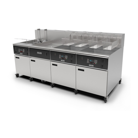
EOF SERIES
Operations & Service Manual
Electric Fryers
Model: EOF-20/FFLT/24
ISO 9001-2015 Registered • Committed to Quality
2750 Gunter Park Drive West • Montgomery, AL 36109 USA
Phone: 334.272.1457 • Toll Free: 800.554.4537
(USA & Canada Only)
Fax: 334.239.4117 • Website: www.gfse.com
Printed in USA, Form No. 60221 (Rel. Date: Nov.1999, Rev. Date: Oct.2017, Rev. G)
Advertisement
Table of Contents


Need help?
Do you have a question about the EOF Series and is the answer not in the manual?
Questions and answers