Table of Contents
Advertisement
Quick Links
Advertisement
Table of Contents

Related Manuals for Minebea Intec CSD-903


Summary of Contents for Minebea Intec CSD-903
- Page 1 Operating instructions Weight indicator CSD-903 Translation of original operating instructions 949905090300 Edition 1.0.0 08/09/2019 Minebea Intec GmbH, Meiendorfer Str. 205 A, 22145 Hamburg, Germany Phone: +49.40.67960.303 Fax: +49.40.67960.383...
- Page 2 Any information in this document is subject to change without notice and does not represent a commitment on the part of Minebea Intec unless legally prescribed. This product should be operated/installed only by trained and qualiied personnel. In correspondence concerning this product, the type, name, and release number/serial number as well as all license numbers relating to the product have to be cited.
-
Page 3: Table Of Contents
Weight indicator CSD-903 Table of contents Table of contents Introduction............................9 Read the manual................................. 9 This is what operating instructions look like ......................9 This is what lists look like............................9 This is what menu items and softkeys look like..................... 9 This is what the safety instructions look like...................... - Page 4 Weight indicator CSD-903 Table of contents Parameters to be set where necessary after calibration ..................35 Calibration procedures ............................37 6.3.1 Calibration low .............................. 37 6.3.2 Switch to calibration mode...........................38 6.3.3 Set the scale interval .............................38 6.3.4 Set the maximum load ..........................39 6.3.5...
- Page 5 Weight indicator CSD-903 Table of contents 8.12 Setting in set mode 2 or preset tare weight set....................60 8.12.1 Stability detection............................60 8.12.2 Unit display in the sub-display section ......................60 8.13 Gravity acceleration compensation........................60 8.13.1 Setting method for gravity acceleration compensation value ...............60 8.13.2...
- Page 6 Weight indicator CSD-903 Table of contents 10.9 Hold ................................... 80 10.9.1 HOLD operation ............................80 10.9.2 HOLD target..............................80 10.10 Sub-display section..............................81 10.10.1 Sub-display section value selection......................81 10.11 Accumulation ................................82 10.11.1 Accumulation function operating condition .....................82 10.11.2 Execute accumulation ...........................82 10.11.3...
- Page 7 Weight indicator CSD-903 Table of contents 11.7.2 Function of SQ function data ........................114 Various SQ function data functions ....................117 12.1 Weighing mode................................ 117 12.2 Control mode ................................117 12.3 Comparison signal operation ..........................117 12.4 Near zero (ZERO BAND) comparison operation ....................117 12.5 Full comparison operation .............................
- Page 8 Calibration mode for digital linearization ....................159 17.1.4 Calibration of Zero point only ........................163 Options ............................165 18.1 Analog output ................................. 165 18.1.1 Current output speciications (model: CSD-903-P07) ................165 18.1.2 Voltage output speciications (model: CSD-903-P25)................165 EN-6 Minebea Intec...
- Page 9 18.3 RS-232C and RS-422/485 interface ........................173 18.3.1 RS-232C interface speciication (P/N: CSD-903-P74)................173 18.3.2 RS-422/485 interface speciication (P/N: CSD-903-P76) ..............174 18.3.3 Operation mode of RS-232C and RS-422/485 ..................174 18.3.4 Output target synchronized with RS-232C print for RS-232C and RS-422/485....... 175 18.3.5...
- Page 10 Weight indicator CSD-903 Table of contents 21.2 Speciications ................................233 21.2.1 Analog speciications ..........................233 21.2.2 Display speciications..........................233 21.2.3 Interfaces...............................235 21.2.4 General speciications ..........................237 21.2.5 Standard shipping speciications ......................238 21.2.6 Accessories..............................238 21.3 Data format of command mode...........................239 21.3.1 Data format synchronizing with data format in stream mode .............239...
-
Page 11: Introduction
1 Introduction Weight indicator CSD-903 Introduction Read the manual Please read this manual carefully and completely before using the product. This manual is part of the product. Keep it in a safe and easily accessible location. This is what operating instructions look like 1. -
Page 12: Hotline
Weight indicator CSD-903 1 Introduction NOTICE Warning of damage to property and/or the environment. NOTICE indicates that damage to property and/or the environment may occur if appropriate safety measures are not observed. Take the corresponding safety precautions. Note: User tips, useful information, and notes. -
Page 13: Safety Instructions
2 Safety instructions Weight indicator CSD-903 Safety instructions General information Thanks you for purchasing the Weight Indicator CSD-903. This Operating instructions describes how to use the device and provides other useful information. Incorrect handling may cause the device to malfunction. -
Page 14: Installing The Instrument
Installing the instrument NOTICE Warning of damage to property and/or the environment. Install CSD-903 based on the following dimensions. Ensure suicient space around the instrument. The following are the dimensions of CSD-903 and the clearance required. Front Side 10.2 136.5... - Page 15 136.5 all dimensions in mm Applicable environment The CSD-903 may be used under humid or dusty conditions. In this case, insert the attached panel mount gasket attached between the control panel (cabinet) and the main body. The panel mount gasket ensures the front panel section of CSD-903 is dustproof and waterproof in compliance with IP65 (International Protection Code).
-
Page 16: Power Supply
Check that the power supply is OFF when installing cables. Before switching on the power, check that the supplied power is identical to the device voltage/speciications. Please contact a Minebea Intec sales or service oice if they do not match. -
Page 17: Conformed Standards
Do not forcibly press the panel sheet against the instrument. 2.3.5 Conformed standards CSD-903 complies with the following standards. EN61326: 2013 Electrical equipment for measurement, control and laborato- ry use - EMC requirements. Immunity test requirements for equipment intended for use in industrial locations. - Page 18 Weight indicator CSD-903 2 Safety instructions Note: The device running software Ver. 2.100 or later conforms with JIS standards. CAUTION Warning of personal injury and damage to property. Strictly observe the following conditions of use to ensure that the device complies with the below standards.
-
Page 19: Names And Functions Of Parts
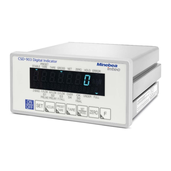
3 Names and functions of parts Weight indicator CSD-903 Names and functions of parts Front panel Condition display section 1 Displays the CSD-903 condition. STABLE Lights when the weighing operation is stable PRESET TARE Blinks while setting preset tare weight cancellation... - Page 20 Weight indicator CSD-903 3 Names and functions of parts Condition display section 2 Z-BAND Lights when a gross weight or net weight load value is less than the set near zero Blinks during [Z-BAND] setting and selection F. (Coarse) Lights when coarse low output signal is ON in sequential mode...
-
Page 21: Rear Panel
3 Names and functions of parts Weight indicator CSD-903 Switches displayed data between gross weight and net weight. Lowers the selected digit by 1. Saves the current load value as the zero point and sets the display to zero. Executes the function assigned to the F key. -
Page 22: Side
Up to 6 load cells (350 Ω) can be connected when the bridge power supply is 10 V Side Model instructions stamp Indicates the model number Panel metal mount Use to connect the CSD-903 and the control panel EN-20 Minebea Intec... -
Page 23: Wiring
Use shielded cable for connection with external control I/O, and connect the shield with the F.G terminal of the power supply terminals. Connection with load cells The CSD-903 needs to be connected to a load cell to facilitate weighing. Examples of CSD-903 connected with load cells are given below. Note:... -
Page 24: 6-Wire Connection Cable
4.2.1 6-wire connection cable Connect CSD-903 to a load cell using a 6-wire cable as follows. Note: The colors listed here apply for the Minebea Intec load cell and connection cables of type "PR …" Load cell + EXC Load cell power supply V+... -
Page 25: 4-Wire Connection Cable
4.2.2 4-wire connection cable Connect CSD-903 to a load cell using a 4-wire cable as follows. Note: The colors listed here apply for the Minebea Intec load cell and connection cables of type "PR …" Additional bridges Load cell + EXC... -
Page 26: Connecting Load Cells In Parallel
More than one load cell can be connected in parallel for use as a hopper scale or a truck scale. Cable junction box realizes easy parallel connection. Note: CSD-903 can make up to 6 parallel connections when the load cell is 350 Ω type. Please consult Minebea Intec as for a method over 5 parallel connections. Note: The colors listed here apply for the Minebea Intec load cell and connection cables of type "PR …"... -
Page 27: Connection With Power Supply And The Ground
4 Wiring Weight indicator CSD-903 Connection with power supply and the ground Connect and ground the power supply with the terminals on the rear panel shown as below igure. 100 V AC to 240 V AC (Permissible range: 85 V AC to 264 V AC) -
Page 28: Connecting The External Control I/O
Weight indicator CSD-903 4 Wiring 4.4 Connecting the external control I/O This function facilitates external control using the external control I/O connector on the rear panel. The external control input is executed by using a contact or open collector to bridge each input and COM 1 after wiring the connector. -
Page 29: Output Connection
4 Wiring Weight indicator CSD-903 4.4.2 Output connection Output 1 Output 2 Output 3 Output 4 Surge elimination device Output 5 B1 to B11 Output 6 Load Output 7 Output 8 Output 9 COM 2 Output 10 Open collector rating:... - Page 30 This internal circuit is insulated by a optocoupler. Connect the shield to the F.G. terminal on the terminal board of the RS-485 interface or 2-pin method serial interface when CSD-903 conforms to CE mark applicable standards or JIS standards. EN-28...
-
Page 31: Operating
5 Operating Weight indicator CSD-903 Operating Character display pattern The display pattern in seven segments indicator of this device is shown in the table below. Mode changeover The device has various modes, suited to diferent operating situations. Change the mode by key operation. - Page 32 Weight indicator CSD-903 5 Operating Power ON Display check (All light on) Weighing mode (Display weight value) Stand-by condition (Light off the weight value) Set mode 1 Display of Refer to the C function mode Display of Refer to the Calibration mode...
-
Page 33: Function Settings Table
5 Operating Weight indicator CSD-903 C function mode Sets C function data to activate various functions related to calibration. [CFUNC] Calibration mode Sets calibration data to display the signal from the load cell as an accurate load. [CAL] Check mode... - Page 34 Weight indicator CSD-903 5 Operating Function No. Initial Customer’s Function No. Initial Customer’s value setting value setting CF-14 CF-72 010000 CF-15 CF-90 CF-16 CF-91 10000 CF-17 CF-92 10000 CF-18 CF-93 00000 CF-20 CF-94 03000 CF-21 CF-97 CF-25 CF-98 – CF-26 CF-99 –...
- Page 35 5 Operating Weight indicator CSD-903 Function No. Initial Customer’s Function No. Initial Customer’s value setting value setting F-02 F-49 F-04 F-50 F-05 F-51 F-06 F-52 F-07 F-55 F-08 0000 F-60 F-09 0000 F-61 F-10 F-62 F-11 F-63 F-15 F-64 F-16...
- Page 36 Weight indicator CSD-903 5 Operating Function No. Initial Customer’s Function No. Initial Customer’s value setting value setting F-47 Sub-display panel setting table (F-19) Contents Contents value value K Brand (1 digit) / S1 (6 digits) / S3 (6 digits) A Brand (1 digit) / Accumulation...
-
Page 37: Calibration
6 Calibration Weight indicator CSD-903 Calibration The operation of matching the device display with the weight on the load cell is called calibration. It facilitates accurate display of the electrical signal from the load cell as a weight. For example, calibration adjusts the display of the instrument to 100.00 precisely when a weight of 100 kg is placed on the load cell. - Page 38 Weight indicator CSD-903 6 Calibration This function compensates for SPAN error by setting diferent gravity accelerations for the places of calibration and usage (refer to Chapter 8.13). Note: Calibrate as necessary when the usage environment changes. Performance is efective at display resolution of 10 000 or less.
-
Page 39: Calibration Procedures
6 Calibration Weight indicator CSD-903 Calibration procedures 6.3.1 Calibration low Step 1 Connect to the load cell Connect the load cell with the instrument. Step 2 Turn on the power supply. Power up the system. Step 3 Set the bridge power supply. -
Page 40: Switch To Calibration Mode
Weight indicator CSD-903 6 Calibration 6.3.2 Switch to calibration mode Stand-by condition Press the [ON-OFF] key to move from normal weighing mode to the stand-by condition. [CFUNC] 2. Press the [ON-OFF] key while pressing the [SET] key. [CFUNC] is displayed. -
Page 41: Set The Maximum Load
6 Calibration Weight indicator CSD-903 6.3.4 Set the maximum load [DISP] Saved maximum load When [F] key is pressed from the [DISP] display, [01000] is displayed. If the maximum load has already been changed, the currently saved maximum load is displayed. -
Page 42: Zero Point Calibration
Weight indicator CSD-903 6 Calibration Value of the load cell weight 2. Press the [F] key after setting [ZERO] ▼ Zero point calibration 6.3.6 Zero point calibration [ZERO] is displayed when SPAN calibration starts. Select the zero calibration method Method by weight data (status of initial load) ⇨ Press the [F] key and execute the "Method by measuring data". -
Page 43: Span Calibration
6 Calibration Weight indicator CSD-903 [Z MV] When the[PRESET TARE WEIGHT] key is pressed, [Z MV] is displayed. 2. When the[F] key is pressed, [✶.✶✶✶✶✶] is displayed. [✶.✶✶✶✶✶] is the saved load cell output voltage. mV/V Saved load cell output voltage. - Page 44 Weight indicator CSD-903 6 Calibration 6.3.7.1 Method by weight Place the weight corresponding to the mass on the load cell (Setting described in Chapter 6.3.5). [SPAN] Press the[F] key with the weight on the load cell. Under the SPAN calibration [SPAN] 2.
-
Page 45: Quit Calibration
6 Calibration Weight indicator CSD-903 Set the load cell output voltage: mV/V 3. Press the [F] key after setting [END] ▼ End. Error display in span calibration [SP-L]: The display blinks for about 2 seconds if ([Load cell output voltage at span point] –... - Page 46 Weight indicator CSD-903 6 Calibration 2. Press the[ON-OFF] key with the[SET] key. [CFUNC] is displayed. 3. Press the [NET-GROSS] key. [CAL] is displayed. [CAL] 4. Press the[F] key. [CCAL] is displayed. [CCAL] [CADJ] Zero ine calibration mode 5. Press the [NET-GROSS] key to display[CADJ]and move to zero ine calibration mode.
- Page 47 6 Calibration Weight indicator CSD-903 [SPAN] Precedes operation of "Span ine calibration" if executing span ine calibration. Otherwise, press the [NET-GROSS] key, and proceed to "Exit ine calibration mode" after [END]is displayed. ▼ Span ine calibration. 6.4.1.2 SPAN ine calibration...
-
Page 48: Digital Linearization
Weight indicator CSD-903 6 Calibration Digital linearization After calibration, a weighing error of several scale intervals may arise between ZERO and SPAN (maximum load) due to the inluence of the load cell. Digital linearization is a function that compensates up to three points, excluding ZERO and SPAN, to reduce weighing error. - Page 49 6 Calibration Weight indicator CSD-903 [P-1] Pressing the [F] key twice from the[LNR] display to display[P-1]. The display moves to [P-1] → [P-3] by pressing the [TARE WEIGHT] key. Select the numbers of the points for linearization compensation, and press the [F] key.
-
Page 50: Calibration Of Zero Point Only
Weight indicator CSD-903 6 Calibration Stand-by condition 6. Set to stand-by condition by pressing the [ON-OFF] key. The digital linearization is complete. Ensure that the value of weights to be compensated [LNR-1] < [LNR-2] < [LNR-3]. The linearization compensation cannot be executed above the maximum load (refer to Chapter 20.2.1). -
Page 51: Cal-Switch
6 Calibration Weight indicator CSD-903 Switch the display to [TZERO] by pressing the [F] key on the [TARE WEIGHT]display. Ensure that nothing is on the load cell other than the tare weight outside maximum load. [TZERO] 2. The display of [TZERO] blinks after pressing the [F] key and zero point calibration starts. - Page 52 Weight indicator CSD-903 6 Calibration The CAL switch (1) is located behind the cover (2) at the right of the RS-485 interface and 2-wire serial interface terminals on the rear panel. 2. Switch the CAL switch (1) ON. To release the lock, switch the CAL switch OFF.
-
Page 53: Function Mode
7 C function mode Weight indicator CSD-903 C function mode The various calibration functions become efective by setting the C function data. C function mode setting method Weighing mode Stand-by condition Set the condition from normal weighing mode to stand-by condition by pressing the [ON-OFF] key. -
Page 54: C Function Data Functions
Weight indicator CSD-903 7 C function mode C function data functions Item Function No. Setting value Contents Decimal point display position CF-01 No decimal point 1234.5 123.45 12.345 1.2345 A/D sampling rate CF-02 20 times/s 200 times/s Overload display condition... - Page 55 7 C function mode Weight indicator CSD-903 Item Function No. Setting value Contents Power on zero operation CF-15 Invalid Valid Tare weight cancellation opera- CF-16 Operation when stable and 0 < gross ting condition weight ≤ maximum load Unconditional operation and 0 < gross weight ≤...
- Page 56 Weight indicator CSD-903 7 C function mode Item Function No. Setting value Contents Setting the scale interval of the CF-41 1 scale interval second range 2 scale interval 5 scale interval 10 scale interval 20 scale interval 50 scale interval...
- Page 57 7 C function mode Weight indicator CSD-903 Item Function No. Setting value Contents Stability detection duration du- CF-97 00 ~ 99 Unit: 0.1 s ring calibration 00: Stability detection during calibration Digital linearization clear CF-98 The data compensated by digital lineariza- tion is cleared.
-
Page 58: Various Operations By C Function Data
The voltage (DC) excitation of the load cell can be selected from [DC10 V], [DC5 V] and [DC2.5 V]. The default is [DC10 V]. If a zener barrier is used, apply CSD-903 by selecting the excitation according to the below table. System coniguration... -
Page 59: Net Weight Sign Reversal Function
8 Various operations by C function data Weight indicator CSD-903 System coniguration Excitation 10 V 2.5 V 5 load cells + cable junction box + Zener barrier × × ◯ 6 load cells + cable junction box + Zener barrier ×... -
Page 60: Zero Tracking
Weight indicator CSD-903 8 Various operations by C function data ZERO tracking The zero tracking function compensates the gradual zero drift under constant conditions and stabilizes the zero point. 8.8.1 ZERO tracking target The ZERO tracking target is set by C function CF-12. -
Page 61: Power On Zero
8 Various operations by C function data Weight indicator CSD-903 Note: ZERO tracking does not operate when the setting for either C function CF-13 or CF-14 is 0. Do not use ZERO tracking when the load luctuates around zero. Note that ZERO tracking might become efective even if actual load change is rapid when the load change dampens due to the strength of the digital ilter and the stabilization ilter. -
Page 62: Clear At Power On
Weight indicator CSD-903 8 Various operations by C function data The default is [Operation when stable and 0 < gross weight ≤ maximum load]. Note: Tare weight cancellation is not accepted when the gross weight value exceeds the irst range. -
Page 63: District Number For Place Of Use (When Cf-25 = 0)
8 Various operations by C function data Weight indicator CSD-903 [Set the district number] or [Set the numerical value of gravity acceleration] can be selected. The default is [Set the district number]. 8.13.2 District number for place of use (when CF-25 = 0) The district number for the place of use is set by C function CF-26. -
Page 64: Automatic Range Switch
Weight indicator CSD-903 8 Various operations by C function data District Acceleration Corresponding districts (m/s 9.800 Fukushima Prefecture, Ibaraki Prefecture, Niigata Prefecture 9.799 Tochigi Prefecture, Toyama Prefecture, Ishikawa Prefecture 9.798 Gunma Prefecture, Saitama Prefecture, Chiba Prefecture, Tokyo (excluding the jurisdiction of the branch administrative oices Hachijojima and Ogasawara), Fukui Prefecture, Kyoto Prefecture, Tottori Prefecture, Shimane Prefecture 9.797... -
Page 65: Setting The Limit Value For The Second Range
8 Various operations by C function data Weight indicator CSD-903 8.14.3 Setting the limit value for the second range The limit value for the second range is set by C function CF-42. Setting range: 0 to 999999 The default is [003000]. -
Page 66: Stability Detection Duration During Calibration
Weight indicator CSD-903 8 Various operations by C function data Example 2 Net value cancelled 300 g tare weight set in Example 1 Scale interval 1 g Scale interval 0.5 g Scale interval 0.1 g Net Value –300 g 600 g... -
Page 67: Memory Clear
8 Various operations by C function data Weight indicator CSD-903 Stand-by condition [LNR.CLR] [CF-99] 3. [CF-99] is displayed if the [F] key is pressed while[LNR.CLR] blinks. Digital linearization is complete. 8.17 Memory clear Memory clear is executed by C function CF-99. The C function settings returned to the default. -
Page 68: Function Mode
Weight indicator CSD-903 9 Function mode Function mode Various functions are activated by setting the function data. Function mode setting method Weighing mode [FUNC.] Change from normal weighing mode to the [FUNC] display by the [SET] key. [F-01], [F-02] 2. Press the [F] key[ to display F-01]. -
Page 69: Details Of Function Data
9 Function mode Weight indicator CSD-903 Details of function data Item Function No. Setting Contents Digital ilter setting F-01 001 ~ 256 Unit: Moving average time 1 time) Analog ilter setting F-02 2 Hz 4 Hz 6 Hz 8 Hz... - Page 70 Weight indicator CSD-903 9 Function mode Item Function No. Setting Contents Automatic print operation F-16 00 to 11 digit: Manual print operation is efective only when stable 0: Efective only when stable 1: Always efective digit: Automatic print operation 0: Automatic printing of...
- Page 71 9 Function mode Weight indicator CSD-903 Item Function No. Setting Contents Q Brand (1 digit)/Over (5 digits)/Under (5 digits) R Brand (1 digit)/Accumulation times (6 digits) S Brand (1 digit)/Accumulation value (10 digits) Brand (1 digit)/Last accumulated data (6 digits)
- Page 72 Weight indicator CSD-903 9 Function mode Item Function No. Setting Contents Comparator hysteresis F-24 On delay operation condition Of delay Comparator hysteresis da- F-25 00 ~ 99 Unit: 1 D ta width 00: Hysteresis OFF Comparator hysteresis F-26 00 to 99 Unit: 0.1 s...
- Page 73 9 Function mode Weight indicator CSD-903 Item Function No. Setting Contents Synchronized with accumulation signal Synchronized with print signal RS-232C/422/485 output F-41 Display interlock target (RS-232C: Valid Gross weight at F-40 = 1 or Net weight 4; RS-422/485: Valid at F-49 =...
- Page 74 Weight indicator CSD-903 9 Function mode Item Function No. Setting Contents RS-422/485 operation F-49 Command mode mode Stream mode Accumulation function F-50 000 to 121 Accumulation command operation operating condition 000* digit: 0 = only when stable; 1 = Always...
- Page 75 9 Function mode Weight indicator CSD-903 Item Function No. Setting Contents [PRESET TARE WEIGHT] key operation [TARE WEIGHT] key operation [NET-GROSS WEIGHT] key operation [ZERO] key operation [F] key operation Zero clear Tare weight clear Inlow start Discharge start Inlow/Discharge changeover ON: Discharge;...
- Page 76 Weight indicator CSD-903 9 Function mode Item Function No. Setting Contents External control INPUT8 F-67 Optional, in addition to F-60 operation setting External control INPUT9 F-68 Optional, in addition to F-60 operation setting External control OUTPUT1 F-70 operation setting Stable...
- Page 77 9 Function mode Weight indicator CSD-903 Item Function No. Setting Contents External control OUTPUT7 F-76 Optional, in addition to F-70 operation setting External control OUTPUT8 F-77 Optional, in addition to F-70 operation setting External control OUTPUT9 F-78 Optional, in addition to F-70...
-
Page 78: Various Operations By Function Data
Weight indicator CSD-903 10 Various operations by function data 10 Various operations by function data 10.1 Digital ilter The digital ilter function stabilizes A/D converted data by moving average processing. The moving average rate is selected by function F-01. Setting range: 001 to 256 (Unit: Moving average frequency of 1 time) The default is [16 times]. -
Page 79: Key Lock Function
10 Various operations by function data Weight indicator CSD-903 The default is [05]. Example The data width over which the stabilization ilter is executed is selected by function F-06. The stabilization ilter data width for set value "n" is obtained as follows. -
Page 80: Key Lock 2
Weight indicator CSD-903 10 Various operations by function data 10.5.2 Key lock 2 Function F-09 sets whether key operation of [TARE WEIGHT/▲], [NET/GROSS WEIGHT/▼], [ZERO] or [F/↵] are[valid] or [invalid]. Setting range: 0000 to 1111; 0: Invalid; 1: Valid digit: TARE WEIGHT/▲... -
Page 81: Preset Tare Weight Cancellation Input
10 Various operations by function data Weight indicator CSD-903 10.7 Preset tare weight cancellation input The preset tare weight cancellation function executes tare weight cancellation according to the digital input setting. 10.7.1 Preset tare weight cancellation operating condition Preset tare weight cancellation can be from [Efective], [Invalid]and [Net weight ofset operation] by function F-15. -
Page 82: Net Weight Ofset Operation
Weight indicator CSD-903 10 Various operations by function data 10.7.3 Net weight ofset operation If preset tare weight cancellation is set as [Net weight ofset operation] and zero set is executed with the gross weight displayed, net weight ofset is not cleared. -
Page 83: Sub-Display Section
10 Various operations by function data Weight indicator CSD-903 Note: [OL] or [OVF] is displayed if [OL] or [OVF] error occurs during load display value holding operation. 10.9.2.2 Comparison result hold Valid and invalid for comparison result hold operation is selected by the 10 digit of F-18. -
Page 84: Accumulation
Weight indicator CSD-903 10 Various operations by function data 4: D Brand (1 digit)/Last accumulated data (6 digits)/OK (6 digits) 5: E Brand (1 digit)/Accumulation times (6 digits)/OK (6 digits) 6: F Brand (1 digit)/OK (6 digits)/Accumulation value (8 digits) -
Page 85: Display Range For Accumulated Value And Count
10 Various operations by function data Weight indicator CSD-903 10.11.2.2 Automatic accumulation When the value set for the 10 digit for F-50 is 0: Automatic accumulation does not function; 1: Accumulation automatically synchronizes with the inish signal; and, 2: Accumulation functions automatically provided the stability sign of status display is lit. -
Page 86: Brands (Products)
Brand comparison values can be set for individual brand numbers. Weighing is controlled using the various brand settings to ensure the target (OK) weight is achieved. The CSD-903 can save up to 8 brands. For details of brand settings, refer to Chapter 11. 10.12.1 Brand changeover The brand number can be changed by function, external control input or communication. -
Page 87: External Control I/O Settings
10 Various operations by function data Weight indicator CSD-903 6: Tare weight clear Executes tare weight cancellation Accumulation clear Clears the accumulation value and accumulation times 8: Weighing comparison Switches to check setting mode 9: Forced inlow inish Force-inishes weighing operation 10.14 External control I/O settings... -
Page 88: External Control Output Setting Method
Weight indicator CSD-903 10 Various operations by function data 22: Force-inishes weighing Inputs the signal to force-inish weighing operation operation 23: Force-inish low Inputs the signal to force-inish low 24: Accumulation clear Clears the accumulation value and the accumulation times of all brands... -
Page 89: Memory Clear
10 Various operations by function data Weight indicator CSD-903 14: D. (Fine) FLOW/S3 Lights when ine low output signal is [ON]in sequential mode Lights when S3 output signal is [ON]in check mo- de 1 or 2 15: OVER/S4 Lights when the judgment condition is over in sequential... -
Page 90: Weighing Mode
Weight indicator CSD-903 11 Weighing mode 11 Weighing mode CSD-903 has four weighing modes. Refer to Chapter 11.1 for details on settings. Set each weighing comparison value, refer to Chapter 11.2. Furthermore, there are two control modes, [Simple mode], [Sequential mode]. -
Page 91: Weighing Mode Setting Method
11 Weighing mode Weight indicator CSD-903 In this mode, each output is turned ON, according to the value set by the ON limit of the start signal (OFF → ON). If the set value is compared with the measurement value, and the comparison result is satisied, then the output goes OFF. -
Page 92: Setting Mode
Weight indicator CSD-903 11 Weighing mode [SQF-02] 5. Press the [F] key. The setting is registered. The following registered SQ function number is displayed. Select another SQ function number and repeat this procedure. [SQFUNC] 6. Press the [SET] key after registration is complete to switch to the [SQFUNC] display. - Page 93 11 Weighing mode Weight indicator CSD-903 [SET3] 5. Press the [F] key. The setting is registered. The following registered weighing comparison value is displayed. Select the next weighing comparison value and follow the same procedure to continue. 6. Press the [SET] key after registration is complete to switch to the [SQFUNC] display.
- Page 94 Weight indicator CSD-903 11 Weighing mode Brand number Set the brand number. The brand number can be changed by pressing the [ACCUM] key or the [PRESET TARE WEIGHT] key when is display- Setting range: 0 to 7; Unit: 1 D The default is [0].
-
Page 95: Weighing Comparison Value 2 Setting Mode
11 Weighing mode Weight indicator CSD-903 ZERO BAND Set the value of Near zero. Setting range: 00000 to 99999; Unit: 1 D The default is [00000]. When the weighing result is less than [FINAL (SET1) – OVER (SET5)], under output turns on. - Page 96 Weight indicator CSD-903 11 Weighing mode 5. Press the [F] key. The setting is registered. The following registered weighing comparison value is displayed. Select the next weighing comparison value and follow the same procedure to continue. 6. Press the [SET] key after registration is complete to switch to the [SQFUNC] display.
-
Page 97: Simple Mode
11 Weighing mode Weight indicator CSD-903 Near zero (ZERO BAND) Sets the value to output the near zero signal. Setting range: 000000 to 999999; Unit: 1 D The default is [000000]. When the weighing result is less than (ixed value – over), un- der output turns on. - Page 98 Weight indicator CSD-903 11 Weighing mode When the start signal is used, the inish signal is output. The comparative target of near zero and the comparative target of FULL value can be selected from Gross weight and Net weight. Under, Over and OK operate with net weight.
-
Page 99: Simple Discharge Mode
11 Weighing mode Weight indicator CSD-903 11.3.2 Simple discharge mode Simple discharge mode outputs a judgment condition that is satisied in comparison between the decrease in weighing amount for discharge of the weighed object and a set amount. Judgment condition... -
Page 100: Sequential Mode
Weight indicator CSD-903 11 Weighing mode Weighing Setpoint - Preset 2 Setpoint - Preset 1 Setpoint - Overshoot Setpoint Time Tare Start Coarse flow Middle flow Fine flow Coarse flow weighing delay timer Operates at the input of start signal... - Page 101 11 Weighing mode Weight indicator CSD-903 Status display Judgment condition OVER Net weight > [Final (SET1) + Over (SET5)] [Final (SET1) – Under (SET6) ≤ Net weight ≤ Final (SET1) + Over (SET5)] Operating explanations When the start signal is input, Coarse low, Middle low and Fine low turn on.
-
Page 102: Sequential Batch Mode (Batch Out)
Weight indicator CSD-903 11 Weighing mode Weighing Gross Final Setpoint – Overshoot Setpoint – Preset 1 Setpoint – Preset 2 Zero band Time Can be tare at the same time depends on settings. Batch start Waiting time until batch start... - Page 103 11 Weighing mode Weight indicator CSD-903 Status display Judgment condition [Final (SET1) – Under (SET6) ≤ Net weight ≤ Final (SET1) + Over (SET5)] Operating explanations Coarse low, Middle low and Fine low turn on when the start signal is input.
-
Page 104: Supplementary Batch (Discharge) Mode
Weight indicator CSD-903 11 Weighing mode Weighing Final Gross Zero band Setpoint – Preset 2 Setpoint – Preset 1 Setpoint – Overshoot Time Can be tare at the same time depend on the settings. Tare Batch start Batch start delay timer... - Page 105 11 Weighing mode Weight indicator CSD-903 Status display Judgment condition OVER Net weight > [Final (SET1) + Over (SET5)] [Final (SET1) – Under (SET6) ≤ Net weight ≤ Final (SET1) + Over (SET5)] Operating explanations When the start signal is input, Coarse low, Middle low and Fine low turn on.
-
Page 106: Automatic Overshoot Compensation
Weight indicator CSD-903 11 Weighing mode Weighing Setpoint Setpoint – Under setpoint Setpoint – Overshoot Setpoint – Preset 1 Setpoint – Preset 2 Time Batch start Batch start delay timer Batch monitoring timer Coarse flow Middle flow Fine flow Enforce within the [MAXTIME... -
Page 107: 4-Steps Check Mode 1
11 Weighing mode Weight indicator CSD-903 Note: Output for each comparison is synchronized with A/D sampling. 11.5 4-steps check mode 1 In 4-steps check mode 1, up to four comparison values and weighed values can be compared the results output. -
Page 108: Comparison Targets For S1, S2, S3 And S4 In Check Mode
Weight indicator CSD-903 11 Weighing mode Comparison Comparison target value (smaller) S1 setting value target value (larger) S1 Output ON S1 Output OFF 11.5.2 Comparison targets for S1, S2, S3 and S4 in check mode The comparison targets for the check mode can be set individually for S1, S2, S3 and S4 to [Display interlock], [NET WEIGHT] or [GROSS WEIGHT]. -
Page 109: Operation Of S0 In Control Mode
11 Weighing mode Weight indicator CSD-903 Net weight Net weight (smaller) (larger) S1 setting value S1 Output ON S1 Output OFF 11.5.3 Operation of S0 in control mode S0 can perform eight operations in this check mode. Select in function mode (F-23). - Page 110 Weight indicator CSD-903 11 Weighing mode comparison value comparison value (smaller) (larger) S1 set value S2 set value S2 output ON S2 output OFF S1 output ON S1 output OFF S0 output ON S0 output OFF When S1 is set to [Set value or less] and S2 to [Set value or more] with F-22 S1 output turns ON when S1 set value ≥...
-
Page 111: Hysteresis In Check Mode
11 Weighing mode Weight indicator CSD-903 comparison value comparison value (smaller) (larger) S1 set value S2 set value S2 output ON S2 output OFF S1 output ON S1 output OFF S0 output ON S0 output OFF 11.5.4 Hysteresis in check mode S1, S2, S3 and S4 can be set to prevent output relay chattering. -
Page 112: 4-Steps Check Mode 2
Weight indicator CSD-903 11 Weighing mode Hysteresis time width S1 set value Hysteresis data width Time → S1 output ON S1 output OFF When [Set value or more] is selected at S1 and hysteresis is set to[On delay] Hysteresis time width... -
Page 113: Comparison Targets For S1, S2, S3 And S4 In Check Mode
11 Weighing mode Weight indicator CSD-903 Setting brand comparison targets (Targeted functions from F21 to F26) Note: The ON/OFF status for each output may difer depending on selection. If an inappropriate mode is selected, the ON/OFF status may be incorrect, leading to malfunction of peripheral instruments. - Page 114 Weight indicator CSD-903 11 Weighing mode Note: Output ON/OFF status may difer with hysteresis setting. If an inappropriate mode is selected, the ON/OFF status may be incorrect, leading to malfunction of peripheral instruments. Operation at the judgment display section with hysteresis on in the case of S1 is shown below.
-
Page 115: Sq Function Mode
11 Weighing mode Weight indicator CSD-903 11.7 SQ function mode Sets SQ function data to activate various functions related to sequence operation. 11.7.1 SQ function mode setting method Weighing mode [FUNC.] Change from normal weighing mode to the [FUNC] display by the [SET] key. -
Page 116: Function Of Sq Function Data
Weight indicator CSD-903 11 Weighing mode 11.7.2 Function of SQ function data Item Function No. Setting Contents Weighing mode SQF-01 Simple mode Sequential mode 4-steps check mode 1 4-steps check mode 2 Control mode SQF-02 Batch mode Discharge mode External input changeover... - Page 117 11 Weighing mode Weight indicator CSD-903 Item Function No. Setting Contents M. (Middle) low comparison SQF-21 0000 to 9999 Unit: 0.01 s stop timer 0000* 0000: M. (Middle) low comparison stop ti- mer OFF D. (Fine) low comparison stop SQF-22 0000 to 9999 Unit: 0.01 s...
- Page 118 Weight indicator CSD-903 11 Weighing mode Item Function No. Setting Contents Calming time after post- SQF-38 0000 to 9999 Unit: 0.01 s batching 0000* 0000: Calming time after post-batching OFF Output time for the inlow inish SQF-40 0000 to 9999 Unit: 0.01 s...
-
Page 119: Various Sq Function Data Functions
12 Various SQ function data functions Weight indicator CSD-903 12 Various SQ function data functions 12.1 Weighing mode Weighing mode is selected by SQ function SQF-01. Weighing mode can be selected from the [Simple comparison mode] (Simple mode), [Sequential mode], [4-steps comparator mode 1] (4-steps check mode 1) and [4-steps comparator mode 2] (4-steps check mode 2). -
Page 120: Batch Start Time Operation Setting
Weight indicator CSD-903 12 Various SQ function data functions If [EXTERNAL] is selected, [SQERR 5] is displayed. Setting range: 0000 to 9999; Unit: 1 s; 0000: OFF The default is [0000] 12.7 Batch start time operation setting 12.7.1 Start above Near Zero at the time of batch start Operation when input inlow start signal with weighing value exceeds [ZERO BAND] is selected by SQ function SQF-15. -
Page 121: Flow/Discharge Brand Setting Target
12 Various SQ function data functions Weight indicator CSD-903 12.11 Flow/Discharge brand setting target The Flow/discharge brand setting target is set by SQ function SQF-24. SQF-26: SQF-37 Automatic overshoot compensation width; Post-batching time; SQF-38: The calming time after post-batching can be set for each brand number selected as the low/discharge brand setting target. -
Page 122: Post-Batching Operation Setting
Weight indicator CSD-903 12 Various SQ function data functions 12.15 Post-batching operation setting Sets for the operation of post-batching. 12.15.1 Maximum time of post-batching Set the maximum time for post-batching by S function SF-35. Setting range: 000 to 255; Unit: 1 time; 000: OFF The default is [000]. -
Page 123: Discharge Operation Setting After Weighing Inish
12 Various SQ function data functions Weight indicator CSD-903 When [OL or unstable] is selected, the FINISH signal turns OFF when the display switches to OL or –OL or when the stable signal output turns OFF. When the [Near zero] is selected, the FINISH signal turns OFF when the near zero signal is output. -
Page 124: Sq Function Clear
Weight indicator CSD-903 12 Various SQ function data functions Stand-by condition [ACCUCLR] [SQF-99] 4. When [ACCUCLR] is blinking, press the [F] key to turn of the display and switch to [SQF-99] display. Memory clear is complete. 12.19 SQ function clear SQ function clear is executed by SQ function F-99. -
Page 125: Storage Location Of Setting Data
13 Storage location of setting data Weight indicator CSD-903 13 Storage location of setting data In this unit, each data is recorded in RAM and EEPROM as follows: The data in EEPROM can be stored almost permanent due to nonvolatile. -
Page 126: Check Mode
Weight indicator CSD-903 14 Check mode 14 Check mode In the check mode, the following conirmations can be made. EzCTS mode External control input operation Output voltage of the load cell Analog output (Option) ROM version External control output operation... -
Page 127: Ezcts Mode
▼ Conirmation of ROM version USB to RS-485 converter Connecting cable USB cable CSD–903 EzCTS is a PC application. EzCTS can read and write function data more easily than CSD-903. It is useful for maintenance and data back-up. Minebea Intec EN-125... -
Page 128: Conirmation Of Rom Version
In EzCTS mode, do not connect with applications other than EzCTS by the standard RS-485 line. Commands not used by EzCTS are not returned from CSD-903 in EzCTS mode. Only EzCTS communication functions in this mode. 14.3 Conirmation of ROM version [ROM] [V1.000]... -
Page 129: Conirmation Of External Control Output
14 Check mode Weight indicator CSD-903 [IN] When the [F] key is pressed from the[IN] display, [IN] blinks. The external control input signal ON/OFF status can be conirmed in the status display section. The status display lights when each external control input connector input is turned Pin No. -
Page 130: Conirmation Of Load Cell Output Voltage
Weight indicator CSD-903 14 Check mode Condition Pin No. NET WEIGHT OUTPUT5 ZERO OUTPUT6 HOLD OUTPUT7 ERROR OUTPUT8 Z-BAND OUTPUT9 F. (Coarse) FLOW/S1 OUTPUT10 M. (Middle) FLOW/S2 OUTPUT11 D. (Fine) FLOW/S3 OUTPUT12 OVER/S4 OUTPUT13 [MONT] ▼ Conirmation of load cell output voltage 14.7 Conirmation of load cell output voltage... -
Page 131: Conirmation Of Bcd Output
14 Check mode Weight indicator CSD-903 Note: The displayed load cell output voltage is a reference value. The displayed accuracy is approximately 0.5%. 14.8 Conirmation of BCD output (When BCD output is applied) [BCD] Press the [F] key from the[BCD] display. [0000000] is displayed, and the 100 digit blinks. - Page 132 Weight indicator CSD-903 14 Check mode [ON-OFF]: Quit check mode [ROM] Stand-by condition Note: Conirmation of analog output is not executed if analog output is not installed. EN-130 Minebea Intec...
-
Page 133: 15 2-Pin Method Serial Interface (S-I/F)
15 2-pin method serial interface (S-I/F) Weight indicator CSD-903 15 2-pin method serial interface (S-I/F) 15.1 Interface speciication Speciication Contents Baud rate 600 bps Data length 8 bit Parity bit Odd number Stop bit 1 bit Start bit 1 bit... -
Page 134: Explanation Of Format Data
Weight indicator CSD-903 15 2-pin method serial interface (S-I/F) Note: Only during the measurement mode, the output of serial data is done. The output of the data of S-I/F stops when the maximum display is set to six digits. Set the maximum display within ive digits when you use S-I/F. -
Page 135: Standard Rs-485 Communication
The default is [Command mode], refer to Chapter for more information. Command mode Data is sent back from CSD-903 to the host according to the command/data sent toCSD-903 by the host (personal computer, sequencer, etc.). Stream mode When RS-485 is used, this mode continues to output the latest data of the output target selected by function F-47. -
Page 136: Speciications Of Communication By Rs-485
16.3.4 Delay time of RS-485 return data Return data from the CSD-903 side can be delayed when the transmitting terminal on the host side enters a state of low impedance. Delay time for return data from the RS-485 interface is set by function F-45. -
Page 137: Transmission Data Decimal Point Detection
16 Standard RS-485 Communication Weight indicator CSD-903 16.3.5 RS-485 transmission data decimal point detection Transmission data decimal point detection for RS-485 is selected by function F-46. The default is [No decimal point]. 16.3.6 RS-485 interface stream mode output target The output target is selected by the function F-48. -
Page 138: One To N
Weight indicator CSD-903 16 Standard RS-485 Communication 16.4.2 One to N RS-485 host CSD-9xx RS-485 + Address 00 RS-485 - S. G. S. G. CSD-9xx Address 01 S. G. CSD-9xx A termination resistance should Address 31 be wired on the unit located farthest away from the host. -
Page 139: Modbus Communication
Communication with an instrument supported by ModBus communication can be carried out without an application. - Modbus is a registered trademark of Modicon, Inc. - Data communication with CSD-903 does not require a communication protocol application because it operates with the mapped memory operation shown in the table below. - Page 140 Weight indicator CSD-903 17 ModBus communication Address Data name INFLOW START UNUSED DISCHARGE START UNUSED MANUAL OVERSHOOT COMPENSATION ACCUMULATION COMMAND CLEAR THE LAST ACCUMULATED DATA UNUSED UNUSED EMERGENCY STOP UNUSED FORCED INFLOW FINISH UNUSED FORCED DISCHARGE FINISH ERROR RESET CHANGE OF HOLD/HOLD RELEASE...
- Page 141 17 ModBus communication Weight indicator CSD-903 Address Data name UNUSED DISCHARGE FINISH 33 to 35 UNUSED DURING WEIGHING SEQUENCE UNUSED WEIGHING SEQUENCE ERROR ABNORMAL WEIGHT ZERO ERROR ERROR UNUSED DURING TARE WEIGHT PRESET TARE WEIGHT CENTER OF ZERO GROSS WEIGHT DISPLAY...
- Page 142 Weight indicator CSD-903 17 ModBus communication Address Data name UNIT 3 to 4 TARE WEIGHT 5 to 6 GROSS WEIGHT 7 to 8 NET WEIGHT 9 to 11 UNUSED SEQUENCE ERROR NUMBER ABNORMAL WEIGHT ZERO ERROR ERROR UNUSED 33 to 34 BRAND NO.
- Page 143 17 ModBus communication Weight indicator CSD-903 Address Data name 803 to 806 BRAND NO. 3 ACCUMULATION VALUE (10 digits) 807 to 1056 UNUSED 1057 to 1058 BRAND NO. 4 ACCUMULATION TIMES 1059 to 1062 BRAND NO. 4 ACCUMULATION VALUE (10 digits)
- Page 144 Weight indicator CSD-903 17 ModBus communication Status Status is written as bits to input register addresses 51, 55, 59 and 63. Details Bit 15 STABLE Bit 14 TARE WEIGHT CANCELLATION SETTING Bit 13 TARE WEIGHT CANCELLATION Bit 12 GROSS WEIGHT...
- Page 145 17 ModBus communication Weight indicator CSD-903 Number Details If the load cell output and numerical input is equal to or less than –2.5 mV/V and exceeds the zero calibration range on the negative side during calibration If the load cell output and numerical input is equal to or more than 2.5 mV/V and exceeds the zero calibration range on the positive side...
- Page 146 Weight indicator CSD-903 17 ModBus communication Address Data name 285 to 286 BRAND NO. 1 POST-BATCHING TIME 287 to 288 BRAND NO. 1 CALMING TIME AFTER POST-BATCHING 289 to 290 BRAND NO. 1 AUTOMATIC OVERSHOOT COMPENSATION 291 to 522 UNUSED 523 to 524 BRAND NO.
- Page 147 17 ModBus communication Weight indicator CSD-903 Address Data name 1045 to 1046 BRAND NO. 4 UNDER 1047 to 1048 BRAND NO. 4 NEAR ZERO 1049 to 1050 BRAND NO. 4 FULL 1051 to 1052 UNUSED 1053 to 1054 BRAND NO. 4 CALMING TIME AFTER POST-BATCHING 1055 to 1056 BRAND NO.
- Page 148 Weight indicator CSD-903 17 ModBus communication Address Data name 1805 to 1806 BRAND NO. 7 OVERSHOOT/S4 1807 to 1808 BRAND NO. 7 PRIOR TO FIXED VALUE 1/S3 1809 to 1810 BRAND NO. 7 PRIOR TO FIXED VALUE 2/S2 1811 to 1812 BRAND NO.
- Page 149 17 ModBus communication Weight indicator CSD-903 Address Data name 57351 to 57352 F-04 DISPLAY TIMES 57353 to 57354 F-05 STABILIZATION FILTER SETTING 57355 to 57356 F-06 STABILIZATION FILTER DATA WIDTH 57357 to 57358 F-07 STABILIZATION FILTER TIME WIDTH 57359 to 57360...
- Page 150 Weight indicator CSD-903 17 ModBus communication Address Data name 57429 to 57430 F-43 RS-422/485 ADDRESS SETTING (Reference) 57431 to 57432 F-44 RS-422/485 CHANGEOVER (Reference) 57433 to 57434 F-45 RS-485 REPLY DATA DELAY TIME (Reference) 57435 to 57436 F-46 RS-232C/422/485 TRANSMISSION DATA DECIMAL...
- Page 151 17 ModBus communication Weight indicator CSD-903 Address Data name 57505 to 57506 F-81 EXTERNAL CONTROL OUTPUT 12 OPERATION SETTING 57507 to 57508 F-82 EXTERNAL CONTROL OUTPUT 13 OPERATION SETTING 57509 to 57510 UNUSED 57511 to 57712 F-84 CC-LINK OCCUPIED STATIONS...
- Page 152 Weight indicator CSD-903 17 ModBus communication Address Data name 57905 to 57906 CF-25 GRAVITATIONAL ACCELERATION COMPENSATION VALUE SETTING METHOD 57907 to 57908 CF-26 AREA CODE OF USAGE LOCATION 57909 to 57910 CF-27 AREA CODE OF CALIBRATION LOCATION 57911 to 57912...
- Page 153 17 ModBus communication Weight indicator CSD-903 Address Data name 58387 to 58388 SQF-10 WEIGHING TIME MONITORING TIMER 58389 to 58396 UNUSED 58397 to 58398 SQF-15 EFFECTIVE OVER NEAR ZERO AT FLOW START 58399 to 58400 SQF-16 AUTOMATIC TARE WEIGHT AT FLOW START...
-
Page 154: Calibration By Transmission Through Modbus Interface
Weight indicator CSD-903 17 ModBus communication Address Data name 58465 to 58466 SQF-49 TARE WEIGHT CLEAR ON DISCHARGE FINISH 17.1 Calibration by transmission through ModBus interface Proceed the setting according to the following fow chart in this calibration. 17.1.1 Calibration mode Each item of the low chart corresponds to each procedure described in Chapter 6.3.1. - Page 155 17 ModBus communication Weight indicator CSD-903 Note: While executing the calibration by transmission, (-RS) is displayed. When the calibration is compulsorily inished, all the data returns to the condition before the calibration without executing the registration. Please register the data for the calibration with the weight after conirming the stable condition without fail.
- Page 156 Weight indicator CSD-903 17 ModBus communication 17.1.1.6 Zero calibration by weighing value The load cell output value is registered in holding register address 56846 as the zero point. [1] is written in holding register address 56846. [1] is automatically rewritten as [0] after writing is completed.
- Page 157 17 ModBus communication Weight indicator CSD-903 Condition Error code Contents TE-H – 250 000 < Zero point mV/V value Error outside the setting range When data outside the setting range is entered, the following codes are set. Condition Error code...
-
Page 158: Zero And Span Ine Calibration Mode
Weight indicator CSD-903 17 ModBus communication 17.1.1.10 SPAN calibration by numerical input SPAN is registered by setting unit mV/V amount in holding register address 56843 to 56844. Setting range: 1 to 310 000 (0.0001 mV/V to 3.1 mV/V) SP-L error [22] (SP-L) is written in input register address 52 when the input load cell output value is 0 mV/V or less, which is less than the range of zero calibration on the negative side. - Page 159 17 ModBus communication Weight indicator CSD-903 ① Change to Zero point and SPAN point ine calibration mode ② Zero stability check ③ SPAN point ine calibration ④ SPAN stability check ⑤ SPAN point ine calibration ⑥ Finish Zero point and SPAN point ine calibration...
- Page 160 Weight indicator CSD-903 17 ModBus communication Coarse calibration on the negative side –10 TE-L error [20] (TE-L) is written in input register address 52 when the read load cell output value is less than –2.5 mV/V, which is outside the range of zero calibration on the negative side.
-
Page 161: Calibration Mode For Digital Linearization
17 ModBus communication Weight indicator CSD-903 SP-L error [22] (SP-L) is written in input register address 52 when the input load cell output value is 0 mV/V or less, which is less than the range of zero calibration on the negative side. - Page 162 Weight indicator CSD-903 17 ModBus communication ① Change to digital linearization mode ② Compensation at point ② Compensation at point 1 ② Compensation at point 2 ⑤ Compensation at point 2 ⑥ Stability check at point 3 ⑤ Compensation at point 3 ⑤...
- Page 163 17 ModBus communication Weight indicator CSD-903 Condition Error code Contents LN-L – Value at Point 1 < Zero point LN-H error [25] (LN-H) is written in input register address 52 when input load value is higher than the maximum load.
- Page 164 Weight indicator CSD-903 17 ModBus communication 17.1.3.6 Stability check at point 3 Place weights not exceeding the maximum load on the load cell. Stable/Unstable is read from holding register address 56845. 0: Unstable 1: Stable 17.1.3.7 Compensation at point 3 After putting the weight for the point to be compensated on the load cell, the weight at point No.3 is set and registered in holding register address 56855 to 56856.
-
Page 165: Calibration Of Zero Point Only
17 ModBus communication Weight indicator CSD-903 17.1.4 Calibration of Zero point only Each item of the low chart corresponds to each procedure described in Chapter 6.6. ① Changing to Zero point only calibration mode ② Zero stability check ③ Zero calibration using weight ④... - Page 166 Weight indicator CSD-903 17 ModBus communication Condition Error code Contents TE-H – 2.5 mV/V < Zero point Error outside the setting range When data outside the setting range is entered, the following codes are set. Condition Error code Contents Illegal data When data outside [1] is written.
-
Page 167: Options
18 Options Weight indicator CSD-903 18 Options 18.1 Analog output 18.1.1 Current output speciications (model: CSD-903-P07) Speciication Content Output 4 mA DC to 20 mA DC Load characteristic 510 Ω or less Non linearity Within 0.02 % F. S. Resolution... -
Page 168: Connection Of Analog Output
Weight indicator CSD-903 18 Options 18.1.3 Connection of analog output Current output ZERO SPAN F.G. A-OUT Screen Load resistance 510 Ω or less Voltage output ZERO SPAN F.G. A-OUT Screen Load resistance 5 kΩ or less Note: Use shielded cable and connect the shield to the F.G. terminal. - Page 169 18 Options Weight indicator CSD-903 Analog output Approx. 21.6 mA Approx. 11 V 20 mA Maximum display 10 V -20D display 4 mA Minimum display 0 Display Display Maximum display +9D of the maximum display Approx.2.4 mA Approx. -1 V CF-71 sets the display when the minimum value is output.
-
Page 170: Analog Output Ine Calibration
Weight indicator CSD-903 18 Options CF-71 sets the display when the minimum value is output. CF-72 sets the display when the maximum value is output. Example: CF-71: Set to 1 000 CF-72: Set to 5 000 The maximum value is output when the display is 5 000. -
Page 171: Bcd Output
18 Options Weight indicator CSD-903 18.2 BCD output 18.2.1 Speciications (model CSD-903-P15) The BCD output speciications are given below. Speciications Content BCD data Output 8 digit parallel output POL. (Polarity) Output ON for negative polarity output, OFF for positive po- larity output P.C. -
Page 172: Logic Of Bcd Output
Weight indicator CSD-903 18 Options 18.2.4 Logic of BCD output The logic of BCD output is selected by the setting of function F-32. Function no. Set value Contents F-32 0000 to 1111 0 0 0 0 Digital output logic (Load data, Decimal point data) POL. - Page 173 18 Options Weight indicator CSD-903 Pin No. Input/Output BCD code Pin No. Input/Output BCD code Output Output Output Output Output Output Decimal point Output Output Decimal point Output Output Decimal point Output Output Decimal point Output Output Stable Output –...
-
Page 174: I/O Equivalent Circuits
Weight indicator CSD-903 18 Options 18.2.8 I/O equivalent circuits Output section Input section +12V 2.2K OUTPUT INPUT COM. 3 COM. 3 = 30 V DC = 20 mA DC 18.2.9 Timing chart The following chart shows the BCD output timing. -
Page 175: Output Condition
Output logic set- Output data Transistor state Pin-to-COM level when an ting external voltage is applied Negative logic Positive logic 18.3 RS-232C and RS-422/485 interface 18.3.1 RS-232C interface speciication (P/N: CSD-903-P74) Item Speciication Communication method Half duplex Minebea Intec EN-173... -
Page 176: Rs-422/485 Interface Speciication (P/N: Csd-903-P76)
Communication data ASCII code Cable length ≤15 m Input/output monitor LED (TXD and RXD) 18.3.2 RS-422/485 interface speciication (P/N: CSD-903-P76) Item Speciication Communication method Half duplex Synchronizing method Start-stop Baud rate Selection: 1 200, 2 400, 4 800, 9 600, 19 200 and 38 400 bps... -
Page 177: Output Target Synchronized With Rs-232C Print For Rs-232C And Rs-422/485
Data is output at constant intervals in stream mode. Host-side control is disabled. Command mode Data is sent back from CSD-903 to the host according to the command/data sent to CSD-903 by the host (personal computer, sequencer, etc.). Execute communication according to the following procedure. -
Page 178: Communication Speciications By Rs-232C And Rs-422/485
Weight indicator CSD-903 18 Options Note: If an RS-232C interface is installed, function F-41 is valid if F-40 is set to [1 to 4]. If an RS422/485 interface is installed, function F-41 is valid if F-49 is set to [1]. -
Page 179: Pin Assignment Of The Rs-232C Interface
18 Options Weight indicator CSD-903 18.3.10 Pin assignment of the RS-232C interface Pin assignment of the RS-232C interface is given below. Pin number Signal name N. C. S. G. N. C. N. C. Plug: DE-9S-NR (JAE) or equivalent (not included) -
Page 180: Pin Assignment Of The 422/485 Interface
Weight indicator CSD-903 18 Options Wiring example 1: CSD-903 Host (25 pins) F. G. N. C. S. G. N. C. S. G. N. C. Wiring example 2: CSD-903 Host (9 pins) N. C. S. G. S. G. N. C. N. C. - Page 181 To suit the instrument with the CE conformity or applied JIS standard, please use a shielded cable and connect the shield to the serial interface output terminal board. 18.3.11.1 Connecting with CSD-903 The procedure to connect the CSD-903 with the RS-422/485 interface is given below. RS-422 host CSD-903 Address 00 TRM.
- Page 182 Weight indicator CSD-903 18 Options CSD-903 CSD-903 RS-422 Host RS-485 Host Address 00 Address 00 TRM. TRM. S. G. S. G. S. G. S. G. CSD-903 CSD-903 Address 01 Address 01 TRM. TRM. S. G. S. G. CSD-903 CSD-903 Address 09 Address 31 TRM.
-
Page 183: Data Format Of Command Mode
18 Options Weight indicator CSD-903 18.3.12 Data format of command mode Note: The address is ixed at [00] for the RS-232C interface. Load data enters from the right. [–] is entered for negative values and [+] for positive values. Zero suppression is performed on the load data. - Page 184 Weight indicator CSD-903 18 Options – Terminator Address 00 ~ 31 Terminator Address 00 ~ 31 Terminator Address 00 ~ 31 – Terminator Address 00 ~ 31 Command number 26 Terminator Address Command No. 00 ~ 31 Return (device → host)
- Page 185 18 Options Weight indicator CSD-903 Function Function Sign Load data (8 digits) Unit Kilo Newton Command number 27 Terminator Address Command No. 00 ~ 31 Return (device → host) Terminator Setting Address value 00 ~ 31 Sign Command No. 18.3.12.2 Reading weighing setting data (host →...
- Page 186 Weight indicator CSD-903 18 Options 18.3.12.3 Reading comparison data (host → device) Command No. Operation Reading S1 setting Reading S4 setting Reading S3 setting Reading S2 setting Reading full Reading near zero Reading tare weight Reading efective brand number Reading setting brand number...
- Page 187 18 Options Weight indicator CSD-903 a: Accumulate [1] = ON; [0] = OFF b: Preset tare weight [1] = ON; [0] = OFF c: Tare weight [1] = ON; [0] = OFF d: Gross weight [1] = ON; [0] = OFF e: Net weight [1] = ON;...
- Page 188 Weight indicator CSD-903 18 Options Terminator Address Command No. 00 ~ 31 Return (device → host) Terminator Address 00 ~ 31 Condition Command No. a: N.C. b: DISCHARGE (GATE OPEN) [1] = ON; [0] = OFF c: INFLOW FINISH [1] = ON; [0] = OFF d: N.C.
- Page 189 18 Options Weight indicator CSD-903 Under abnormal operation Return (device → host) Terminator Address 00 ~ 31 18.3.12.8 Change of condition (host → device) Command No. Operation GROSS WEIGHT DISPLAY NET WEIGHT DISPLAY ZERO Zero clear Tare weight Tare weight clear...
- Page 190 Weight indicator CSD-903 18 Options Under abnormal operation Return (device → host) Terminator Address 00 ~ 31 Note: Error is transmitted under the following conditions: Cannot execute ZERO set outside the efective range for Command 52 zero set Cannot apply tare weight cancellation with display ±OL for [Command 54]tare...
- Page 191 18 Options Weight indicator CSD-903 Under normal operation Return (device → host) Terminator Address Set value 00 ~ 31 Sign Command No. Under abnormal operation Return (device → host) Terminator Address 00 ~ 31 Note: Values are entered from the right.
- Page 192 Weight indicator CSD-903 18 Options Command No. Operation Writing S5 setting Writing S2 setting Writing full Writing near zero Writing tare weight Writing efective brand number Writing setting brand number Terminator Address Set value 00 ~ 31 Sign Command No.
- Page 193 18 Options Weight indicator CSD-903 Note: Values are entered from the right. Do not add a decimal point. Set the storage destination to Internal RAM when the set value is continuously changed and the number of EEPROM rewrites might exceed 1,000,000.
- Page 194 Weight indicator CSD-903 18 Options 18.3.12.12 Writing set values (host → device) Terminator Address Spaces 00 ~ 31 Number Command No. Under normal operation Return (device → host) Terminator Address Set value 00 ~ 31 Sign Number Command No. Under abnormal operation Return (device →...
- Page 195 18 Options Weight indicator CSD-903 Item Function No. Number Return command set value Lock key 1 0000 to 1111 (0 : Invalid; 1: Valid) : ON/OFF key : Setting key : Accumulation key : Tare weight set key Lock key 2 0000 to 1111 (0 : Invalid;...
- Page 196 Weight indicator CSD-903 18 Options Item Function No. Number Return command set value Sub-display section 0: OFF 1: A Brand (1 digit)/Accumulation times (6 digits)/Accumulation value (8 digits) 2: B Brand (1 digit)/Accumulation times (6 digits)/Last accumulation data (6 digits)
- Page 197 18 Options Weight indicator CSD-903 Item Function No. Number Return command set value 4-step check S0 operation con- 0: Always OFF dition 1: On when both S1 and S2 outputs are OFF 2: On when both S1 and S3 outputs are OFF...
- Page 198 Weight indicator CSD-903 18 Options Item Function No. Number Return command set value RS-2332C/422/485 communi- 00000 to 15121 cation speciication : Data bit length 0: 7bit; 1: 8 bit : Parity 0: No parity; 1: Even parity; 2: Odd parity : Stop bit 0: 1bit;...
- Page 199 18 Options Weight indicator CSD-903 Item Function No. Number Return command set value External control input 0: OFF INPUT1 operation setting 1: [ON-OFF] key operation 2: [SET] key operation 3: [ACCUM] key operation 4: [PRESET TARE WEIGHT] key operation 5: [TARE WEIGHT] key operation...
- Page 200 Weight indicator CSD-903 18 Options Item Function No. Number Return command set value External control OUTPUT1 ope- 00: OFF; 01: Stable; ration setting 02: During tare weight cancellation; 03: Gross weight display; 04: Net weight display; 05: Center zero; 06: During hold;...
- Page 201 18 Options Weight indicator CSD-903 Item Function No. Number Return command set value Overload display condition 0: Greater than ?maximum load + 9 D? 1: When the amount exceeds maximum load ±110% 2: Less than –20 D and larger than maximum...
- Page 202 Weight indicator CSD-903 18 Options Item Function No. Number Return command set value Range switch operation 0: Range change OFF; 1: Can be changed between two ranges; 2: Can be changed between three ranges Setting the scale interval of the 0: 1 scale interval;...
- Page 203 18 Options Weight indicator CSD-903 Item Function No. Number Return command set value Near zero comparison operation 72 0: Gross weight; 1: Net weight; 2: OFF; 3: |Gross weight|; 4 : |Net weight| Full comparison operation 0: Gross weight; 1: Net weight; 2: OFF; 3: |Gross weight|;...
- Page 204 Weight indicator CSD-903 18 Options Item Function No. Number Return command set value Discharge monitor timer 0000 to 9999 (Unit: 0.01 s) Discharge gate close delay time 72 0000 to 9999 (Unit: 0.01 s) Discharge inish output time 0000 to 9999 (Unit: 0.01 s) Tare weight cancellation at 0: Invalid;...
-
Page 205: Data Format Synchronizing With Data Format In Stream Mode
18 Options Weight indicator CSD-903 Error Details Remarks Command No. Error display for span calibration The load cell output voltage is 3.1 mV/V or more. Note: The error command is not returned if the address and completion code (terminator) cannot be detected. - Page 206 Weight indicator CSD-903 18 Options 18.3.13.1 When the setting of function F-41 (RS-232C/422/485) or function F-48 (standard RS-485) is set to (LOAD DISPLAY), (GROSS), or (NET) Return (device → Host) Terminator Load data Command No. Load data sign – Terminator...
-
Page 207: Data Format Communication Calibration
18 Options Weight indicator CSD-903 18.3.14 Data format communication calibration Note: The address becomes [00] ixation for the RS-232C interface. The load data enters from the right. The sign of [–] for minus and [+] for plus is entered. The load data performs zero suppress. - Page 208 Weight indicator CSD-903 18 Options ① Switch to communication calibration mode (refer to Chapter 6.3.2) ② Set the scale interval (refer to Chapter 6.3.3) ③ (3) Set weighing operation (refer to Chapter 6.3.4) ④ Set the mass for the weight (refer to Chapter 6.3.5)
- Page 209 18 Options Weight indicator CSD-903 18.3.14.1.1 to communication calibration mode (host → device) Terminator Address Spaces 00 ~ 31 Number Command No. Under normal operation Return (device → host) Terminator Address Spaces 00 ~ 31 Number Command No. Under abnormal operation Return (device →...
- Page 210 Weight indicator CSD-903 18 Options Under abnormal operation Return (device → host) Terminator Address 00 ~ 31 18.3.14.1.3 Setting the maximum load (host → device) Terminator Address Set value 00 ~ 31 Number Command No. Under normal operation Return (device → host)
- Page 211 18 Options Weight indicator CSD-903 Under abnormal operation Return (device → host) Terminator Address 00 ~ 31 18.3.14.1.5 Zero point stability check (host → device) Terminator Address 00 ~ 31 Number Command No. Under normal conditions Return (device → host)
- Page 212 Weight indicator CSD-903 18 Options Under abnormal operation Return (device → host) Terminator Address 00 ~ 31 Terminator Address 00 ~ 31 18.3.14.1.7 Numeric input of the load cell output voltage zero point registration (host → device) 18.3.14.1.7.1 Setting for the forth decimal point digit...
- Page 213 18 Options Weight indicator CSD-903 Under normal operation Return (device → host) Terminator Address Set value 00 ~ 31 Sign Number Command No. Note: Setting the ifth decimal point digit Example: Input data =100001 → 1.00001 mV/V Under abnormal operation Return (device →...
- Page 214 Weight indicator CSD-903 18 Options 18.3.14.1.8 SPAN point stability check (host → device) Terminator Address 00 ~ 31 Number Command No. Under stable conditions Return (device → host) Terminator Address 00 ~ 31 Number Command No. Under unstable conditions Return (device → host)
- Page 215 18 Options Weight indicator CSD-903 Terminator Address 00 ~ 31 18.3.14.1.10Numeric input of the load cell output voltage SPAN point registration (host → device) 18.3.14.1.10.1 Setting for the forth decimal point digit Terminator Address Set value 00 ~ 31 Sign Number Command No.
- Page 216 Weight indicator CSD-903 18 Options Under normal operation Return (device → host) Terminator Address Setting value 00 ~ 31 Sign Number Command No. Note: Setting the ifth decimal point digit Example: Input data =100001 → 1.00001 mV/V Under abnormal operation Return (device →...
- Page 217 18 Options Weight indicator CSD-903 18.3.14.1.11Calibration registration (host → device) Terminator Address 00 ~ 31 Number Command No. Under normal operation Return (device → host) Terminator Address 00 ~ 31 Number Command No. Under abnormal operation Return (device → host)
-
Page 218: Maintenance
Approx. 10 years (Environmental tempera- ture : 20°C ) Display module When using CSD-903 at the ambient temperature of approx. 50 °C, the display will licker is about 45 000 hours, and the phenomenon of the luminance’s decreasing. EEPROM When writing is made to EEPROM more than the time of lifetime, you can’t write to the data any more, so exchange shall be required. - Page 219 19 Maintenance Weight indicator CSD-903 Installation screws for rear panel Time lag fuse (2,5 A) 2. Remove the 6 screws (1) on the rear panel 3. Remove the contents in the case direction holding the rear panel 4. Replace the fuse (2) installed on the circuit board 5.
-
Page 220: Troubleshooting
When abnormal point(s) is/are found during the operation of the instrument, check by the following procedures. Moreover, when you cannot ind applicable item or solve the symptom of trouble even after you have taken some measures, contact with Minebea Intec. 20.1 Execute trouble shooting Execute troubleshooting. - Page 221 20 Troubleshooting Weight indicator CSD-903 Check of display ↓ Display the load. → No → Fuse is broken. → Yes → Replace fuse. ↓ ↓ ↓ [OL] display? → Yes → ① ↓ ↓ [-OL] display? → Yes → ①...
- Page 222 Weight indicator CSD-903 20 Troubleshooting ① ↓ 1. Remove the connection cable for the load cell from the terminal block for load cells. 2. Measure the voltage between A-C after short-circuiting A-F and C-G of terminal block. Set the load cell tester to DC voltage measurement.
- Page 223 Set the load cell tester to DC voltage measurement. ↓ The voltage between A and C is → No → Inform Minebea Intec about the stable in the set value of excitation contens of failure and situation at voltage. site in details.
- Page 224 ↓ ↓ Is the intended operation ma- → No → Set the operation of weighing, refer from Chapter 11.3 to 11.7.2. ↓ ↓ Inform Minebea Intec about the contens of failure and situation at site in details. EN-222 Minebea Intec...
- Page 225 → Yes → To serial interface communication face is wrong. check. ↓ ↓ Standard RS-485 and Modbus are → Yes→ Inform Minebea Intec about the wrong. contens of failure and situation at ↓ site in details. ↓ Correct connecting? → No →...
- Page 226 The target of print signal operation → No → Use the correct command/data, re- is correctly set. fer to Chapter 15.4. ↓ ↓ Inform Minebea Intec about the contens of failure and situation at site in details. EN-224 Minebea Intec...
- Page 227 Set the external control I/O. set? ↓ ↓ External control input is → Yes → Inform Minebea Intec about the contens of wrong. failure and situation at site in details. ↓ ↓ 50 ms or more of input sig- → No →...
- Page 228 ↓ ↓ RS-485 is wrong. → Yes → To the RS-485 check. ↓ ↓ Inform Minebea Intec about the contens of failure and situation at site in details. Analog output check ↓ Correct connecting? → No → Connect wires surely, refer to ↓...
- Page 229 ↓ ↓ The BCD output does not change. → Yes → Make the HOLD input opened. ↓ ↓ Inform Minebea Intec about the contens of failure and situation at site in details. RS-232C check ↓ Correct connecting? → No →...
- Page 230 Set the low control from [YES] to ↓ [NONE]. ↓ The change of RS-422/485 is pro- → No → Make the change of RS-422/485 perly set. correctly. ↓ ↓ Inform Minebea Intec about the contens of failure and situation at site in details. EN-228 Minebea Intec...
- Page 231 Enlarge the respon- ↓ se delay time of the instrument. ↓ Inform Minebea Intec about the contens of failure and situation at site in details. Minebea Intec EN-229...
-
Page 232: Error Display And Buzzer Sound
Blinks for about 2 seconds during calibration if [Maximum load (DISP)] < [Mass weight value (LOAD)]. A/D conversion error. Contact Minebea Intec. EEPROM writing error. Contact Minebea Intec. EEPROM reading error. Contact Minebea Intec. Blinks for about 2 seconds during calibration if load cell output and numeric input are –2.5 mV/V or less and outwith the zero ca-... -
Page 233: Error Sub-Display
Weight indicator CSD-903 The A/D load cell input is negative overload. All lights Blinks if accumulation value or accumulation times exceed the display range. Battery LO error. Contact Minebea Intec. Backup data corrupted. Contact Minebea Intec. 20.2.2 Error sub-display Error code... - Page 234 Weight indicator CSD-903 20 Troubleshooting Error code Error Contents Actions The gross weight is less Add the BRAND than the inal weighing value in discharge mode. Net weight > Final value – Empty the container overshoot Weighing begins with Check whether there is a "Start above near zero"...
-
Page 235: Appendix
21.1 Customer service Warranty The device warranty period is one year from the date of delivery. Consult Minebea Intec sales oice or point of purchase for repairs or customer service during the warranty period. Repair Before requesting a repair, check once again that all of the wiring/settings/adjustments are correct. - Page 236 Weight indicator CSD-903 21 Appendix Display increment 1 (can be changed to 2, 5, 10, 20 or 50) Display unit 7-segment green colored luorescent display tube with character’s height 11.55 mm, 7 digits Overload display [–OL] display for negative overload, [OL] display for...
-
Page 237: Interfaces
21 Appendix Weight indicator CSD-903 21.2.3 Interfaces External control input Any 9 functions can be selected from the following: OFF, [ON/OFF] key operation, [SET] key operation, [ACCUM.] key operation, [PRESET TARE WEIGHT/] key operation, [TARE WEIGHT/▲] key operation, [NET/GROSS WEIGHT/▼] key... - Page 238 Weight indicator CSD-903 21 Appendix Standard RS-485 interfa- Baud rate: Can be selected from 1 200, 2 400, 4 800, 9 600, 19 200 and 38 400 bps Data bit length: Can be selected from 7 bit and 8 bit...
-
Page 239: General Speciications
21 Appendix Weight indicator CSD-903 RS-422/485 Baud rate: Can be selected from 1 200, 2 400, 4 800, 9 600, (Sold separately) 19 200 and 38 400 bps Data bit length: Can be selected from 7 bit and 8 bit... -
Page 240: Standard Shipping Speciications
Weight indicator CSD-903 21 Appendix Storage temperature range -20 °C to 60 °C Power supply Power-supply 100 V AC to 240 V AC (Permissible variation: 85 V AC voltage to 264 V AC) Power supply 50/60 Hz frequency Power Approx. 10 VA (without options, at 100 V AC) consumption Approx. -
Page 241: Data Format Of Command Mode
21 Appendix Weight indicator CSD-903 21.3 Data format of command mode Note: The address is ixed at [00] for the RS-232C interface. Load data enters from the right. [–] is entered for negative values and [+] for positive values. Zero suppression is performed on the load data. - Page 242 Weight indicator CSD-903 21 Appendix 21.3.1.1 When the setting of function F-41 (RS-232C/422/485) or function F-48 (standard RS-485) is set to (LOAD DISPLAY), (GROSS), or (NET) Return (device → Host) Terminator Load data Command No. Load data sign – Terminator...
- Page 244 Published by Minebea Intec GmbH | Meiendorfer Strasse 205 A | 22145 Hamburg, Germany Phone: +49.40.67960.303 | Email: info@minebea-intec.com www.minebea-intec.com...
Need help?
Do you have a question about the CSD-903 and is the answer not in the manual?
Questions and answers