Table of Contents
Advertisement
Bulletin No. MP30-C
Drawing No. LP0480
Released 11/05
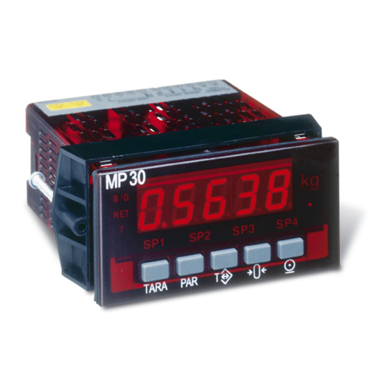
MODEL MP30 - 1/8 DIN DIGITAL WEIGHT INDICATOR
! DIRECT INTERFACE TO LOAD CELLS (4 X 350 OHM)
! FAST 20 READINGS/SEC UPDATE RATE
! DUAL RANGE INPUT: ±24 mV OR ±240 mV
! SELECTABLE 5 VDC OR 10 VDC BRIDGE EXCITATION
GENERAL DESCRIPTION
The MP30 is a high accuracy yet compact digital indicator suitable for simple
weighing and control applications. The 5 digit readout employs advanced
technology for stable, drift free readout while incorporating features that
provide application flexibility now and in the future with field plug-in option
cards. Option cards enhance the indicator functions, affording Alarm outputs,
Linear DC signal output and two-way Serial Communications.
The weight Indicator has two bipolar input ranges: ±24 mV and ±240 mV.
The built-in bridge excitation is of low-drift design and is selectable for 5 VDC
or 10 VDC output. The indicator can drive 4, 350 ohm load cells. Calibrating
the indicator is easy due to the choice of scaling procedures: Either 1) Apply
calibration weights to the weighing system or 2) Directly key-in data based
upon known load cell calibration data.
The indicator has a simple five button keypad. The key functions are: Weight
display select, Parameter Access, Tare In/Out, Acquire Zero, and Print Ticket.
Additionally, three of these keys can be programmed for different functionality.
The indicator provides readout selections of Brutto/Gross Weight, the Net
weight and the Tare Weight. The Tare Weight can be acquired automatically by
a single key-press or via a keypad direct entry.
The indicator also has a means of recording the Max and Min reading, as well
as having a Totalizer feature. The totalizer provides either a free running
accumulation of total mass flow; or keeps account of total batch weight when
adding individual ingredients.
The indicator has four setpoint outputs, implemented on Plug-in cards. The
Plug-in cards provide dual FORM-C relays (5 A), quad FORM-A relays (3 A)
or either sinking or sourcing quad open collector logic outputs. The setpoint
alarms can be configured in modes to suit a variety of control and alarm
requirements.
- High and low absolute, high and low deviation and band acting
- Balanced or unbalanced hysteresis
- On and off delay timers
DIMENSIONS In inches (mm)
! BACKLIGHTED WEIGHT UNITS INDICATOR
! PROGRAMMABLE AUTO-ZERO TRACKING
! TARE AND ZERO FUNCTIONS
! MAX AND MIN READING MEMORY
! PROGRAMMABLE INPUT AND OUTPUT RESPONSE TIMES
! INTEGRATOR/TOTALIZER
! THREE PROGRAMMABLE DIGITAL CONTROL INPUTS
! FOUR SETPOINT ALARM OUTPUTS (W/Plug-in card)
! COMMUNICATION AND BUS CAPABILITIES (W/Plug-in card)
! ANALOG OUTPUT SIGNAL (W/Plug-in card)
! PC SOFTWARE AVAILABLE FOR INDICATOR
CONFIGURATION
! NEMA 4X/IP65 SEALED FRONT BEZEL
! UNIVERSAL AC OR 24 V SUPPLY OPTION
- Auto reset or latching modes
- Reverse phase output and/or panel indicator
- Selection of alternate list of setpoint values
- Tracks gross or net weight
Plug-in cards also facilitate bus communications. These include RS232,
RS485 and DeviceNet. Readout values and setpoint alarm values can be
controlled through the bus. Additionally, the indicator has features that allow a
remote computer to directly control the outputs of the indicator. This is useful
during commissioning phases and diagnostic use. With a communication card
installed, set-up software allows configuration from a PC. The configuration
data can be saved to a file for later recall.
A linear DC output signal is available as a Plug-in card. The card provides
either 20 mA or 10 V signals. The output can be scaled independent of the input
range. The output can be used as a control or signal retransmission.
The features of the linear output card are:
- Output tracks either gross or net weight
- Programmable output update times
Once the indicator has been initially configured, the parameter list may be
locked out from further modification in its entirety or only the setpoint values
can be made accessible.
The indicator has been specifically designed for harsh industrial environments.
With NEMA 4X/IP65 sealed bezel and extensive testing of noise effects to CE
requirements, the indicator provides a tough and reliable local readout.
CAUTION: Read complete
instructions prior to installation
and operation of the unit.
Note: Recommended minimum clearance (behind the panel) for
mounting clip installation is 2.1" (53.4) H x 5.0" (127) W.
1
CAUTION: Risk of electric shock.
Advertisement
Table of Contents

Related Manuals for Minebea Intec MP30


Summary of Contents for Minebea Intec MP30
- Page 1 - Auto reset or latching modes - Reverse phase output and/or panel indicator The MP30 is a high accuracy yet compact digital indicator suitable for simple - Selection of alternate list of setpoint values weighing and control applications. The 5 digit readout employs advanced...
-
Page 2: Specifications
99999) 15. CUSTOM LINEARIZATION: 2. POWER: Data Point Pairs: Selectable from 2 to 12 115/230 V Version (MP30/00) Display Range: -19,999 to 99,999 AC Power: 85 to 250 VAC, 50/60 Hz, 15 VA Decimal Point: 0 to 0.0000 Isolation: 2300 Vrms for 1 min. to all inputs and outputs. -
Page 3: Front Panel
Safety Summary All safety related regulations, local codes and instructions that appear in the manual or on equipment must be observed to ensure personal safety and to prevent damage to either the instrument or equipment connected to it. If equipment is used in a manner not specified by the manufacturer, the protection provided by the equipment may be impaired. - Page 4 PLUG-IN CARDS full scale capacity of the system. This determines the number of leading zeros The MP30 indicator has provisions for inclusion of three plug-in option for display. The scaling range is extended up to five digits of resolution with cards.
- Page 5 AUTOMATIC ZERO TRACKING BASIC OPERATION The indicator can be programmed to automatically compensate for zero drift. TARE WEIGHT REGISTER Drift may be caused by changes in the transducers or electronics, or accumulation of material on weight systems. The indicator has a single Tare Weight register. There are two modes in which Auto-zero tracking operates whenever the readout remains within the Tare data is acquired: Pushbutton Tare and Digital Tare.
-
Page 6: Setpoint Alarms
MANUAL ZERO ACQUISITION Setpoint Alarm Values In Manual Zero operation, the Gross weight is zeroed each time the function When setpoint alarm is programmed as deviation or band acting, the effective is executed. The function is activated by a key press or user input transition. If trigger point is offset by SP1. -
Page 7: Programming Menu
PROGRAMMING MENU The programming menu of the indicator is accessed by pressing the PAR key. The menu is organized into modules, which group together parameters which are related in function. Use the arrow keys to select the module, then press PAR to enter the module. The PAR key stores the selected parameter and simultaneously indexes to the next parameter. -
Page 8: Configuration Parameters
PARAMETER MODULE 3 - Parameter and PARAMETER MODULE 4 - Secondary Function Display Lock-out Configuration Parameters Configuration Parameters DESCRIPTION/ DESCRIPTION/ DISPLAY PARAMETER RANGE AND UNITS DISPLAY PARAMETER RANGE AND UNITS COMMENTS COMMENTS Enables either Gross B-GNT is the default Brutto/Gross Display Operating Mode : Gross, Net, and OPEr... -
Page 9: Input Calibration
PARAMETER MODULE 7 - Serial Communications Parameters DESCRIPTION/ DESCRIPTION/ DISPLAY PARAMETER RANGE AND UNITS DISPLAY PARAMETER RANGE AND UNITS COMMENTS COMMENTS - None Select weight units for baUd Baud Rate Set baud rate to match UNIt Line Print Units line print. other equipment. -
Page 10: Parameter Value Chart
PARAMETER VALUE CHART Code____________ Secondary Function Parameters Input Parameters 4-SEC 1-INP FACTORY FACTORY DISPLAY PARAMETER USER SETTING DISPLAY PARAMETER USER SETTING SETTING SETTING b-6Nt OPEr rANGE 0. 0 2v MOPERATING MODE INPUT RANGE HI-t 0000. 0 dECPt 000. 0 0 MAX CAPTURE DELAY TIME DISPLAY RESOLUTION LO-t... -
Page 11: Troubleshooting
Setpoint Parameters 6-SPt FACTORY FACTORY DISPLAY PARAMETER USER SETTING DISPLAY PARAMETER USER SETTING SETTING SETTING ACt-1 ACt-3 ACTION FOR SETPOINT ACTION FOR SETPOINT 000. 0 0 000. 0 0 SP-1 SP-3 SETPOINT VALUE (main) SETPOINT VALUE (main) 000. 0 0 000. -
Page 12: Model Information
APPLICATION - Tank Level Monitor w/Alarm and Loss-of-Weight Fill This application uses the MP30 indicator to monitor the weight of a liquid storage tank. The indicator is connected directly to 4 - 350 ohm load cells, using the internal 10 VDC excitation source. The average sensitivity of the load cells are 2.1 mV/V.
Need help?
Do you have a question about the MP30 and is the answer not in the manual?
Questions and answers