Table of Contents
Advertisement
Quick Links
Advertisement
Table of Contents

Related Manuals for Minebea Intec Mini FLEXLOCK PR 6143/00N+S


Summary of Contents for Minebea Intec Mini FLEXLOCK PR 6143/00N+S
- Page 1 Installation Manual Mini FLEXLOCK PR 6143/00N+S, ../10N+S, ../15N, ../25N Translation of the Original Installation Manual 9499 053 14400 Edition 7.5.0 06/09/2020 Minebea Intec GmbH, Meiendorfer Str. 205 A, 22145 Hamburg, Germany Phone: +49.40.67960.303 Fax: +49.40.67960.383...
- Page 2 Any information in this document is subject to change without notice and does not represent a commitment on the part of Minebea Intec unless legally prescribed. This product should only be operated/installed by trained and qualiied personnel. In correspondence concerning this product, the type, name, and release number/serial number as well as all license numbers relating to the product have to be cited.
-
Page 3: Table Of Contents
Mini FLEXLOCK PR 6143/00N+S, ../10N+S, ../15N, ../25N Table of contents Table of contents Introduction............................3 Read the manual................................. 3 This is what operating instructions look like ......................3 This is what lists look like............................3 This is what menu items and softkeys look like..................... 3 This is what the safety instructions look like...................... - Page 4 Mini FLEXLOCK PR 6143/00N+S, ../10N+S, ../15N, ../25N Table of contents Certiicates ............................26 EN-2 Minebea Intec...
-
Page 5: Introduction
1 Introduction Mini FLEXLOCK PR 6143/00N+S, ../10N+S, ../15N, ../25N Introduction Read the manual Please read this manual carefully and completely before using the product. This manual is part of the product. Keep it in a safe and easily accessible location. -
Page 6: Hotline
Mini FLEXLOCK PR 6143/00N+S, ../10N+S, ../15N, ../25N 1 Introduction NOTICE Warning of damage to property and/or the environment. NOTICE indicates that damage to property and/or the environment may occur if appropriate safety measures are not observed. Take the corresponding safety precautions. -
Page 7: Safety Instructions
If there are grounds for rejection of the goods, a claim must be iled with the carrier immediately. The Minebea Intec sales or service organization must also be notiied. Before operational startup NOTICE Perform visual inspection. -
Page 8: Recommendations For Installation
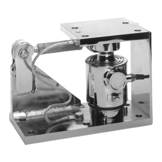
Mini FLEXLOCK PR 6143/00N+S, ../10N+S, ../15N, ../25N 3 Recommendations for installation Recommendations for installation Load cell and constrainer arrangement Examples: Do not constrain this position. Constrainer Load application Possible direction of movement To ensure the required free moving space of the weighing equipment, a maximum of three Mini FLEXLOCK kits may be used to constrain a weighing object. -
Page 9: Additional Lift-Of Protection
3 Recommendations for installation Mini FLEXLOCK PR 6143/00N+S, ../10N+S, ../15N, ../25N Round containers are the exception (image ① and ②). In this case, any number of constrainers can be installed, provided that they are tangentially aligned. The following mounting kits are available for weighing points without constrainers:... - Page 10 Mini FLEXLOCK PR 6143/00N+S, ../10N+S, ../15N, ../25N 3 Recommendations for installation The required tightening torques are given in the following table. MiniFLEXLOCK Threaded Was- Tightening Perm. overall Lifting destruc- bar/nuts torque lift-of force tive force PR 6143/00N M16-8.8 100 Nm 60 kN >75 kN...
-
Page 11: Speciications
4 Speciications Mini FLEXLOCK PR 6143/00N+S, ../10N+S, ../15N, ../25N 4 Speciications Equipment supplied 4.1.1 PR 6143/00, PR 6143/10 Description Auxiliary mounting plate Upper plate Upper load disc Constrainer with joint head (2×), screwed joint, nut (2×), bolt (2×) and locking washer (4×) -
Page 12: Pr 6143/15, Pr 6143/25
Mini FLEXLOCK PR 6143/00N+S, ../10N+S, ../15N, ../25N 4 Speciications 4.1.2 PR 6143/15, PR 6143/25 Description Axle clamp (2×) Constrainer with joint head (2×), screwed joint, nut (2×), bolt (2×) Upper load disc Upper plate Screw (2×), spring washer (2×) and washer (2×) for the equipotential bonding... -
Page 13: Dimensions
4 Speciications Mini FLEXLOCK PR 6143/00N+S, ../10N+S, ../15N, ../25N Dimensions PR 6143/00 * Right-handed thread, ** Left-handed thread all dimensions in mm Minebea Intec EN-11... - Page 14 Mini FLEXLOCK PR 6143/00N+S, ../10N+S, ../15N, ../25N 4 Speciications PR 6143/10 * Right-handed thread, ** Left-handed thread all dimensions in mm EN-12 Minebea Intec...
- Page 15 4 Speciications Mini FLEXLOCK PR 6143/00N+S, ../10N+S, ../15N, ../25N PR 6143/15 all dimensions in mm Minebea Intec EN-13...
- Page 16 Mini FLEXLOCK PR 6143/00N+S, ../10N+S, ../15N, ../25N 4 Speciications PR 6143/25 all dimensions in mm EN-14 Minebea Intec...
-
Page 17: Technical Data
4 Speciications Mini FLEXLOCK PR 6143/00N+S, ../10N+S, ../15N, ../25N Technical data PR 6143/00 PR 6143/00N PR 6143/00S Max. capacity of load cell 500 kg to 75 t 500 kg to 75 t Permissible horizontal force max. 25 kN max. 25 kN Horizontal destructive force >35 kN... - Page 18 Mini FLEXLOCK PR 6143/00N+S, ../10N+S, ../15N, ../25N 4 Speciications PR 6143/25N Max. capacity of load cell 200 t, 300 t Permissible horizontal force max. 150 kN Permissible temperature range -40°C to +100°C Material Steel galvanized, chromated and sealed (ROHS-compliant) Weight gross/net...
-
Page 19: Installation
5 Installation Mini FLEXLOCK PR 6143/00N+S, ../10N+S, ../15N, ../25N Installation Prior to mounting 5.1.1 Preparing the foundation/substructure The foundation for the mounting kit must be horizontal (use spirit level), lat, and rigid for the intended loads. The load distribution on the available load cells must be as even as possible to prevent overload of the individual load cells. -
Page 20: Tightening Torques
Mini FLEXLOCK PR 6143/00N+S, ../10N+S, ../15N, ../25N 5 Installation Tightening torques The corresponding tightening torques are given in the following table. Mounting kit Thread Washer Tightening torque PR 6143/00N M12-8.8 85 Nm PR 6143/00S M12-A2-70 60 Nm PR 6143/10N M16-8.8... -
Page 21: Pre-Assembling The Mini Flexlock And Load Cell
5 Installation Mini FLEXLOCK PR 6143/00N+S, ../10N+S, ../15N, ../25N During any additional electrical welding work near the load cell: Disconnect the load cell cables. Bypass the load cell using the lexible copper strap. Make sure that the grounding clamp of the welding set is itted as closely as possible to the welding joint. - Page 22 Mini FLEXLOCK PR 6143/00N+S, ../10N+S, ../15N, ../25N 5 Installation Small load cell radius (15 mm) Large load cell radius (35 mm) = 500 kg to 10 t = 20 to 75 t 4. Insert the load disc in the upper plate and close the assembly unit.
-
Page 23: Installing The Assembly Unit
5 Installation Mini FLEXLOCK PR 6143/00N+S, ../10N+S, ../15N, ../25N 5.3.3 Installing the assembly unit Requirements: All threaded holes are available in the foundation/substructure (see Chapter 4.2). All threaded holes for the upper plate and all through holes for the lift-of protection are available in the vessel bracket/vessel foot (see Chapter 4.2). -
Page 24: Check Mounting
Mini FLEXLOCK PR 6143/00N+S, ../10N+S, ../15N, ../25N 5 Installation Check mounting When all mounting kits have been installed, check them for proper mounting. In particular, force shunts should be avoided. It is essential to check: whether the auxiliary mounting plate (4) has been removed. -
Page 25: Cleaning
6 Cleaning Mini FLEXLOCK PR 6143/00N+S, ../10N+S, ../15N, ../25N Cleaning The mounting kit is easy to clean. It can be spray-washed with water. For this purpose, spray the water jet from top to bottom and around the mounting kit. NOTICE Some cleaning agents may not be compatible with the mounting kit material. -
Page 26: Disposal
Mini FLEXLOCK PR 6143/00N+S, ../10N+S, ../15N, ../25N 7 Disposal Disposal If the packaging is no longer required, please take it to your local waste disposal facility and/or a reputable disposal company or collection point. The packaging largely consists of environmentally friendly materials which can be used as secondary raw materials. -
Page 27: Spare Parts And Accessories
8 Spare parts and accessories Mini FLEXLOCK PR 6143/00N+S, ../10N+S, ../15N, ../25N Spare parts and accessories Replacement parts Description Max. capacity Order no. Lower load disc with supporting ring, default 500 kg…10 t 5322 693 91164 Lower load disc with supporting ring, default 20…75 t... - Page 28 Mini FLEXLOCK PR 6143/00N+S, ../10N+S, ../15N, ../25N 9 Certiicates Certiicates Ser. no. Description Document no. CE marking CE-PR 6143 Declaration of Performance 002/2019 Conformity of the Factory Produc- 2451-CPR-EN1090-2014.2089.004 tion Control EN-26 Minebea Intec...
- Page 29 European Standard EN 1090 Since July 2014, load-bearing parts made of steel have required EN 1090 certiication to obtain general technical approval. The standard applies in he following countries: Belgium, Bulgaria, Denmark, Germany, Estonia, Finland, France, Greece, Ireland, Iceland, Italy, Croatia, Latvia, Lihuania, Luxembourg, Malta, he Neherlands, Norway, Austria, Poland, Portugal, Romania, Sweden, Switzerland, Slovakia, Slovenia, Spain, he Czech Republic, Hungary, he United Kingdom and Cyprus...
- Page 30 The mounting kit is used in combination with a PR6201/PR 6203/PR 6204 load cell for container and silo weighing. Manufacturer in accordance with Minebea Intec GmbH Article 11, Paragraph 5: Meiendorfer Strasse 205 A 22145 Hamburg, Germany System to evaluate and check the...
- Page 31 7. The manufacturer in accordance with number 4 is solely responsible for creating this performance declaration. Signed for the manufacturer and on behalf of the manufacturer by: Minebea Intec GmbH Hamburg, November 19, 2019 Wolf Dieter Schulze...
- Page 36 Published by Minebea Intec GmbH | Meiendorfer Strasse 205 A | 22145 Hamburg, Germany Phone: +49.40.67960.303 | Email: info@minebea-intec.com www.minebea-intec.com...
Need help?
Do you have a question about the Mini FLEXLOCK PR 6143/00N+S and is the answer not in the manual?
Questions and answers