Sign In
Upload
Manuals
Brands
Minebea Intec Manuals
Scales
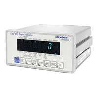
CSD-903-P25
Minebea Intec CSD-903-P25 Manuals
Manuals and User Guides for Minebea Intec CSD-903-P25. We have
1
Minebea Intec CSD-903-P25 manual available for free PDF download: Operating Instructions Manual
Minebea Intec CSD-903-P25 Operating Instructions Manual (244 pages)
Brand:
Minebea Intec
| Category:
Accessories
| Size: 1 MB
Table of Contents
Table of Contents
3
Introduction
11
Read the Manual
11
This Is What Operating Instructions Look Like
11
This Is What Lists Look Like
11
This Is What Menu Items and Softkeys Look Like
11
This Is What the Safety Instructions Look Like
11
Hotline
12
Safety Instructions
13
General Information
13
Intended Use
13
For Safe Operation
13
Location of Installation
13
Installing the Instrument
14
Power Supply
16
Operating Precautions
16
Conformed Standards
17
Names and Functions of Parts
19
Front Panel
19
Rear Panel
21
Side
22
Wiring
23
Precautions for Wiring
23
Connection with Load Cells
23
6-Wire Connection Cable
24
4-Wire Connection Cable
25
Connecting Load Cells in Parallel
26
Connection with Power Supply and the Ground
27
Connecting the External Control I/O
28
Input Connection
28
Output Connection
29
Connecting to a 2-Pin Method Serial Interface
29
Operating
31
Character Display Pattern
31
Mode Changeover
31
Function Settings Table
33
Calibration
37
Calibration Setting Items
37
Parameters to be Set Where Necessary after Calibration
37
Calibration Procedures
39
Calibration Low
39
Switch to Calibration Mode
40
Set the Scale Interval
40
Set the Maximum Load
41
Setting the Mass of the Weight
41
Zero Point Calibration
42
SPAN Calibration
43
Quit Calibration
45
Fine Calibration of Zero and SPAN
45
Switch to Zero and SPAN Ine Calibration Mode
45
Digital Linearization
48
Switch to Digital Linearization Mode
48
Setting Digital Linearization
48
Calibration of Zero Point Only
50
Switch to Calibration Mode by Zero Point
50
Calibration of the Zero Point Only
50
CAL-Switch
51
Function Mode
53
C Function Mode Setting Method
53
C Function Data Functions
54
Various Operations by C Function Data
58
Decimal Point Display Position
58
A/D Sampling
58
Overload Display Condition (OL, -OL Display)
58
Unit
58
Excitation
58
Net Weight Sign Reversal Function
59
Zero Set
59
Operating Condition of ZERO Set
59
Zero Set Efective Range
59
ZERO Tracking
60
ZERO Tracking Target
60
ZERO Tracking Data Width
60
ZERO Tracking Duration
60
Power on Zero
61
Power on ZERO Operation
61
Tare Weight Cancellation
61
Tare Weight Cancellation Operating Conditions
61
Clear at Power on
62
Setting in Set Mode 2 or Preset Tare Weight Set
62
Stability Detection
62
Unit Display in the Sub-Display Section
62
Gravity Acceleration Compensation
62
Setting Method for Gravity Acceleration Compensation Value
62
District Number for Place of Use (When CF-25 = 0)
63
District Number for Place of Calibration (When CF-25:0)
63
Acceleration Due to Gravity for Place of Use (When CF-25:1)
63
Acceleration Due to Gravity for Calibration Location (When CF-25:1)
63
Automatic Range Switch
64
Setting the Range Switch Operation
64
Setting the Scale Interval of the Second Range
64
Setting the Limit Value for the Second Range
65
Setting the Scale Interval of the Third Range
65
Setting the Limit Value for the Third Range
65
Stability Detection Duration During Calibration
66
Digital Linearization Clear
66
Memory Clear
67
Function Mode
68
Function Mode Setting Method
68
Details of Function Data
69
Various Operations by Function Data
78
Digital Ilter
78
Analog Ilter
78
Display Frequency
78
Stabilization Ilter
78
Stabilization Ilter Data Width
78
Stabilization Ilter Time Range
78
Key Lock Function
79
Key Lock 1
79
Key Lock 2
80
Stability Detection
80
Stability Detection Data Width
80
Duration of Stability Detection
80
Preset Tare Weight Cancellation Input
81
Preset Tare Weight Cancellation Operating Condition
81
Net Weight Ofset Operation
82
Print Command
82
Print Operation Status
82
Hold
82
HOLD Operation
82
HOLD Target
82
Sub-Display Section
83
Sub-Display Section Value Selection
83
Accumulation
84
Accumulation Function Operating Condition
84
Execute Accumulation
84
Display Range for Accumulated Value and Count
85
Clear Accumulation Value and Accumulation Times
85
Brands (Products)
86
Brand Changeover
86
Brand Number
86
F Key Settings
86
External Control I/O Settings
87
External Control Input Setting Method
87
External Control Output Setting Method
88
Memory Clear
89
Weighing Mode
90
Weighing Mode Setting Method
91
Setting Mode
92
Weighing Comparison Value 1 Setting Mode
92
Weighing Comparison Value 2 Setting Mode
95
Simple Mode
97
Simple Batch Mode
97
Simple Discharge Mode
99
Sequential Mode
100
Sequential Batch Mode (Batch In)
100
Sequential Batch Mode (Batch Out)
102
Supplementary Batch (Discharge) Mode
104
Automatic Overshoot Compensation
106
4-Steps Check Mode 1
107
S1, S2, S3 and S4 Comparison Operation
107
Comparison Targets for S1, S2, S3 and S4 in Check Mode
108
Operation of S0 in Control Mode
109
Hysteresis in Check Mode
111
4-Steps Check Mode 2
112
Comparison Targets for S1, S2, S3 and S4 in Check Mode
113
S1, S2, S3 and S4 Comparison Operation
113
Hysteresis in Check Mode
113
SQ Function Mode
115
SQ Function Mode Setting Method
115
Function of SQ Function Data
116
Various SQ Function Data Functions
119
Weighing Mode
119
Control Mode
119
Comparison Signal Operation
119
Near Zero (ZERO BAND) Comparison Operation
119
Full Comparison Operation
119
Batch Monitoring Timer
119
Batch Start Time Operation Setting
120
Start above Near Zero at the Time of Batch Start
120
Automatic Tare Weight Cancellation at Batch Start
120
Batch Start Delay Timer
120
Automatic Tare Weight after Batch Start Delay Timer
120
Coarse) Low Comparison Stop Timer
120
Middle) Low Comparison Stop Timer
120
Fine) Low Comparison Stop Timer
120
Flow/Discharge Brand Setting Target
121
Automatic Overshoot Correction
121
Automatic Overshoot Correction Setting
121
Automatic Overshoot Correction Width
121
Save Automatic Overshoot Value
121
Judgment Condition
121
Calming Time
121
Post-Batching Operation Setting
122
Maximum Time of Post-Batching
122
Judgment Condition after Post-Batching
122
Post-Batching Time
122
Calming Time after Post-Batching
122
Weighing Inish Output Operation Setting
122
Batch Inish Signal Output Time
122
Batch Inish Output off
122
Discharge Operation Setting after Weighing Inish
123
Discharge Start at Weighing Inish
123
Discharge Monitor Timer
123
Discharge Gate Close Delay Time
123
Discharge Inish Output Time
123
Tare Weight Cancellation at Discharge Inish
123
Accumulation Clear
123
SQ Function Clear
124
Storage Location of Setting Data
125
Data Stored in Internal RAM
125
Data Stored in EEPROM
125
Change the Storage Location for Data
125
Check Mode
126
Check Mode Setting Method
126
Ezcts Mode
127
Conirmation of ROM Version
128
Conirmation of Options
128
Conirmation of External Control Input
128
Conirmation of External Control Output
129
Conirmation of Load Cell Output Voltage
130
Conirmation of BCD Output
131
Conirmation of Analog Output
131
15 2-Pin Method Serial Interface (S-I/F)
133
Interface Speciication
133
Data Format
133
Explanation of Format Data
134
Explanation of Output Type
134
Standard RS-485 Communication
135
Speciications for Standard RS-485 Communications
135
Data Format
135
Standard RS-485 Communication Settings
135
Operation Mode
135
Speciications of Communication by RS-485
136
Address Setting
136
Delay Time of RS-485 Return Data
136
Transmission Data Decimal Point Detection
137
Interface Stream Mode Output Target
137
Connecting Method
137
One to One
137
One to N
138
Modbus Communication
139
Calibration by Transmission through Modbus Interface
154
Calibration Mode
154
Zero and SPAN Ine Calibration Mode
158
Calibration Mode for Digital Linearization
161
Calibration of Zero Point Only
165
Options
167
Analog Output
167
Current Output Speciications (Model: CSD-903-P07)
167
Voltage Output Speciications (Model: CSD-903-P25)
167
Connection of Analog Output
168
Analog Output Target
168
Scaling of Analog Output
168
Analog Output Ine Calibration
170
BCD Output
171
Speciications (Model CSD-903-P15)
171
Operation Mode of BCD Output
171
BCD Output Target
171
Logic of BCD Output
172
Width of P.C. (Print Command)
172
BCD Output Times
172
Pin Assignment of the BCD Output
172
I/O Equivalent Circuits
174
Timing Chart
174
Output Condition
175
RS-232C and RS-422/485 Interface
175
RS-232C Interface Speciication (P/N: CSD-903-P74)
175
RS-422/485 Interface Speciication (P/N: CSD-903-P76)
176
Operation Mode of RS-232C and RS-422/485
176
Output Target Synchronized with RS-232C Print for RS-232C and RS-422/485
177
Communication Speciications by RS-232C and RS-422/485
178
Address Settings for the RS-422/485 Interface
178
Changeover of RS-422/485
178
Delay Time for RS-485 Return Data
178
Transmission Data Decimal Point Usage for RS-232C and RS-422/485
178
Pin Assignment of the RS-232C Interface
179
Pin Assignment of the 422/485 Interface
180
Data Format of Command Mode
183
Data Format Synchronizing with Data Format in Stream Mode
205
Data Format Communication Calibration
207
Maintenance
218
Lifetime of Used Parts
218
Replacing the Fuse
218
Troubleshooting
220
Execute Trouble Shooting
220
Error Display and Buzzer Sound
232
Error Display
232
Error Sub-Display
233
Sequence Error Display
233
Appendix
235
Customer Service
235
Speciications
235
Analog Speciications
235
Display Speciications
235
Interfaces
237
General Speciications
239
Standard Shipping Speciications
240
Accessories
240
Data Format of Command Mode
241
Data Format Synchronizing with Data Format in Stream Mode
241
Advertisement
Advertisement
Related Products
Minebea Intec CSD-903-P07
Minebea Intec CSD-903-P15
Minebea Intec CAIS2
Minebea Intec CAIS3
Minebea Intec CAW3S
Minebea Intec CAWISL3
Minebea Intec CAH1E
Minebea Intec CAH3E
Minebea Intec Compact Scale Puro Advanced Series
Minebea Intec Compact Scale Puro Advanced EF-P1
Minebea Intec Categories
Scales
Accessories
Cable Box
Racks & Stands
Industrial Equipment
More Minebea Intec Manuals
Login
Sign In
OR
Sign in with Facebook
Sign in with Google
Upload manual
Upload from disk
Upload from URL