Table of Contents
Advertisement
Quick Links
Advertisement
Table of Contents

Related Manuals for Minebea Intec PR 6241


Summary of Contents for Minebea Intec PR 6241
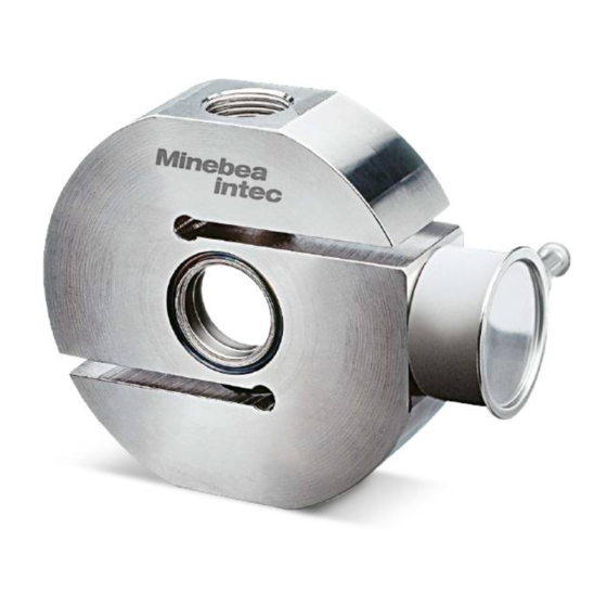
- Page 1 Installation Manual Compression Load Cell S-Type PR 6241 Translation of the Original Installation Manual 9499 053 27900 Edition 1.7.0 09/04/2019 Minebea Intec GmbH, Meiendorfer Str. 205 A, 22145 Hamburg, Germany Phone: +49.40.67960.303 Fax: +49.40.67960.383...
- Page 2 Any information in this document is subject to change without notice and does not represent a commitment on the part of Minebea Intec unless legally prescribed. This product should be operated/installed only by trained and qualiied personnel. In correspondence concerning this product, the type, name, and release number/serial number as well as all license numbers relating to the product have to be cited.
-
Page 3: Table Of Contents
Compression Load Cell S-Type PR 6241 Table of contents Table of contents Introduction............................3 Read the manual................................. 3 This is what operating instructions look like ......................3 This is what lists look like............................3 This is what menu items and softkeys look like..................... 3 This is what the safety instructions look like...................... - Page 4 Compression Load Cell S-Type PR 6241 Table of contents Visual inspection...............................20 Metrological controls ...............................20 8.3.1 Checking the zero output signal of the load cell..................20 8.3.2 Checking the strain gauge bridge of the load cell ..................20 8.3.3 Checking the insulation impedance of the load cell..................21 8.3.4...
-
Page 5: Introduction
1 Introduction Compression Load Cell S-Type PR 6241 Introduction Read the manual Please read this manual carefully and completely before using the product. This manual is part of the product. Keep it in a safe and easily accessible location. This is what operating instructions look like 1. -
Page 6: Hotline
Compression Load Cell S-Type PR 6241 1 Introduction NOTICE Warning of damage to property and/or the environment. NOTICE indicates that damage to property and/or the environment may occur if appropriate safety measures are not observed. Take the corresponding safety precautions. -
Page 7: Safety Instructions
Intended use The load cell PR 6241 has been designed especially for weighing small and medium sized process vessels and for high-precision illing. The load cell PR 6241 may only be used as intended for weighing tasks. -
Page 8: Recommendations For Installation
Compression Load Cell S-Type PR 6241 3 Recommendations for installation Recommendations for installation Load cell and constrainer arrangement Examples: Do not constrain this position. Constrainer Load application Possible direction of movement EN-6 Minebea Intec... -
Page 9: Additional Lift-Of Protection
3 Recommendations for installation Compression Load Cell S-Type PR 6241 The supporting structure of the scale (i.e. the load cell support) and the vessel must be stable enough to withstand the speciied loads, be horizontal (water level!) and lat. Vessels should preferably be supported by 3 load cells (see igure). -
Page 10: Selecting Maximum Capacity
Compression Load Cell S-Type PR 6241 3 Recommendations for installation Assembly: Mount the threaded bar (1) so that it has suicient free moving space in the drill hole. Lock the nuts (2) so that there is a remaining distance A* from the washer (3). -
Page 11: Speciications
4 Speciications Compression Load Cell S-Type PR 6241 4 Speciications Equipment supplied with the load cell Description Flexible copper strap Load cell The following are not shown: Quick guide Calibration Certiicate General information Load cell material Stainless steel 1.4542 acc. to DIN EN 10088-3 Protection against en- Hermetically sealed by welding. -
Page 12: Possible Marking Of The Load Cell For The Ex Area
Compression Load Cell S-Type PR 6241 4 Speciications Cable length Cable gauge 4×0.35 mm Cable bend radius ≥25 mm (ixed installation) ≥75 mm (lexible installation) Cable sheath material Thermoplastic elastomer (TPE) Cable sheath color Gray (standard version) Blue (Ex version) -
Page 13: Dimensions
4 Speciications Compression Load Cell S-Type PR 6241 4.4 Dimensions all dimensions in mm Model A [mm] B [mm] C [mm] D [mm] E [mm] PR 6241/12–52 PR 6241/13–23 PR 6241/33 M20×1.5 PR 6241/53 M20×1.5 Ordering information Model Max. capacity... -
Page 14: Technical Data
Compression Load Cell S-Type PR 6241 4 Speciications Technical data Designation Description Abbr. D1 Unit Accuracy class 0.04 0.015 0.008 Minimum dead load lowest limit of speciied measu- ring range Maximum capacity highest limit of speciied mea- See Chapter suring range... - Page 15 4 Speciications Compression Load Cell S-Type PR 6241 Designation Description Abbr. D1 Unit Max. supply voltage permissible for continuous ope- ration without damage for PR 6241/..E: Nominal ambient to hold the speciied perfor- °C -10…+55 temp. range mance Usable ambient temp.
- Page 16 Compression Load Cell S-Type PR 6241 4 Speciications NTEP: min. scale interval of the load cells v for PR 6241/13… … PR 6241/53 Type Divisions Unit Class III D1/D1E 2000 1000 multiple C3/C3E 5000 C6/C6E 8000 … Class III L...
-
Page 17: Installation
5 Installation Compression Load Cell S-Type PR 6241 Installation Safety instructions NOTICE Welding or lightning strike current lowing through the cell can damage it. All electrical welding on the weighing system must be inished before mounting the load cells. When installing the load cell, immediately bypass the load cell with the lexible copper strap provided for this purpose (included in the equipment supplied, see Chapter 4.1). -
Page 18: Connection
Compression Load Cell S-Type PR 6241 6 Connection Connection General information NOTICE The load cell cable end is protected against contamination and moisture by a protective sheathing. The protective sheathing should only be removed shortly before connecting! Protect the cable ends against contamination. Moisture must not get into the open end of the cable. -
Page 19: Load Cell Cable
6 Connection Compression Load Cell S-Type PR 6241 6.2.1 Load cell cable The load cell cables are inseparably connected to the load cells in the factory and their individual resistance and temperature efect are equalized with the load cells. Therefore, never shorten the cables, rather simply roll up the extra length and secure it. - Page 20 Compression Load Cell S-Type PR 6241 6 Connection EN-18 Minebea Intec...
-
Page 21: Preparing For Calibration
For calibration of the measuring system, please refer to the manual of the corresponding indicator. Smart Calibration When using Minebea Intec devices, we recommend always running "Smart Calibration" irst. This allows all required values to be extracted from the Calibration Certiicate supplied. -
Page 22: Troubleshooting
Compression Load Cell S-Type PR 6241 8 Troubleshooting Troubleshooting General Notes The following hints will enable a technician to do an initial diagnostic or help in case of incorrect or non-reproducible weighing results after commissioning and calibration. Visual inspection Component... -
Page 23: Checking The Insulation Impedance Of The Load Cell
8 Troubleshooting Compression Load Cell S-Type PR 6241 Type Input impedance Output impedance (red core, blue core) (green core, gray core) 650 Ω ±6 Ω 610 Ω ±1 Ω C3, C6 650 Ω ±6 Ω 610 Ω ±0.5 Ω 8.3.3... -
Page 24: Maintenance/Repairs/Cleaning
Of-shore all-weather protection spray can be applied extensively to the load cell in aggressive environments. Repairs The load cell PR 6241 is designed to be as robust as possible for the required measuring accuracy and is highly reliable. Should an electrical or mechanical defect nevertheless occur, the load cell must be replaced. -
Page 25: Disposal
10 Disposal Compression Load Cell S-Type PR 6241 10 Disposal If the packaging is no longer required, please take it to your local waste disposal facility and/or a reputable disposal company or collection point. The packaging largely consists of environmentally friendly materials which can be used as secondary raw materials. -
Page 26: Spare Parts And Accessories
Compression Load Cell S-Type PR 6241 11 Spare parts and accessories 11 Spare parts and accessories 11.1 Replacement parts Description Max. capacity Order no. Flexible copper thread, 250 mm long 5312 321 28056 Load disc kit (incl. O-ring) 5312 693 98132 100 kg…2 t... -
Page 27: Load Discs
Cable junction boxes We recommend using the following junction boxes: Description Order no. PR 6130/04 (aluminum, 1–4 load cells, IP67; not for PR 6241/..E) 9405 361 30044 PR 6130/08 (polycarbonate, 1–8 load cells, IP65; not for PR 6241/..E) 9405 361 30084 PR 6130/34Sa (1.4301, 1–4 load cells, IP68, IP69, veriiable;... -
Page 28: Connexx Module
Compression Load Cell S-Type PR 6241 11 Spare parts and accessories 11.2.5 Connexx module 11.2.5.1 Speciications 11.2.5.1.1 Equipment supplied Description Connexx module incl. retaining plate (1a) Not shown: Fixing bracket incl. knurled screw Washers (4×; for various screw sizes) Rail holder 11.2.5.1.2 Dimensions... - Page 29 11 Spare parts and accessories Compression Load Cell S-Type PR 6241 11.2.5.2 Connection of Connexx modules The load cell is irmly attached to the Connexx module. The load cell cable is 0.7…1.0 m long. The mounting options for the module are described in Chapter 11.2.5.3.
- Page 30 Compression Load Cell S-Type PR 6241 11 Spare parts and accessories Connection example, shown as a diagram ① Potential equalization ② Terminating resistor ③ D-Sub 9-pin plug connector, male ④ D-Sub 9-pin plug connector, fe- male ⑤ 24 V DC input voltage (only for...
- Page 31 When using a retaining plate, the Connexx module is attached to the weighing device (e.g. the leg of a container). Note: Minebea Intec recommends using a stainless-steel cable tie when mounting using a retaining plate. Thread the stainless-steel cable tie through the lugs (1) on the retaining plate (2) and attach to the weighing device.
- Page 32 Compression Load Cell S-Type PR 6241 11 Spare parts and accessories 11.2.5.3.2 Mounting using a ixing bracket When using a ixing bracket, the Connexx module is attached to the mounting kit. Place the ixing bracket (1) on the lower plate (2) of the mounting kit.
- Page 33 11 Spare parts and accessories Compression Load Cell S-Type PR 6241 2. Depending on the mounting kit, bend the appropriate lugs (1a) downwards using a tool to prevent the ixing bracket from twisting. 3. Slide the ixing bracket (1) onto the lower plate (2) of the mounting kit.
- Page 34 Compression Load Cell S-Type PR 6241 11 Spare parts and accessories 5. Mount the Connexx module (5) on the ixing bracket (1). 6. Tighten the knurled screw (6) by hand to ix the module in place. EN-32 Minebea Intec...
- Page 35 11 Spare parts and accessories Compression Load Cell S-Type PR 6241 11.2.5.3.3 Mounting using a mounting rail holder When using a mounting rail holder, the Connexx module is attached to the weighing device (e.g. frame with a mounting rail). Remove the screw (3).
- Page 36 Compression Load Cell S-Type PR 6241 11 Spare parts and accessories 11.2.5.4 Connecting parts for the Connexx module To connect the Connexx module, the following connecting parts are required: Description Order no. PR 5510/05 CANopen interface for PR 5410 9405 355 10051 PR 6154/03 Connexx connecting kit for three load cells (comprising: 2×...
-
Page 37: Appendix
12 Appendix Compression Load Cell S-Type PR 6241 12 Appendix 12.1 Certiicates/safety instructions/control drawing Ser. no. Description Document no. EC-Type Examination Certiicate BVS 16 ATEX E 005 Certiicate of Conformity IECEx BVS 16.0005 EU-Type Examination Certiicate TÜV 03 ATEX 2301X Certiicate of Conformity IECEx TUN 17.0025X... - Page 38 Published by Minebea Intec GmbH | Meiendorfer Strasse 205 A | 22145 Hamburg, Germany Phone: +49.40.67960.303 | Email: info@minebea-intec.com www.minebea-intec.com...
Need help?
Do you have a question about the PR 6241 and is the answer not in the manual?
Questions and answers