
Related Manuals for Pima CAPTAIN-i 4410061


Summary of Contents for Pima CAPTAIN-i 4410061
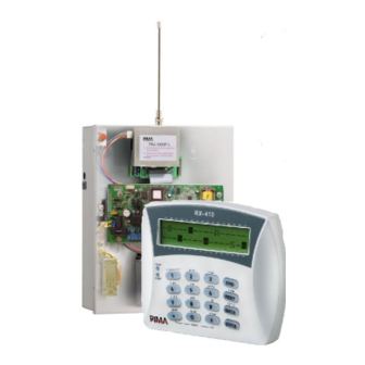
- Page 1 PIMA Electronic Systems Ltd. www.pima-alarms.com XX en Rev: K Part No: October 2008 4410061 CAPTAIN-i ONES NTRUDER LARM YSTEM NSTALLATION UIDE System ver. 6.0...
-
Page 2: Default Codes
PIMA’s prior written consent is granted. All efforts have been made to ensure that the content of this manual is accurate. Pima retains the right to modify this manual or any part thereof, from time to time, without serving any prior notice of such modification. -
Page 3: Table Of Contents
Captain-i - Installation Guide Table of Contents Chap 1. Introduction..................5 Release Note - Version 6.0 ..............5 Main features ...................6 The Dialer..................6 The LCD Keypad................7 The PCB ..................7 Chap 2. Partitions ..................9 Chap 3. Connecting Accessories..............10 Zone Inputs ................... 10 Initial operations &... - Page 4 Captain-i - Installation Guide Reporting codes (phone)..............46 Reporting codes (radio) ..............47 Appendix B – Programming formats ............48 Pulse formats ................. 48 DTMF formats ................49 Appendix C – Entering names ..............51...
-
Page 5: Chap 1. Introduction
Captain-i - Installation Guide Chap 1. Introduction This guide provides the installation, wiring and programming instructions for PIMA’s CAPTAIN-i intruder alarm system. CAPTAIN-i has many features that fits customer’s individual needs, and yet it remains easy to install and simple to program and use, both by the end-user and the installer. -
Page 6: Main Features
Captain-i - Installation Guide Main features ♦ 6 zone intruder alarm panel ♦ Can be divided to 2 partitions ♦ Up to 4 telephone numbers to the Monitoring Station and 3 to private numbers ♦ Easy to install and simple to program and use ♦... -
Page 7: The Lcd Keypad
Captain-i - Installation Guide The LCD Keypad CAPTAIN-i is fully controlled by the LCD keypad. The PCB CAPTAIN-i PCB 1.5.1 Fuses ♦ F1 - Siren power supply (0.9A) ♦ F2 - Keypad and detectors power supply (750mA). This fuse protects all the (+V) outputs ♦... - Page 8 The system can have up to 6 keypads connected to it. Notes: All PIMA LED keypads can be connected to the system. Do not connect anything but keypads to the keypad power source connectors ♦ SRN: Siren Output: Two sirens (with or without driver) in parallel can be connected to this output (See section “...
-
Page 9: Chap 2. Partitions
Captain-i - Installation Guide Chap 2. Partitions CAPTAIN-i can be configured into 2 partitions with the following settings: 1. Each zone and each user can be assigned to one of the two partitions or both 2. Each partition can have a different subscriber (account) ID 3. -
Page 10: Chap 3. Connecting Accessories
Captain-i - Installation Guide Chap 3. Connecting Accessories IMPORTANT! Disconnect all power supply before installation Connecting accessories scheme (optional) Zone Inputs Any zone connected to the system can be set as EOL zone. Note: CAPTAIN-i can only be set as an EOL (one or two) protected system, and not each zone separately, i.e., all zones are set as EOL zones. - Page 11 Captain-i - Installation Guide 3.1.2.1 N.C. PIR Control Zone Panel ( ) R1 or R1 or R3 Tamper N.C. TAMPER RELAY switch Detector Detector EOL connected to EOL in serial to a relay The relay and the tamper are N.C PIR (zone) and a connected, each with an EOL;...
- Page 12 Captain-i - Installation Guide 3.1.4 Arming with key/Remote control Connect the key or relay output of the remote control receiver to Zone 6 and GND. Zone 6 must be programmed as normally open and as Key input (see section 5.4.4). For better protection it is recommended to connect a 10KΩ...
- Page 13 Captain-i - Installation Guide 3.1.5.2 Horn ♦ Connect the horn to the SRN and common (-) terminals ♦ Program the siren tone (see section 5.4.1) Horn (speaker siren) 3.1.5.3 Low current up to 200mA DC Siren ♦ Connect the siren’s GND end to the SRN terminal and siren’s power to the (+)V terminal ♦...
-
Page 14: Keypad Connection
Captain-i - Installation Guide 3.1.6 Keypad connection Connect all 4 wires coming from the keypad ([-], +V, IN, OUT) to the keypad terminal block. IMPORTANT! The keypad power should not be shared with any other device! The keypad wires should not be passed through the same cable as the telephone wires. - Page 15 Captain-i - Installation Guide 3.1.9 Programming the VU-20N 1. Navigate to “System config 3” menu (#8) and mark ‘+’ under ‘V - Voice’ unit and under ‘G - Delayed PGM 2. In Zone responses menu (#3), click the desired zone and mark ‘+’ under ‘P - PGM’, so that the zone will trigger the PGM output (to which the VU-20N connects) in alarm.
-
Page 16: Initial Operations & Programming Devices
Captain-i - Installation Guide Connect the 3 wires to the connection terminals of the transformer housing. Be sure to connect them in the correct order. Check for continuity between the control unit grounding point and the electrical plug grounding point with an ohmmeter. The resistance must be less than 1Ω. -
Page 17: Chap 4. Programming Options
COMAX Up/Download remote programming with a PC and modem; Local loading with a computer and COMAX. Remote Programming with COMAX The CAPTAIN-i can be programmed remotely via a telephone line using PIMA’s COMAX software. COMAX is upload/download & control software and it enables programming of all parameters, memory check, arming, disarming, etc. -
Page 18: Lcl-11A: Adaptor For Local Programming
Captain-i, Installation Guide Note: To connect TC-3 with an LCD keypad to the RXN-406 or to connect PRG-22 to RXN-400/410, the keypad’s cover should be first removed as the RJ-11 connector is internal. LCL-11A: Adaptor for Local Programming The LCL-11A unit is used for programming CAPTAIN-i using PC and COMAX Upload/Download software. - Page 19 Captain-i Installation Guide The following pages provide detailed instructions of each function. CAPTAIN-i factory default codes are as follows: Primary (Master) Code: 5555 Technician Code: 1234 Some of the screens appear as an “options bar” in which you must determine whether certain option will be enabled (+) in the system or disabled (-).
- Page 20 Captain-i, Installation Guide Function Page Subscriber ID (telephone and radio, station format, auto tests) GSM Unit Report codes (telephone) Report codes (radio) Monitoring Station telephone numbers Telephone line connection characteristics (number of rings) Siren and SMOKE output parameters (type of ring and time of siren) System configuration (6 screens) Config 1 –...
-
Page 21: Chap 5. Programming
Captain-i Installation Guide Chap 5. Programming To enter technician menu, the technician code (default: 1234) must be entered. In all the next sections, though not shown, this code is entered at the beginning of every step. Also demonstrated in the first section is the ‘Select’ menu. 5.1.1 Zone sensitivity Select:... -
Page 22: Zone Name
Captain-i, Installation Guide Par. Full name Description Entry Delayed opening this zone will start the Exit or Entry time Note: A zone defined as entry-delayed or zone-follower is also exit-delayed Entry Follower The zone will not cause an alarm if any delayed zone is open. -
Page 23: Communication Parameters
Captain-i Installation Guide Communication Parameters 5.2.1 Communication with the monitoring station CAPTAIN-i enables event reporting to the Central Monitoring Station (CMS) by telephone, GSM, and/or radio. A unique code can be programmed for each event in accordance with Monitoring Station and/or customer requirements, such as a response code to tampering with the box or to define zone number 5 as the zone connected to a Distress button. - Page 24 A subscriber number of 0 is as if no subscriber number was programmed, and thus there is no communication with the Monitoring Station The largest subscriber number for PIMA format is 8000 (for other formats, this depends on the specific format)
-
Page 25: Auto Test
Captain-i Installation Guide 5.2.6 Setting CMS format The CAPTAIN-i enables communication with various Monitoring Stations. The format definition determines the method of communication between the system and the Monitoring Station. See Appendix B – Programming formats on page 48 for a description of the possible formats, and select the format that is suitable for the specific Monitoring Station. -
Page 26: Gsm-200
Captain-i, Installation Guide 5.2.9 Auto test interval The system will perform an automatic self-check with the Monitoring Station at set intervals. This parameter sets the number of hours between checks, such as every two hours. Note: In case you will define a test hour and a time interval for tests, the system will run a test at the preset hour and between the time intervals you defined Auto test time X6 :... -
Page 27: Report Codes (Telephone)
Captain-i Installation Guide Notes: When the alarm system identifies a failure in the PSTN line, the events are immediately transmitted through the GSM (including arming/disarming) regardless of the “E” parameter. While sending events via GSM, the system continues trying to send them via PSTN line. -
Page 28: Monitoring Station Telephone Numbers
Captain-i, Installation Guide Code Report AC/RESTR AC failure/Restore LB/RESTR Low battery failure/Restore PF/RESTR Low card voltage (less than 9V)/ Restore PH/RESTR Telephone failure/ Restore Test code (automatic, manual, remote) Panic code (pressing both keys) FUS/RESTR Detector power failure/ Restore ONG/OFG System armed with a non-user code (short code, for example)/ System disarmed with a non-user code ON1/OFF1 -... -
Page 29: Programming System Characteristics
Captain-i Installation Guide After setting “Telephone 4,” the display will show “Pre Number.” The installer may program one or more digits to be dialed before all the above four Monitoring Station telephone numbers. Programming this screen increases the number of digits available for the Monitoring Station telephone numbers from 16 to 22. - Page 30 Captain-i, Installation Guide Notes: Scroll through the various functions with Marking “+” under a parameter enables it. Marking a “-” disables it. In order to change the mark from “-” to “+” (and vise versa) use To confirm, Par. Descr. Settings Telephone The system will perform all the functions associated...
- Page 31 “+”: Restore of zone after alarm is reported. Reports which zones have been closed and which are still open after siren stops. Note: Do not use this parameter with PAF (PIMA) format Tone “+” The system will dial using tones.
- Page 32 Captain-i, Installation Guide Par. Descr. Settings screen (see section Zone responses on page 22), and (2) a “+” must be set under the G (PGM Delayed) in the Config. 3 screen (the current screen) Zone 6 Key “-” Defines Zone 6 as connected to a key Key Type “-“...
-
Page 33: Siren And Smoke Output Parameters
Captain-i Installation Guide Par. Descr. Settings Invert Smoke The smoke output will work in an inverted manner from the ordinary situation, i.e. when a “+” is displayed under the letter S, the smoke output is disengaged in an ordinary situation, and during an event (if thus programmed), the smoke output will be switched to GND. -
Page 34: System Responses To Faults And Events
Captain-i, Installation Guide LED Keypad Used RX-180, RXN-200 RX-6 / RX-406 Not Used Table 5. Selecting Keypad Type 5.4.7 System configuration 6 (config 6) PDX User 8=Panic Config 6 X6 : User code #8 as panic code Par. Descr. Settings Panic “+”... -
Page 35: Delay Times (Enter, Exit)
Captain-i Installation Guide Par. Descr. Settings Siren “+” The siren is triggered Communication “+” The system will dial and/or send radio transmission to the CMS and the private account. Buzzer “+” keypad buzzer activated “+” PGM output is triggered SPBG Siren ---- Phn.fail... -
Page 36: General Issues
Captain-i, Installation Guide 5.4.10 Setting exit delay time , the display will show: “Delay times", and the display will show: "Exit Delay time:” enter the required delay time in seconds (up to 250 seconds) 5.4.11 Allocating users to partitions In this screen you assign user codes for partitions #1 and #2. A user allocated to both partitions can arm/disarm the entire system. -
Page 37: Fast Load
Captain-i Installation Guide 5.5.2 Defaulting the system , the display will show: "Defaults?". , the display will show: "Are you sure?” The CAPTAIN-i allows restoring all system parameters to their factory defaults (except for the Master and Technician codes). See Appendix A – Default system parameters on page 44 for the factory default values. -
Page 38: Chap 6. Faults And Troubleshooting
Captain-i, Installation Guide Chap 6. Faults and Troubleshooting General The CAPTAIN-i possesses many operating parameters and options. Some of the system operations depend on the manner of programming, and if one of the parameters is not programmed correctly, the operation depending on it will not be executed. This chapter describes the faults displayed on the keypad and their meanings, as well as various problems that may be encountered due to improper programming, and options for troubleshooting the faults that can occur due to incorrect installation and/or... -
Page 39: Retrieving The Primary Code
Captain-i Installation Guide Retrieving the Primary Code To assure maximum protection and security, it is not possible to program the system without entering the Primary Code. When the Primary Code is not known, however (if it is forgotten, for example), the following operations must be performed: 1. - Page 40 Captain-i, Installation Guide AC Line AC power failure. If other electrical appliances are working, check the switch or fuse connected to the system. ♦ Connect AC power ♦ Blown AC fuse (F4) Trouble Indicates either a short line or an open line and can appear only if the zone is EOL protected.
- Page 41 Captain-i Installation Guide ♦ Format is compatible with the one used in the Monitoring Station ♦ Correct dial method, i.e. pulse or tone ♦ Correct telephone numbers have been entered ♦ A prefix (usually 9) is programmed if the system works through a switchboard No radio transmission to Monitoring Station Check the following: ♦...
-
Page 42: Chap 7. Accessories
Captain-i, Installation Guide Chap 7. Accessories PRG-22 fast programmer Used for fast programming of the control panel from 4 predefined programs. See section PRG-22: Local Programmer on page 17 and section Fast loading on page 37. LCL-11A programming adaptor unit The LCL-11A unit is a USB uploading adaptor for local system programming using COMAX software. -
Page 43: Gsm-200 Cellular Transmitter
(GSM). Based on a quadric-band Telit engine. Keypads RXN-400 Regular 32 (2X16) characters LCD keypads (Green screen) RXN-410 Large 32 (2X16) characters LCD keypads (Blue screen) RX-406 LED keypad RX-6 Economic LED keypad Virtual keypad software for remote programming and controlling PIMA’s panels... -
Page 44: Appendix A - Default System Parameters
Captain-i, Installation Guide Appendix A – Default system parameters 1. Zones Zone Definition/ Zone Number Bypass N.O. 24 hours Home Entry Delayed Entry Follower End of line Siren Communication Fire detector Sensitivity Partition #1 Partition #2 2. Codes and delays To program these parameters, except the Technician Code, enter the Primary Code and press . -
Page 45: Telephones Dialer To Subscriber
Captain-i Installation Guide Line Download Voice Zone 6 Type of Delayed Snapping Disable (D) Unit (V) Key (K) Key (K) PGM (G) Telephone Telephone Double Report All SMOKE 2 Ring Test in ON Test in OFF Report (D) Invert (S) Snapping Listen-In Bypass... -
Page 46: Monitoring Station
Captain-i, Installation Guide Response Fault Siren (S) Commun- Buzzer (B) PGM (G) Time (sec) ication (P) Telephone Line Fault Siren (S) Commun- Buzzer (B) PGM (G) ication (P) Zone Event Radio Telephone Siren (S) PGM (G) Report (T) Report (P) Key State Parallel Report Fault... -
Page 47: Reporting Codes (Radio)
Captain-i Installation Guide Event Panic End of Arming/ Arming/ Arming General Detector (“#”+”*”) Siren Disarming Disarming with Reset Power Time Main Code User 1 to Bypassed user 8 Zones Phone 9. Reporting codes (radio) Zone Alarm Radio Reports Reset Radio Reports Event Mains Voltage Battery... -
Page 48: Appendix B - Programming Formats
Captain-i, Installation Guide Appendix B – Programming formats 1. Pulse formats Name Rate (pps) ACK (Hz) Error Control ID Event 3 - 1 3 - 2 Double Round 4 - 1 4 - 2 1400 3 - 1 3 - 2 Checksum 4 - 1 Ademco... -
Page 49: Dtmf Formats
Captain-i Installation Guide Name Rate (pps) ACK (Hz) Error Control ID Event 3 - 1 3 - 2 Double Round 4 - 1 4 - 2 2300 3 - 1 3 - 2 Checksum 4 - 1 4 - 2 3 - 1 3 - 2 Double Round... - Page 50 3 - 1 3 - 2 Double Round 4 - 1 4 - 2 2300 3 - 1 3 - 2 Checksum 4 - 1 4 - 2 Contact ID 1400/2300 1400 PAF™ 2300 Call PIMA EPAF™ support Call PIMA NPAF™ support...
-
Page 51: Appendix C - Entering Names
Captain-i Installation Guide Appendix C – Entering names Entering names/digits is done similar as in cellular phones: Each key represents 3 letters and a number. When you want to enter a particular letter, press its key until the desired letter or number is obtained. Then press the “NEXT” key for the next letter. Following is the allocation of letters to keys: Cancel 1 A B C... - Page 52 Captain-i, Installation Guide...
Need help?
Do you have a question about the CAPTAIN-i 4410061 and is the answer not in the manual?
Questions and answers
как настроить маяк 12?