Table of Contents
Advertisement
Quick Links
3.5"-SBC-WLU - QUICK INSTALLATION GUIDE
Thank you for purchasing the Kontron 3.5"-SBC-WLU embedded board. This document provides information to allow you
to quickly install this product.
Packing Checklist
1.
Take the 3.5"-SBC-WLU out of the packing box and check if the unit is properly secure in the plastic bag.
2.
Check the contents of the carton box: (*: optional)
3.5"-SBC-WLU main board
Quick Installation Guide
DC IN Cable
COM Port Cable *
DIO Cable *
USB Cable (2 Port) *
SATA Cable *
SATA Power Cable *
Audio Cable *
Cooler *
Kontron 3.5"-SBC-WLU - Quick Installation Guide - Version 2 - P/N: 0D20ECXWLU020000
// 1
Advertisement
Table of Contents

Related Manuals for Kontron 3.5"-SBC-WLU


Summary of Contents for Kontron 3.5"-SBC-WLU
- Page 1 3.5"-SBC-WLU - QUICK INSTALLATION GUIDE Thank you for purchasing the Kontron 3.5"-SBC-WLU embedded board. This document provides information to allow you to quickly install this product. Packing Checklist Take the 3.5"-SBC-WLU out of the packing box and check if the unit is properly secure in the plastic bag.
- Page 2 Integrated CNVi Selection for M2E1 Flash Descriptor Security Override Selection AT / ATX Power Mode Selection Clear CMOS Selection USB Power Selection JP10 MFG Mode Selection Kontron 3.5"-SBC-WLU - Quick Installation Guide - Version 2 - P/N: 0D20ECXWLU020000 // 2...
- Page 3 Pin 2-4 Pin 4-6 Panel Power = +3.3 V Panel Power = +5 V “X” = Jumper set (short) and “-” = jumper not set (open) Kontron 3.5"-SBC-WLU - Quick Installation Guide - Version 2 - P/N: 0D20ECXWLU020000 // 3...
- Page 4 Jumper 1 Position Description Pin 1-2 Pin 2-3 Integrated CNVi Disabled Integrated CNVi Enabled “X” = Jumper set (short) and “-” = jumper not set (open) Kontron 3.5"-SBC-WLU - Quick Installation Guide - Version 2 - P/N: 0D20ECXWLU020000 // 4...
- Page 5 Normal Operation (default position) Clear CMOS (board does not boot with the jumper in this position) “X” = Jumper set (short) and “-” = jumper not set (open) Kontron 3.5"-SBC-WLU - Quick Installation Guide - Version 2 - P/N: 0D20ECXWLU020000 // 5...
- Page 6 MFG Mode Selection (JP10) Jumper 1 Position Description Pin 1-2 Pin 2-3 Normal Operation Enable MFG Mode “X” = Jumper set (short) and “-” = jumper not set (open) Kontron 3.5"-SBC-WLU - Quick Installation Guide - Version 2 - P/N: 0D20ECXWLU020000 // 6...
- Page 7 Bottom Side Internal Connector Locations Item Designation Description CN21 LVDS Backlight Power Wafer CN22 RS232/422/485 COM2 Wafer CN23 RS232/422/485 COM1 Wafer CN24 24-bit / 2-ch LVDS Connector Kontron 3.5"-SBC-WLU - Quick Installation Guide - Version 2 - P/N: 0D20ECXWLU020000 // 7...
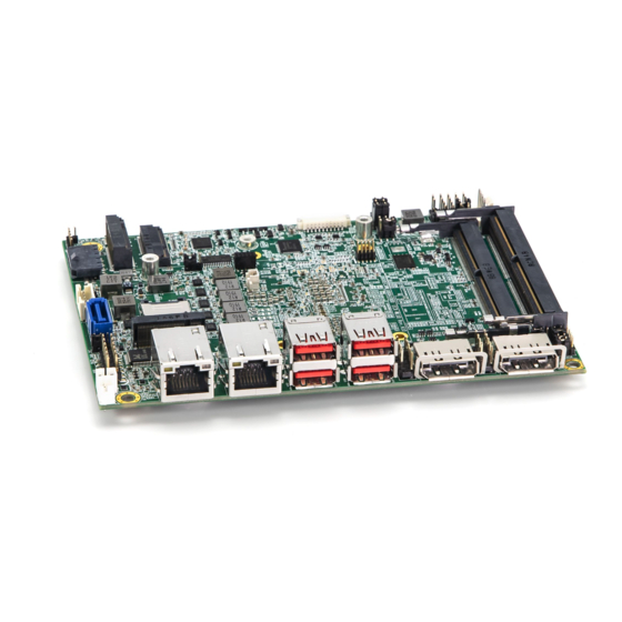
- Page 8 USB 3.1 Port 1, 2 Type A Connector CN15 USB 3.1 Port 3, 4 Type A Connector CN18 DP++ Port 2 Connector CN19 DP++ Port 1 Connector Kontron 3.5"-SBC-WLU - Quick Installation Guide - Version 2 - P/N: 0D20ECXWLU020000 // 8...
Need help?
Do you have a question about the 3.5"-SBC-WLU and is the answer not in the manual?
Questions and answers