Table of Contents
Advertisement
Quick Links
Advertisement
Table of Contents

Subscribe to Our Youtube Channel
Related Manuals for Kontron 3.5-SBC-APL


Summary of Contents for Kontron 3.5-SBC-APL
- Page 1 USER GUIDE 3.5-SBC-APL Doc. Rev. 0.1 Preliminary Doc. ID: 1061-0789...
- Page 2 User Guide 3.5-SBC-APL – Rev. 0.1 This page has been intentionally left blank www.kontron.com // 2...
- Page 3 In cases of doubt, please contact Kontron. This user guide is protected by copyright. All rights are reserved by Kontron. No part of this document may be reproduced, transmitted, transcribed, stored in a retrieval system, or translated into any language or computer language, in any form or by any means (electronic, mechanical, photocopying, recording, or otherwise), without the express written permission of Kontron.
- Page 4 ENVIRONMENTAL DAMAGE (COLLECTIVELY, "HIGH RISK APPLICATIONS"). You understand and agree that your use of Kontron devices as a component in High Risk Applications is entirely at your risk. To minimize the risks associated with your products and applications, you should provide adequate design and operating safeguards.
-
Page 5: Revision History
If you have any difficulties using this user guide, discover an error, or just want to provide some feedback, contact Kontron support. Detail any errors you find. We will correct the errors or problems as soon as possible and post the... -
Page 6: Symbols
User Guide 3.5-SBC-APL – Rev. 0.1 Symbols The following symbols may be used in this user guide DANGER indicates a hazardous situation which, if not avoided, will result in death or serious injury. WARNING indicates a hazardous situation which, if not avoided, could result in death or serious injury. -
Page 7: For Your Safety
Therefore, in the interest of your own safety and of the correct operation of your new Kontron product, you are requested to conform with the following guidelines. -
Page 8: General Instructions On Usage
General Instructions on Usage In order to maintain Kontron’s product warranty, this product must not be altered or modified in any way. Changes or modifications to the product, that are not explicitly approved by Kontron and described in this user guide or received from Kontron’s Technical Support as a special handling instruction, will void your warranty. - Page 9 User Guide 3.5-SBC-APL – Rev. 0.1 Table of Contents Symbols ..........................................6 For Your Safety ........................................7 High Voltage Safety Instructions .................................. 7 Special Handling and Unpacking Instruction ............................7 General Instructions on Usage..................................8 Environmental Protection Statement ................................ 8 Table of Contents .......................................
- Page 10 Table 14: List of Acronyms ................................... 47 List of Figures Figure 1: System Block Diagram................................... 18 Figure 2: 3.5-SBC-APL with CPU Cooler ..............................19 Figure 3: Top Side View ....................................22 Figure 4: I/O Connector Panel View ................................23 Figure 5: Rear Side Board View ................................... 24 Figure 6: Dual stack USB 3.0 Connector ..............................
-
Page 11: Introduction
1/ Introduction This user guide describes the 3.5-SBC-APL motherboard from Kontron named as 3.5-SBC-APL within this user guide. The 3.5-SBC-APL is a 3.5” form factor, single board computer based on the Intel® Apollo Lake processor and features: Intel® Atom™ Mobile processor family with (2 MB Cache, from 2 GHz to 1.8 GHz), Apollo SoC (System-on-Chip) ... -
Page 12: Installation Procedures
• Handle the board only by the edges To get the board running follow the steps listed below. If the board shipped by KONTRON already has components such as a RAM and CPU cooler mounted, then skip the relevant step(s). -
Page 13: Chassis Safety Standards
>7 mm. Do not use washers with teeth, as they can damage the PCB and cause short circuits. 2.2. Chassis Safety Standards Take care when designing chassis interface connectors in order to fulfil the IEC60950-1 standard. 3.5-SBC-APL users must evaluate the end product to ensure compliance the requirements of the IEC60950-1 safety standard are met: ... -
Page 14: Product Variants
3.5-SBC-APL – Rev. 0.1 3/ Product Variants The 3.5-SBC-APL family of multicore SoC mobile processors is available in the following processor variants at the standard operating temperature and industrial temperature. Table 1: Standard operating temperature (0°C to +60°C) Product Number... -
Page 15: Product Specification
3.5-SBC-APL – Rev. 0.1 4/ Product Specification 4.1. Component Data The table below summarizes the features of the 3.5-SBC-APL embedded motherboard. Table 3: Component Data Form Factor 102 mm x 146 mm (3.5“) Processor Intel ® Atom ™ x7 E3950 4C 2.0 GHz, 12 W Intel ®... - Page 16 3.5-SBC-APL – Rev. 0.1 1x fan pulse control Front Panel Power button, Reset button Power LED and Storage LED GPIO 1 x 18 dig I/O Kontron EC GPIO Audio 1 x audio, 1x buzzer External I/O 2x 10/100/1000 Mbit Ethernet 2x USB 3.0...
-
Page 17: Standards And Certificates
3.5-SBC-APL – Rev. 0.1 4.2. Standards and Certificates The 3.5-SBC-APL plans to be compliant to the following environmental conditions, and standards and certifications. It is the customer’s responsibility to provide sufficient airflow around each of the components to keep them within allowed temperature range. -
Page 18: Block Diagram
3.5-SBC-APL – Rev. 0.1 4.3. Block Diagram The following block diagram displays the system architecture of the 3.5-SBC-APL. Figure 1: System Block Diagram www.kontron.com // 18... -
Page 19: Supported Processors
3.5-SBC-APL – Rev. 0.1 4.4. Supported Processors The 3.5-SBC-APL supports the Atom processor family of multicore SoC mobile and the mobile version of the Intel Mobile Celeron N3350 2C. Intel® 64 Bit Architecture Intel® Virtualization Technology (VT-x) and Intel® directed I/O Virtualization Technology (VT-d) ... -
Page 20: System Memory Support
ATX power supplies that require a minimum load to stay in regulation. The 3.5-SBC-APL is powered by either a single 12 V DC Power Supply or optionally through an internal ATX 4-pin power connector using a standard ATX power supply. -
Page 21: Table 7: Supply Voltage Requirements
3.5-SBC-APL – Rev. 0.1 Table 7: Supply Voltage Requirements Supply Min. Max. Note +12 V 11.4 V 12.6 V Supply voltage should be ±5% for compliance with the ATX specification Power Supply GND www.kontron.com // 21... -
Page 22: Mainboard Views
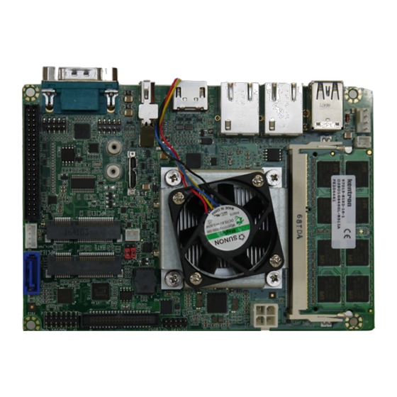
3.5-SBC-APL – Rev. 0.1 5/ Mainboard views 5.1. Top Side Figure 3: Top Side View CPU with cooler Memory Buzzer connector CPU fan connector Power connector Front panel LVDS CMOS Jumper Battery connector 10 Audio 11 SATA 12 SATA Power 13 MPCIe 14 USB 3.0 Micro B connector... -
Page 23: External I/O Connector Side
3.5-SBC-APL – Rev. 0.1 5.2. External I/O Connector Side Figure 4: I/O Connector Panel View 17 USB 3.0 connector 18 LAN connector 19 HDMI 20 Display Port 21 COM1 interface www.kontron.com // 23... -
Page 24: Rear Side
3.5-SBC-APL – Rev. 0.1 5.3. Rear Side Figure 5: Rear Side Board View www.kontron.com // 24... -
Page 25: I/O Connectors
3.5-SBC-APL – Rev. 0.1 6/ I/O Connectors 6.1. USB Connectors USB 3.0 ports are available via a dual USB connector. USB3.0 ports are backward compatible with USB2.0 Figure 6: Dual stack USB 3.0 Connector Pin Assignment USB Connector Signal VBUS1... -
Page 26: Ethernet Connectors
3.5-SBC-APL – Rev. 0.1 6.2. Ethernet Connectors The Ethernet LAN connectors (LAN1 and LAN2) provide two Ethernet ports with 10/100/1000 Mbit Ethernet data transfer rates. MDI means Media Dependent Interface. Figure 7: Ethernet LAN Connector (RJ45 Female) 8 7 6 5 4 3 2 1... -
Page 27: Display Port Connector
3.5-SBC-APL – Rev. 0.1 Pin Assignment Serial Connector Signal NDCDA NSINA NSOUTA NDTRA NDSRA NRTSA NCTSA NRIA 6.4. Display Port Connector The Display Port (DP) connector complies to the Display Port 1.2 standard. Figure 9: Display Port Connector Signal Signal... -
Page 28: Hdmi Connector
3.5-SBC-APL – Rev. 0.1 6.5. HDMI Connector Figure 10: HDMI Graphics Connector Signal Signal DVITX2+ DVITX2- DVITX1+ DVITX1- DVITX0+ DVITX0- DVITXC+ DVITXC- HDMIxCLK HDMIxDAT HPD_IN www.kontron.com // 28... -
Page 29: Internal Connectors
3.5-SBC-APL – Rev. 0.1 7/ Internal Connectors 7.1. USB Connectors The following internal USB ports are available: 2x USB 2.0 on the front panel internal header (USB1) 1x micro USB 3.0, type B in the internal header ... - Page 30 3.5-SBC-APL – Rev. 0.1 Signal Type Note +5 V Max. 0.5 A LCDVCC Max. 0.5 A LCDVCC Max. 0.5 A DDC CLK 4.7 KΩ, 3.3 V DDC DATA 4.7 KΩ, 3.3 V BKLTCTL 3.3 V level VDD ENABLE 3.3 V level BKLTEN# 3.3 V level...
-
Page 31: Sata Connector (Sata)
3.5-SBC-APL – Rev. 0.1 7.3. Internal Serial Port (COM2) The serial port connector COM2 supports one internal serial interface compliant with the RS232 standard. Figure 13: Serial Port Connector (COM2) Pin Assignment Serial Port Connector Signal Signal NDCDB NDSRB NSINB... -
Page 32: Sata Internal Power(Sata_Pwr1)
3.5-SBC-APL – Rev. 0.1 7.5. SATA Internal Power(SATA_PWR1) The SATA power connector (SATA_PWR1) supplies the SATA hard disk with either 12 V or 5 V. Figure 15: SATA Power Internal Connector Pin Assignment SATA Power (SATA_PWR) Signal +12V VCC5 7.6. -
Page 33: Buzzer Connector (Bz1)
3.5-SBC-APL – Rev. 0.1 7.7. Buzzer Connector (BZ1) The buzzer connector (BZ1) provides an audio buzzer output signal. Figure 17: Buzzer connector (BZ1) Pin assignment Buzzer Connector (BZ1) Signal VCC5 SB_HDA_SPKR 7.8. Front Panel (FP1) The front panel connector supplies signals for the power button, power LED and storage LED. -
Page 34: Power Connector (J1)
3.5-SBC-APL – Rev. 0.1 Pin Assignment System Fan Connector (SYS_FAN1) Signal SYS_FAN_CTRL SYS_FAN_TACH +12V 7.10. Power Connector (J1) The ATX 4-pin internal power supply connector is a standard motherboard power connector providing +12 V DC to the processor voltage regulator. -
Page 35: Cmos Internal (Cmos1/2)
3.5-SBC-APL – Rev. 0.1 Signal Signal WAKE# +3.3V_S5 N.C. N.C. +1.5V_S0 CLKREQ# UIM-PWR UIM-DATA PCIe_REFCLK- UIM-CLK PCIe_REFCLK+ UIM-RST UIM-VPP UIM-C8 UIM-C4 W_DISABLE# PLTRST# PCIe_RX- +3.3V_S5 PCIe_RX+ +1.5V_S0 PU 3.3V(S5) (Optional: SMB_CLK) PCIe_TX- PU 3.3V(S5) (Optional: SMB_DAT) PCIe_TX+ USB_D- USB_D+ +3.3V_S5 +3.3V_S5... - Page 36 3.5-SBC-APL – Rev. 0.1 Description 3V_BATT RTCRST# Function: Pin 1-2: Default Pin 2-3: Clear CMOS www.kontron.com // 36...
-
Page 37: Bios Settings
3.5-SBC-APL – Rev. 0.1 8/ BIOS Settings 8.1. Setup Menus The Setup utility features for menus listed in the selection bar at the top of the screen: Main Advanced Chipset Security Boot Save & Exit The Setup menus are selected via the left and right arrow keys. - Page 38 3.5-SBC-APL – Rev. 0.1 Sub-Screen Function Description Pending Operation Schedule an Operation for the Security Device Platform Hierarchy Enable/Disable Platform Hierarchy Storage Hierarchy Enable/Disable Storage Hierarchy Endorsement Hierarchy Enable/Disable Endorsement Hierarchy TPM2.0 UEFI Spec Version Select the TCG2 Spec Version Support,...
- Page 39 3.5-SBC-APL – Rev. 0.1 Sub-Screen Function Description Serial Port Legacy Console Legacy Serial Redirection Select a COM port to display redirection Redirection Settings Port Console of Legacy OS and Legacy OPROM Redirection Messages Console Redirection Enable/Disable Console Redirection Console Redirection...
- Page 40 3.5-SBC-APL – Rev. 0.1 Sub-Screen Function Description command time-out Device power-up delay Maximum time for the device will take before it properly report itself to the Host Controller Platform fTPM Enable/Disable fTPM Trust Technology Security TXE HMRFPO Enable/Disable TXE HMRFPO...
- Page 41 3.5-SBC-APL – Rev. 0.1 Sub-Screen Function Description System Fan Speed Display System Fan Speed Fan Cruise Control Disable = Full speed Thermal = does regulate fan speed according to specified temperature Speed = does regulate according to specified speed Hardware Watchdog Function 0 = Disable.
-
Page 42: Chipset Setup Menu
3.5-SBC-APL – Rev. 0.1 8.4. Chipset Setup Menu The Chipset Setup menu provides information about the configuration. Table 10: Chipset Setup Menu Functions Sub-Screen Function Description North Bridge Max Top of Low Usable DRAM (Dynamic Random Access Memory) Maximum value of TOLUD... - Page 43 3.5-SBC-APL – Rev. 0.1 Sub-Screen Function Description Internal Graphics Device DVMT Total Gfx Mem Select DVMT 5.0 Total Graphics Memory size used by the Internal Graphics Device Cd Clock Frequency Select the highest Cd Clock frequency supported by the platform...
- Page 44 3.5-SBC-APL – Rev. 0.1 Sub-Screen Function Description SCC Configuration SCC eMMC Support Enable/Disable SCC eMMC Support eMMC Max Speed Select the eMMC max Speed allowed USB Configuration XHCI Pre-Boot Driver Enable/Disable XHCI Pre- Boot Driver support USB VBUS VBUS should be ON in HOZST mode.
-
Page 45: Security Setup Menu
3.5-SBC-APL – Rev. 0.1 Sub-Screen Function Description When Disabled, the host control is not enabling DCI feature. GPIO Lock Enable to set GPIO Pad Configuration Lock for security. 8.5. Security Setup Menu The Security Setup menu provides information about the passwords and functions for specifying the security settings. -
Page 46: Save & Exit Setup Menu
3.5-SBC-APL – Rev. 0.1 Function Description time during boot. SATA Support Select Last Boot HDD only or All Sata Devices VGA Support If Auto, only install Legacy OpRom with Legacy OS and logo would NOT be shown during post. Efi driver will still be installed with EFI OS. -
Page 47: Appendix: List Of Acronyms
3.5-SBC-APL – Rev. 0.1 APPENDIX: LIST OF ACRONYMS Table 14: List of Acronyms Base Management Controller Command-Line Interface Computer-on-Module Error Checking and Correction Federal Communication Commission Field Replaceable Unit GPIO General Purpose Input Output Graphics Processing Unit HDAC High Definition Audio Codec... - Page 48 Kontron is a listed company. Its shares are traded in the Prime Standard segment of the Frankfurt Stock Exchange and on other exchanges under the symbol “KBC”. For more information, please visit: http://www.kontron.com/...
Need help?
Do you have a question about the 3.5-SBC-APL and is the answer not in the manual?
Questions and answers