Table of Contents
Advertisement
Quick Links
Advertisement
Table of Contents

Related Manuals for Sungrow SH3K6-30


Summary of Contents for Sungrow SH3K6-30
-
Page 3: All Rights Reserved
It is prohibited to use data contained in firmware or software developed by • SUNGROW, in part or in full, for commercial purposes by any means. It is prohibited to perform reverse engineering, cracking, or any other operations that •... -
Page 4: About This Manual
. . s s u u n n g g r r o o w w p p o o w w e e r r . . c c o o m m or on the webpage of the respective component manufacturer. V V a a l l i i d d i i t t y y This manual is valid for the following inverter models: SH3K6-30 • SH4K6-30 • SH5K-30 •... - Page 5 S S y y m m b b o o l l E E x x p p l l a a n n a a t t i i o o n n Indicates a situation that, if not avoided, could result in equipment or property damage.
-
Page 7: Table Of Contents
C C o o n n t t e e n n t t s s All Rights Reserved .....................I About This Manual .....................II 1 Safety ......................1 1.1 PV Panels..................... 1 1.2 Utility Grid ....................1 1.3 Inverter ......................2 1.4 Battery ...................... - Page 8 3.3.2 Discharge Management ..............24 3.3.3 Maintenance Management............... 24 3.4 Communication and Configuration ............. 24 4 Unpacking and Storage ................25 4.1 Unpacking and Inspection ................25 4.2 Identifying the Inverter ................25 4.3 Scope of Delivery ..................26 4.4 Inverter Storage ..................28 5 Mechanical Mounting ................
- Page 9 6.7.2 WLAN Connection ................51 6.7.3 RS485 Connection ................51 6.8 Smart Energy Meter Connection..............53 6.9 Battery Connection..................56 6.9.1 Connecting the Power Cable............. 56 6.9.2 Connecting the CAN Cable ............... 58 6.10 Emergency Load Connection (Backup) ............ 59 6.11 DO Connection..................
- Page 10 9.1.2 Troubleshooting of the Errors ............84 9.2 Maintenance ....................97 9.2.1 Maintenance ..................98 9.2.2 Replacing the Button Battery............. 98 10 Appendix I I : : LCD Operation ..............100 10.1 Main Screen................... 100 10.2 LCD Menu....................101 10.3 Starting and Stopping the Inverter ............103 10.4 Advanced Settings .................
- Page 11 11.3.2 For Countries except "IT" and "TH"..........122 11.4 "Q(U)" Mode ..................123 11.4.1 For Countries "IT" and "TH" ............123 11.4.2 For Countries except "IT" and "TH"..........124 12 Appendix III: Active Power Response ..........127 12.1 Volt-watt Response ................127 12.1.1 For the Country "IT"...
-
Page 13: Safety
The safety instructions in this manual cannot cover all the precautions that should be followed. Perform operations considering actual onsite conditions. SUNGROW shall not be held liable for any damage caused by violation of the safety instructions in this manual. -
Page 14: Inverter
1 Safety User Manual All electrical connections must be in accordance with local and national standards. Only with the permission of the local utility grid company, the inverter can be connected to the utility grid. 1.3 Inverter Danger to life from electric shocks due to live voltage Do not open the enclosure when the inverter is running. -
Page 15: Battery
User Manual 1 Safety Only qualified personnel can perform the country setting. Unauthorized alteration may cause a breach of the type-certificate marking. Risk of inverter damage due to electrostatic discharge (ESD)! By touching the electronic components, you may damage the inverter. For inverter handling, be sure to: avoid any unnecessary touching;... -
Page 16: Skills Of Qualified Personnel
1 Safety User Manual Provide sufficient ventilation for the battery system to prevent flames and sparks from the explosive hydrogen gas that the batteries release. Due to the dangers of hydrogen gas and battery electrolyte: locate batteries in a designated area, complying with the local regulations; •... -
Page 17: System Solution
N N o o m m i i n n a a l l G G r r i i d d V V o o l l t t a a g g e e M M o o d d e e l l SH3K6-30 3680 W... -
Page 18: Dimensions
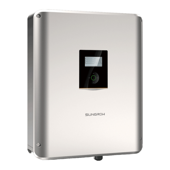
2 System Solution User Manual F F i i g g u u r r e e 2 2 - - 1 1 Inverter Appearance *The image shown here is for reference only. The actual product you receive may differ. D D e e s s c c r r i i p p t t i i o o n n N N o o . -
Page 19: Lcd Panel
User Manual 2 System Solution F F i i g g u u r r e e 2 2 - - 2 2 Dimensions (unit: mm) *The image shown here is for reference only. The actual product you receive may differ. 2.1.4 LCD Panel The LCD panel with an indicator and four buttons is on the front of the inverter. -
Page 20: Pv Energy Storage System (Pv Ess)
R R e e m m a a r r k k s s Compatible with monocrystalline silicon, PV strings polycrystalline silicon, and thin-film without grounding. Inverter SH3K6-30 / SH4K6-30 / SH5K-30. Smart Energy Meter Measures the feed-in power and communicates (single-phase for with the inverter via the RS485 port. example) Utility grid Grid grounding system types: TT, TN. - Page 21 D D e e c c l l a a r r a a t t i i o o n n F F o o r r B B a a c c k k - - U U p p F F u u n n c c t t i i o o n n The following statement involves SUNGROW general policies about the hybrid inverters described in this manual.
- Page 22 2 System Solution User Manual Moreover, inverter will draw power from the mains if the power from the PV and • battery is less than the load power. E E n n e e r r g g y y M M a a n n a a g g e e m m e e n n t t d d u u r r i i n n g g N N i i g g h h t t The battery discharges to provide energy to loads.
-
Page 23: Retrofitting The Existing Pv System
User Manual 2 System Solution If the Smart Energy Meter is abnormal or not equipped, the inverter will run normally, however, the battery can be charged but not allowed to discharge. In this case the feed- in power setting will be ineffective, and the DO function for optimized mode will be disabled. - Page 24 2 System Solution User Manual The existing PV inverter provides power to the PV ESS, as the power flow shown on the main screen. Refer to "7.4.2 Adding the Existing Inverter" to set the rated power of the existing PV inverter.
-
Page 25: Function Description
Function Description 3.1 Safety Function 3.1.1 Protection Several protective functions are integrated in the inverter, including short circuit protection, grounding insulation resistance surveillance, residual current protection, anti- islanding protection, DC overvoltage/overcurrent protection, etc. 3.1.2 Earth Fault Alarm The inverter has integrated a multiple-function dry-contact (DO relay), which can be used for the external alarm for earth fault. -
Page 26: Power Derating
3 Function Description User Manual 3.2.1 Power Derating Power derating is a way to protect the inverter from overload or potential faults. In addition, the derating function can also be activated following the requirements of the utility grid. Situations requiring inverter power derating are: grid dispatching •... -
Page 27: Drm ("Au"/"Nz")
User Manual 3 Function Description F F e e e e d d - - i i n n P P o o w w e e r r L L i i m m i i t t D D e e r r a a t t i i n n g g When the Smart Energy Meter detects that the feed-in power is greater than the limit value on the LCD, the inverter will reduce the output power within the specified range. -
Page 28: Regular Operational Voltage Range
3 Function Description User Manual The DRED may assert more than one DRM at a time. The following shows the priority order in response to multiple DRMs. M M u u l l t t i i p p l l e e M M o o d d e e s s P P r r i i o o r r i i t t y y O O r r d d e e r r DRM1…DRM4 DRM1 >... - Page 29 User Manual 3 Function Description P P a a r r a a m m e e t t e e r r D D e e s s c c r r i i p p t t i i o o n n Overvoltage protection value.
-
Page 30: Regular Operational Frequency Range
3 Function Description User Manual * The maximum time to disconnect refers to the interval between the abnormal voltage level and the action of inverter (disconnect from the grid). When the voltage level is out of the operational levels shown in the table, the inverter will disconnect from the grid. - Page 31 User Manual 3 Function Description P P a a r r a a m m e e t t e e r r D D e e s s c c r r i i p p t t i i o o n n Overfrequency protection value.
-
Page 32: Reactive Power Regulation
3 Function Description User Manual Table 3-7 Disconnection related to Frequency G G r r i i d d F F r r e e q q u u e e n n c c y y L L e e v v e e l l M M a a x x i i m m u u m m T T i i m m e e t t o o D D i i s s c c o o n n n n e e c c t t ( ( 1 1 ) ) f <... -
Page 33: Load Control
3.3 Battery Management The following kinds of batteries are compatible with the PV ESS. Further battery models will be made compatible in the furture. Li-ion battery from SUNGROW, LG Chem, GCL, Pylon, BYD and TAWAKI. • Lead-acid batteries which require manual configuration. -
Page 34: Charge Management
Other lead-acid < 30 V Configured by the customer * The SOC limits of Li-ion batteries except SUNGROW batteries can be modified via iSolarCloud App or the iSolarCloud server by qualified personnel. 3.3.1 Charge Management A hybrid inverter should provide a means for temperature compensation of the battery charge voltages. - Page 35 • The emergency charge command reported to the inverter is cleared. • (only for SUNGROW and BYD batteries) Table 3-10 Default SOC Conditions for Li-ion Battery Emergency Charge S S t t a a t t u u s s...
-
Page 36: Discharge Management
3 Function Description User Manual the maximum/recommended charge current from the battery manufacturer. • For this reason, the battery charge current value may not reach the nominal power. If the PV voltage is higher than the upper limit value of MPP voltage (560 V), •... -
Page 37: Unpacking And Storage
Check the inner contents for damage after unpacking. • Contact SUNGROW or the supplier in case of any damage or incompleteness. Do not dispose of the original packing case. It is recommended to store the inverter in it. 4.2 Identifying the Inverter The nameplate can be found on both the inverter and the packing case. -
Page 38: Scope Of Delivery
D D e e s s c c r r i i p p t t i i o o n n I I t t e e m m SUNGROW logo and product type Technical data of inverter Instructions and marks of conformity... - Page 39 User Manual 4 Unpacking and Storage F F i i g g u u r r e e 4 4 - - 2 2 Scope of Delivery Q Q u u a a n n - - D D e e s s c c r r i i p p t t i i o o n n I I t t e e m m N N a a m m e e t t i i t t y y...
-
Page 40: Inverter Storage
4 Unpacking and Storage User Manual Q Q u u a a n n - - D D e e s s c c r r i i p p t t i i o o n n I I t t e e m m N N a a m m e e t t i i t t y y Used to fasten wall-mounting bracket onto... - Page 41 User Manual 4 Unpacking and Storage Store the inverter in the original packing case with the desiccant inside. • The storage temperature must be always between -30° C and +70° C, and the • storage relative humidity must be always between 0 and 95 %, non-condensing. In case of stacking storage, the number of stacking layers should never exceed the •...
-
Page 42: Mechanical Mounting
Mechanical Mounting 5.1 Safety during Mounting Make sure there is no electrical connection before installation. In order to avoid electric shock or other injury, make sure that holes will not be drilled over any electricity or plumbing installations. Risk of injury due to improper handling Always follow the instructions when moving and positioning the inverter. -
Page 43: Carrier Requirements
User Manual 5 Mechanical Mounting The ambient temperature and relative humidity must meet the following • requirements. Avoid direct exposure to sun, rain and snow. • The inverter should be well ventilated. Ensure air circulation. • Never install the inverter in living areas. The inverter will generate noise during •... -
Page 44: Installation Tools
5 Mechanical Mounting User Manual 5.3 Installation Tools Installation tools include but are not limited to the following recommended ones. If necessary, use other auxiliary tools on site. Table 5-1 Tool specification S S p p e e c c i i f f i i c c a a t t i i o o n n N N o o . -
Page 45: Moving The Inverter
User Manual 5 Mechanical Mounting S S p p e e c c i i f f i i c c a a t t i i o o n n N N o o . . Crimp range: 4 mm –6 mm Range: ≥... - Page 46 5 Mechanical Mounting User Manual Step 2 Mount the inverter to the bracket. Step 3 Secure the inverter with two M5 screws and washers. (3.0 N.m) - - - - E E n n d d...
-
Page 47: Electrical Connection
Electrical Connection 6.1 Safety Instructions Prior to any electrical connections, keep in mind that the inverter has dual power supplies. It is mandatory for the qualified personnel to wear personal protective equipments (PPE) during the electrical work. Danger to life due to a high voltage inside the inverter! The PV string will generate lethal high voltage when exposed to sunlight. -
Page 48: Terminal Description
6 Electrical Connection User Manual 6.2 Terminal Description Terminals located at the bottom of the inverter are shown below. F F i i g g u u r r e e 6 6 - - 1 1 Terminals at the Bottom of the Inverter D D e e c c i i s s i i v v e e D D e e s s c c r r i i p p t t i i o o n n N N o o . - Page 49 User Manual 6 Electrical Connection Connection terminals on the inner configuration circuit board are shown below. F F i i g g u u r r e e 6 6 - - 2 2 Configuration Circuit Board Inside the Inverter D D e e c c i i s s i i v v e e D D e e s s c c r r i i p p t t i i o o n n N N o o .
-
Page 50: Electrical Connection Overview
6 Electrical Connection User Manual D D e e c c i i s s i i v v e e D D e e s s c c r r i i p p t t i i o o n n N N o o . -
Page 51: Additional Grounding Connection
User Manual 6 Electrical Connection Table 6-1 Cable Requirements N N - - C C a a b b l l e e C C r r o o s s s s - - T T y y p p e e C C a a b b l l e e o o . -
Page 52: Additional Grounding Requirements
6 Electrical Connection User Manual 6.4.1 Additional Grounding Requirements All non-current carrying metal parts and device enclosures in the PV power system should be grounded, for example, brackets of PV modules and inverter enclosure. The additional grounding terminal is equipped at the side of the inverter. Be sure to connect this additional grounding terminal to the PE bar for reliable grounding and ensure that the grounding resistance should be less than 10 Ohm. -
Page 53: Ac Cable Connection
R R e e c c o o m m m m e e n n d d e e d d S S p p e e c c i i f f i i c c a a t t i i o o n n I I n n v v e e r r t t e e r r M M o o d d e e l l SH3K6-30 40 A... - Page 54 6 Electrical Connection User Manual Step 3 Remove the cable jacket by 40 mm, and strip the wire insulation by 8-15 mm. Step 4 Fully insert the conductors to the corresponding terminal and tighten the screws with the torque 0.8 N.m. Pull cables outward to check whether they are firmly installed. Observe the terminal layout of terminal block.
-
Page 55: Installing The Ac Connector
User Manual 6 Electrical Connection - - - - E E n n d d 6.5.3 Installing the AC Connector High voltage may be present in the inverter! Ensure all cables are voltage-free before electrical connection. Do not connect the AC circuit breaker until all inverter electrical connections are completed. -
Page 56: Dc Cable Connection
6 Electrical Connection User Manual 6.6 DC Cable Connection Danger of electric shock! The PV array will generate lethal high voltage once exposed to sunlight. Make sure the PV array is well insulated to ground before connecting it to the inverter. -
Page 57: Dc Side Requirements
PV input cables are of the same type. 6.6.2 DC Side Requirements SUNGROW provides corresponding PV connectors in the scope of delivery for quick connection of PV inputs. To ensure IP65 protection, use only the supplied connector or the connector... -
Page 58: Assembling The Pv Connectors
6 Electrical Connection User Manual 6.6.3 Assembling the PV Connectors High voltage may be present in the inverter! Ensure all cables are voltage-free before performing electrical operations. • Do not connect the AC circuit breaker before finishing electrical connection. • Use the MC4 terminals within the scope of delivery. -
Page 59: Installing The Pv Connectors
User Manual 6 Electrical Connection - - - - E E n n d d 6.6.4 Installing the PV Connectors Step 1 Rotate the DC switch to "OFF" position. Step 2 Check the cable connection of the PV string for polarity correctness and ensure that the open circuit voltage in any case does not exceed the inverter input limit of 600 V. -
Page 60: Communication Connection
Arc or contactor overtemperature may occur if the PV connectors are not • firmly in place, and SUNGROW shall not be held liable for any damage caused due to this operation. Step 4 Seal the unused PV terminals with the terminal caps. -
Page 61: Ethernet Connection
User Manual 6 Electrical Connection 6.7.1 Ethernet Connection The following figure shows how the Ethernet connection may work with a router. F F i i g g u u r r e e 6 6 - - 4 4 Ethernet Connection with a Router C C a a b b l l e e w w i i t t h h o o u u t t R R J J 4 4 5 5 p p l l u u g g Unscrew the swivel nut from any C C o o m m . - Page 62 6 Electrical Connection User Manual Install the RJ45 plug to the E E t t h h e e r r n n e e t t port. Fasten the swivel nut with a torque of 4–5 N.m and connect the other end to the socket of the switch or the router.
-
Page 63: Wlan Connection
User Manual 6 Electrical Connection Install the RJ45 plug to the E E t t h h e e r r n n e e t t port. Fasten the swivel nut with a torque of 4–5 N.m and connect the other end to the socket of the switch or the router. - Page 64 6 Electrical Connection User Manual Step 2 Lead the cable through the cable gland. Step 3 Remove the cable jacket and strip the wire insulation. Step 4 Plug the wires into the corresponding terminals according the marks without tool tightening. For reconnection, press the part as shown in the red circle so as to pull out the cable.
-
Page 65: Smart Energy Meter Connection
The Smart Energy Meter should be installed next to the main switch. This section mainly describes the cable connections on the inverter side. Refer to the quick guide delivered with the SUNGROW meter for the connections on the meter side. For the single-phase meter, with the signal from the 1-phase sensor, the inverter determines the energy exchange with the utility grid on one phase. - Page 66 6 Electrical Connection User Manual * The MEN connection only applies to Australia and New Zealand. Step 1 Take out the RS485 cable (terminal marks A A 2 2 and B B 2 2 ) from the packaging. Step 2 Unscrew the swivel nut from any C C o o m m . . port. Step 3 Lead the cable through the cable gland.
- Page 67 User Manual 6 Electrical Connection Step 4 Plug the wires into terminals A A 2 2 and B B 2 2 on the inverter without tool tightening. For reconnection, press the part as shown in the red circle so as to pull out the cable.
-
Page 68: Battery Connection
6 Electrical Connection User Manual 6.9 Battery Connection This section mainly describes the cable connections on the inverter side. Refer to the instructions supplied by the battery manufacturer for the connections on the battery side. Only use properly insulated tools to prevent accidental electric shock or short •... - Page 69 User Manual 6 Electrical Connection Step 3 Unscrew the swivel nut from the B B A A T T + + and B B A A T T - - ports. Step 4 Lead the cable through the cable gland. Step 5 Loosen and remove the screw sets on the B B A A T T + + and B B A A T T - - terminal blocks.
-
Page 70: Connecting The Can Cable
The CAN cable enables the communication between the inverter and the Li-ion battery from LG, Sungrow, GCL, Pylon (US2000B), BYD or TAWAKI. Step 1 Take out the CAN cable (terminal marks C C A A N N H H and C C A A N N L L ) from the packaging. -
Page 71: Emergency Load Connection (Backup)
User Manual 6 Electrical Connection Step 5 Fasten the swivel nut with a torque of 4– 5 N. m and connect the other end to the battery. - - - - E E n n d d 6.10 Emergency Load Connection (Backup) Risk of inverter damage due to incorrect cable connection. - Page 72 6 Electrical Connection User Manual Observe the terminal layout of terminal block. Avoid connecting the phase line to terminal "PE" or "N" , otherwise the inverter will not function properly and the loss of any or all the warranty rights may follow. Step 4 Assemble the housing, the terminal block and cable gland with a torque of 2–3 N.m).
-
Page 73: Do Connection
User Manual 6 Electrical Connection Step 6 Connect the other ends to the emergency loads. Pull all the lines outward to check whether they are firmly installed. - - - - E E n n d d 6.11 DO Connection The inverter has one DO relay with multiple functions as follows: Consumer load control. - Page 74 6 Electrical Connection User Manual An AC contactor must be installed between the inverter and appliances. It is • prohibited to connect the load directly to the DO port. The current of the DO dry contact should not be larger than 3 A. •...
-
Page 75: Drm/Spi Connection
User Manual 6 Electrical Connection Step 4 Plug the wires into D D O O terminals without tool tightening. For reconnection, press the part as shown in the red circle so as to pull out the cable. Step 5 Fasten the swivel nut with a torque of 4–5 N.m and connect the other end of the cable to the original edge of the AC contactor. - Page 76 6 Electrical Connection User Manual After the connection, the DRED assert DRMs by shorting together terminals as specified in the following table. The modes from DRM0 to DRM8 are supported by the inverter and the information is marked on the label located near the DRM terminals. Table 6-2 Method of Asserting DRMs A A s s s s e e r r t t e e d d b b y y S S h h o o r r t t i i n n g g T T e e r r m m i i n n a a l l s s M M o o d d e e...
-
Page 77: Spi Connection ("It")
User Manual 6 Electrical Connection Step 3 Remove the cable jacket and strip the wire insulation. Step 4 Plug the wires into the corresponding terminals without tool tightening, as shown below. For reconnection, press the part as shown in the red circle so as to pull out the cable. - Page 78 6 Electrical Connection User Manual N N O O . . I I n n t t e e r r f f a a c c e e S S P P I I F F u u n n c c t t i i o o n n Receive external signal/command to change the frequency Ethernet protection parameters or shutdown the inverter.
- Page 79 User Manual 6 Electrical Connection F F i i g g u u r r e e 6 6 - - 6 6 RS485 Connection to External Device For reconnection, press the part as shown in the red circle so as to pull out the cable.
- Page 80 6 Electrical Connection User Manual L L o o c c a a l l C C o o n n t t r r o o l l E E x x t t e e r r n n a a l l C C o o n n t t r r o o l l P P a a r r a a m m e e t t e e r r E E x x p p l l a a n n a a t t i i o o n n Maximum frequency 1 (F>) tripping time Maximum frequency 2 (F>>) (Hz)
-
Page 81: Commissioning
Commissioning 7.1 Inspection before Commissioning Check the following items before starting the inverter: All the installation sites are convenient for operation, maintenance and service. • Check and confirm that all devices are firmly installed. • Space for ventilation is sufficient for one inverter or multiple inverters. •... -
Page 82: Powering On The System
7 Commissioning User Manual F F i i g g u u r r e e 7 7 - - 1 1 Button Operations 7.3 Powering on the System If all the items mentioned in section "7.1 Inspection before Commissioning" are OK, proceed as follows to start the inverter for the first time. -
Page 83: Lcd Initial Settings
User Manual 7 Commissioning Countries except Germany ("DE") • - - - - E E n n d d 7.4 LCD Initial Settings 7.4.1 Setting the Country F F o o r r C C o o u u n n t t r r i i e e s s " " A A U U " " a a n n d d " " N N Z Z " " P P r r e e s s s s to select the grid standard and P P r r e e s s s s E E N N T T to confirm. - Page 84 7 Commissioning User Manual Table 7-3 Parameters of Grid Standards in Australia P P a a r r a a m m e e t t e e r r D D e e f f a a - - E E x x p p l l a a n n a a t t i i o o n n u u l l t t A A G G...
- Page 85 User Manual 7 Commissioning F F o o r r t t h h e e C C o o u u n n t t r r y y " " B B R R A A " " Select the grid type and set the protective parameters.
-
Page 86: Adding The Existing Inverter
7 Commissioning User Manual D D e e f f a a u u l l t t / / R R a a n n g g e e P P a a r r a a m m e e t t e e r r 2 2 2 2 0 0 V V G G r r i i d d 2 2 3 3 0 0 V V G G r r i i d d 1-Time (s) -
Page 87: Setting Feed-In Power
User Manual 7 Commissioning 7.4.3 Setting Feed-in Power O O N N : : no power could be fed into the grid. • O O F F F F : : all system output power could be fed into the grid. •... -
Page 88: Setting Reactive Power Regulation ("De")
7 Commissioning User Manual 7.4.6 Setting Reactive Power Regulation ("DE") O O F F F F : The reactive power regulation function is disabled. The power factor (PF) is limited to +1.000. P P F F : The inverter is capable of operating with fixed power factor. The PF ranges from 0.8 leading to 0.8 lagging. -
Page 89: Result Verification
F F o o r r I I n n c c o o r r r r e e c c t t I I n n s s t t a a l l l l a a t t i i o o n n P P o o s s i i t t i i o o n n Make sure that the 1-phase sensor of the Sungrow Energy Meter should be placed to the phase line (L) from the main switch. - Page 90 7 Commissioning User Manual F F i i g g u u r r e e 7 7 - - 2 2 Installation Position for Single-phase Energy Meter L L C C D D E E x x p p l l a a n n a a t t i i o o n n A A c c t t i i o o n n Turn off all the household loads.
-
Page 91: Battery Information
User Manual 7 Commissioning F F i i g g u u r r e e 7 7 - - 4 4 Correct Power cable connection for Three-phase Meter L L C C D D E E x x p p l l a a n n a a t t i i o o n n A A c c t t i i o o n n Method 1: Turn off all the household loads. -
Page 92: System Time
7 Commissioning User Manual If the battery type or capacity setting is inconsistent with the actual, the charge/ discharge current may be less than the actual charge/discharge ability. However, the system can operate normally. Please stop the inverter via the LCD menu. Reset the battery type and parameters and then start the inverter again. -
Page 93: System Decommissioning
System Decommissioning 8.1 Decommissioning the Inverter Please strictly follow the following procedure. Otherwise it will cause lethal voltages or unrecoverable damage to the inverter. 8.1.1 Disconnecting the Inverter For maintenance or other service work, the inverter must be switched off. Proceed as follows to disconnect the inverter from the AC and DC power sources. -
Page 94: Dismantling The Inverter
8.2 Decommissioning the Battery Decommission the battery in the system after the inverter is decommissioned, following the steps for a Li-ion battery or lead-acid battery below. SUNGROW is not liable for disposal of the battery. D D e e c c o o m m m m i i s s s s i i o o n n i i n n g g L L i i - - i i o o n n B B a a t t t t e e r r y y Disconnect the DC circuit breaker between the battery and the inverter. - Page 95 User Manual 8 System Decommissioning If the battery port voltage is zero, disconnect the power cables between the battery and the inverter. D D e e c c o o m m m m i i s s s s i i o o n n i i n n g g L L e e a a d d - - a a c c i i d d B B a a t t t t e e r r y y Disconnect the DC switch between the battery and the inverter.
-
Page 96: Troubleshooting And Maintenance
The LED indicator goes out. Check whether the DC input voltage exceeds the start voltage of the inverter. If all of the above are OK, please contact SUNGROW. A fault is not resolved. Perform troubleshooting according to the fault type screen. - Page 97 App or the LCD. 3. Check whether the cross-sectional area of the AC cable meets the requirement. 4. If the error persists, contact SUNGROW. Grid transient overvoltage (on-grid mode). 1. Generally, the inverter will be reconnected to the grid after the grid recovers.
- Page 98 App or the LCD. of the inverter. (stage I) 3. If the error persists, contact SUNGROW. Generally, the inverter will be reconnected to the grid after the grid recovers. If the fault occurs repeatedly: 1.
- Page 99 2. Check whether the grid is operating The average grid voltage normally. in 10 minutes exceeds 3. If the error persists, contact SUNGROW. the upper limit. Generally, the inverter will be reconnected to the grid after the grid recovers. If the fault occurs repeatedly: 1.
- Page 100 2. Check and clean the heat sink. of the safe range. 3. If the error persists, contact SUNGROW. 2. Wait 5 minutes for the inverter to recover or Relay fault on the grid restart the system.
- Page 101 1. Wait 5 minutes for the inverter to recover or INV undervoltage fault in restart the system. the off-grid mode. 2. If the error persists, contact SUNGROW. The version of CPLD (- complex programmable Power off the system and program the CPLD.
- Page 102 App or the LCD. value, which is lower than the protective value of 3. If the error persists, contact SUNGROW. error 009. (stage II) The inverter is not 1. Check whether there is a reliable grounding grounded.
- Page 103 3. Restart the system. Bypass relay fault. 1. Wait 5 minutes for the inverter to recover or restart the system. Off-grid relay fault. 2. If the error persists, contact SUNGROW. Slave DSP redundant fault. Phase voltage sampling fault. DC injection sampling fault.
- Page 104 RS485_2 is pushed to "ON" when the length of RS485 cable is longer than 100 m. 1. Wait 5 minutes for the inverter to recover or Transient BDC charging restart the system. overcurrent fault. 2. If the error persists, contact SUNGROW.
- Page 105 BDC current sampling 1. Wait 5 minutes for the inverter to recover or fault. restart the system. Slave DSP communication fault. 2. If the error persists, contact SUNGROW. BDC soft-start fault. 800, 802, BDC internal permanent Restart the inverter. 804, faults.
- Page 106 9 Troubleshooting and Maintenance User Manual E E r r r r o o r r D D e e s s c c r r i i p p t t i i o o n n T T r r o o u u b b l l e e s s h h o o o o t t i i n n g g C C o o d d e e 1.
- Page 107 4. Wait a moment for system recovery or restart the system. CAN ID competing Restart the system, if the fault persists, please failure. contact SUNGROW for a solution. Mismatched software Contact SUNGROW for a solution. version. Software self-verifying Restart the system, if the error persists, please failure.
- Page 108 9 Troubleshooting and Maintenance User Manual E E r r r r o o r r D D e e s s c c r r i i p p t t i i o o n n T T r r o o u u b b l l e e s s h h o o o o t t i i n n g g C C o o d d e e 1.
-
Page 109: Maintenance
As the inverter contains no component parts that can be maintained, never arbitrarily replace any internal components. For any maintenance need, please contact SUNGROW. Otherwise, SUNGROW shall not be held liable for any damage caused. Servicing of the device in accordance with the manual should never be undertaken in the absence of proper tools, test equipments or the latest revision of the manual which has been clearly and thoroughly understood. -
Page 110: Maintenance
For any maintenance need, please contact SUNGROW. Otherwise, • SUNGROW shall not be held liable for any damage caused. I I t t e e m m M M e e t t h h o o d d... - Page 111 User Manual 9 Troubleshooting and Maintenance There is a button battery on the inner PCB board of the LCD. Contact SUNGROW for replacement when the relevant fault alarm occurs. Check the fastener, appearance, voltage, and resistance quarterly and annually.
-
Page 112: Appendix I I : : Lcd Operation
10 Appendix I I : : LCD Operation Refer to " Button Operations" for button operations when setting parameters. 10.1 Main Screen After successful commissioning, the LCD screen will enter the main screen. (1) Current PV input power (2) Current feed-in power (3) Warning information (4) Total load consumption... -
Page 113: Lcd Menu
Whether the battery level is sufficient and the cable connection is correct. • If no anomaly is found, disconnect the DC switch and the main switch to • restart. If it still does not work, contact SUNGROW. • 10.2 LCD Menu The following figure shows the LCD menu. - Page 114 10 Appendix I I : : LCD Operation User Manual F F i i g g u u r r e e 1 1 0 0 - - 1 1 LCD Menu Tree (1) The power value indicated represents the average value during the time interval. The energy yields displayed are indicative only.
-
Page 115: Starting And Stopping The Inverter
User Manual 10 Appendix I I : : LCD Operation A A b b b b r r e e v v i i a a t t i i o o n n C C o o m m p p l l e e t t e e A A b b b b r r e e v v i i a a t t i i o o n n C C o o m m p p l l e e t t e e Power... -
Page 116: Advanced Settings
B B a a t t t t e e r r y y T T y y p p e e S S O O C C T T h h r r e e s s h h o o l l d d Sungrow (retrofitting system)/ LG ≤ 6 % ≤... -
Page 117: Adding The Existing Inverter
User Manual 10 Appendix I I : : LCD Operation 10.4.3 Adding the Existing Inverter Refer to the description in "7.4.2 Adding the Existing Inverter". 10.4.4 Setting Feed-in Power Refer to the description in "7.4.3 Setting Feed-in Power". 10.4.5 Setting Battery Type Refer to "10.3 Starting and Stopping the Inverter"... -
Page 118: Setting Battery Usage Time
10 Appendix I I : : LCD Operation User Manual – The charge or discharge voltage is not beyond the upper limit (63 V / 70 V). Over Temp / Low Temp: If the battery voltage or temperature is beyond the •... -
Page 119: Setting Forced Charge
User Manual 10 Appendix I I : : LCD Operation Battery usage enabled (Weekend): 10.4.7 Setting Forced Charge In the system without a battery, a prompt will appear. P P r r e e s s s s E E N N T T to continue the setting. When there is no PV power, the import power from the grid charges the energy •... - Page 120 10 Appendix I I : : LCD Operation User Manual backup function has been enabled via the LCD menu. Otherwise the inverter will stop running with the ”Error” state displayed on the LCD main screen. For more parameter settings, please visit the iSolarCloud App or the iSolarCloud server. For the function of interface protection system (SPI) for Italy, see "6.12.2 SPI Connection...
- Page 121 User Manual 10 Appendix I I : : LCD Operation E E x x p p l l a a n n a a t t i i o o n n R R a a n n g g e e P P a a r r a a m m e e t t e e r r Not BRA: 45.00–50.00...
-
Page 122: Setting Reactive Power Regulation
10 Appendix I I : : LCD Operation User Manual Table 10-7 Default Values of Protective Parameters (3) B B R R A A T T H H P P a a r r a a m m e e t t e e r r N N Z Z S S A A 2 2 2 2 0 0 V V... - Page 123 User Manual 10 Appendix I I : : LCD Operation In this mode, set the Start time and End time, the system will control the load operation during the interval. Take 09:00 am–09:30 am as an example. F F i i g g u u r r e e 1 1 0 0 - - 2 2 DO Operation in Timer Control ON/OFF Control •...
- Page 124 10 Appendix I I : : LCD Operation User Manual During the setting interval, the DO function will be enabled to power on the load if the excess PV energy exceeds the optimized power value. – The optimized mode is disabled in an off-grid system. –...
-
Page 125: Setting The Communication Parameters
User Manual 10 Appendix I I : : LCD Operation 10.4.13 Setting the Communication Parameters E E t t h h e e r r n n e e t t The communication address ranges from 1 to 247. • The IP, sub net, gateway, DNS1 and DNS2 can be modified only when the DHCP is •... -
Page 126: Multiple Parallel Setting
10 Appendix I I : : LCD Operation User Manual Enter the "Settings" menu and navigate to "Factory Reset". P P r r e e s s s s E E N N T T to confirm. 10.4.16 Multiple Parallel Setting In a hybrid system with two inverters in parallel via an RS485 connection, enable the parallel setting. - Page 127 User Manual 10 Appendix I I : : LCD Operation C C o o u u n n t t r r y y C C o o d d e e L L a a n n g g u u a a g g e e F F u u l l l l N N a a m m e e Italy Italian...
-
Page 128: Viewing The Error Codes
10 Appendix I I : : LCD Operation User Manual E E x x p p l l a a n n a a t t i i o o n n R R a a n n g g e e P P a a r r a a m m e e t t e e r r 50.00 Hz–55.00 Grid overfrequency 2 (F>>) -
Page 129: Viewing Error Record
User Manual 10 Appendix I I : : LCD Operation 10.7.2 Viewing Error Record P P r r e e s s s s / to turn pages and view all error records. 1: the error is triggered. 0: the error is cleared. 10.8 Self-test (Italy) The inverter is integrated with interface protection functions and provides an auto test system to verify the maximum/minimum frequency and maximum/minimum voltage... - Page 130 10 Appendix I I : : LCD Operation User Manual Table 10-10 Operational Voltage Parameter Description P P a a r r a a m m e e t t e e r r E E x x p p l l a a n n a a t t i i o o n n 81>.S1 Overfrequency test (stage I) 81<.S1...
- Page 131 User Manual 10 Appendix I I : : LCD Operation P P a a s s s s . . : The inverter will restore the normally used settings and automatically reconnect to the grid. F F a a i i l l : The inverter will report the error 1 1 0 0 5 5 . The inverter cannot reconnect to the network until the test faults are cleared.
-
Page 132: Appendix Ii: Reactive Power Regulation
11 Appendix II: Reactive Power Regulation The submenu is as shown on the right. Refer to "10.2 LCD Menu" for the navigation. P P r r e e s s s s / to select the desired option and P P r r e e s s s s E E N N T T to confirm. -
Page 133: For Countries "It" And "Th
User Manual 11 Appendix II: Reactive Power Regulation 11.3.1 For Countries "IT" and "TH" The PF of the inverter output varies in response to the output power of the inverter. Table 11-1 "Q(P)" Mode Parameters Explanation ("IT", "TH") P P a a r r a a m m - - E E x x p p l l a a n n a a t t i i o o n n D D e e f f a a u u l l t t R R a a n n g g e e... -
Page 134: For Countries Except "It" And "Th
11 Appendix II: Reactive Power Regulation User Manual 11.3.2 For Countries except "IT" and "TH" The PF of the inverter output varies in response to the output power of the inverter. The parameters U and U are only applicable to the country "BRA". Table 11-2 "Q(P)"... -
Page 135: Q(U)" Mode
User Manual 11 Appendix II: Reactive Power Regulation F F i i g g u u r r e e 1 1 1 1 - - 2 2 Reactive Power Regulation Curve in Q(P) Mode ("AU" for example 11.4 "Q(U)" Mode The Q (U) mode is not applicable to countries "BRA"... -
Page 136: For Countries Except "It" And "Th
11 Appendix II: Reactive Power Regulation User Manual F F i i g g u u r r e e 1 1 1 1 - - 3 3 Reactive Power Regulation Curve in "IT" Q(U) Mode 11.4.2 For Countries except "IT" and "TH" Define the response curve with four grid voltages. - Page 137 User Manual 11 Appendix II: Reactive Power Regulation D D e e f f a a u u l l t t P P a a r r a a m m e e - - A A U U ( ( - - E E x x p p l l a a n n a a t t i i o o n n t t e e r r A A U U ( ( W W P P ) )
- Page 138 11 Appendix II: Reactive Power Regulation User Manual F F i i g g u u r r e e 1 1 1 1 - - 5 5 Reactive Power Regulation Curve in Q(U) Curve ("DE" for example)
-
Page 139: Appendix Iii: Active Power Response
12 Appendix III: Active Power Response The submenu is as shown on the right. Refer to "10.2 LCD Menu" for the navigation. P P r r e e s s s s / to select the desired option and P P r r e e s s s s E E N N T T to confirm. -
Page 140: Frq-Watt Response
12 Appendix III: Active Power Response User Manual Table 12-1 "Volt-Watt" Mode Parameter Explanations P P a a r r a a m m - - E E x x p p l l a a n n a a t t i i o o n n D D e e f f a a u u l l t t R R a a n n g g e e D D e e f f a a u u l l t t... -
Page 141: For The Country "It
User Manual 12 Appendix III: Active Power Response Table 12-2 Description of Frq-watt Parameters P P a a r r a a m m e e t t e e r r D D e e s s c c r r i i p p t t i i o o n n OverFrq Start The Start frequency value for overfrequency response. - Page 142 12 Appendix III: Active Power Response User Manual F F i i g g u u r r e e 1 1 2 2 - - 2 2 Control of Active Power in Conditions of Over/Under frequency : the maximum discharge power; P : the maximum charge power smax cmax...
-
Page 143: For Countries Except "It
User Manual 12 Appendix III: Active Power Response 12.2.2 For Countries except "IT" R R e e s s p p o o n n s s e e t t o o a a n n i i n n c c r r e e a a s s e e i i n n g g r r i i d d f f r r e e q q u u e e n n c c y y All countries support the overfrequency response. -
Page 144: Volt-Watt Response (Charging)
12 Appendix III: Active Power Response User Manual When there is a decrease in grid frequency which falls below the Start value ( 49.75 Hz by default ), the inverter will reduce the sinking power from the grid linearly with a decrease of frequency until the End value ( 49.00 Hz by default ) is reached. - Page 145 User Manual 12 Appendix III: Active Power Response The Volt-watt response mode for battery charging is enabled by default. Set four grid voltages and the corresponding power consumption upper limits (in % to the maximum input power 3000 W). The output power of the inverter will vary in response to the grid voltages.
- Page 146 12 Appendix III: Active Power Response User Manual F F i i g g u u r r e e 1 1 2 2 - - 6 6 Vtg-Watt Response Mode for Battery Charging Curve ("AU" for example)
-
Page 147: Appendix Iv: Technical Data
13 Appendix IV: Technical Data 13.1 Inverter P P a a r r a a m m e e t t e e r r s s S S H H 3 3 K K 6 6 - - 3 3 0 0 S S H H 4 4 K K 6 6 - - 3 3 0 0 S S H H 5 5 K K - - 3 3 0 0 I I n n p p u u t t ( ( D D C C ) ) - Page 148 13 Appendix IV: Technical Data User Manual P P a a r r a a m m e e t t e e r r s s S S H H 3 3 K K 6 6 - - 3 3 0 0 S S H H 4 4 K K 6 6 - - 3 3 0 0 S S H H 5 5 K K - - 3 3 0 0 100 A / 3.2...
- Page 149 6000 VA, 10 s (1) Nominal/Max. AC output current of SH3K6-30 (G98): 16 A. (2) Max. AC input current from grid of SH3K6-30 (G99): 29 A. (3) Nominal/Max. AC output current of SH4K6-30 (VDE4105): 20 A. (4) Max. AC input current from grid of SH4K6-30 (VDE4105): 33 A.
-
Page 150: Meter
E E x x c c l l u u s s i i o o n n o o f f L L i i a a b b i i l l i i t t y y In the following circumstances, SUNGROW has the right to refuse to honor the quality guarantee: The free warranty period for the whole machine/components has expired. -
Page 151: Contact Information
The fault or damage is caused by installation, repairs, modification, or disassembly • performed by a service provider or personnel not from SUNGROW. The fault or damage is caused by the use of non-standard or non-SUNGROW • components or software. - Page 152 M M a a l l a a y y s s i i a a P P h h i i l l i i p p p p i i n n e e s s Sungrow SEA Sungrow Power Supply Co., Ltd Selangor Darul Ehsan Mandaluyong City...
- Page 153 L L u u x x e e m m b b o o u u r r g g ( ( B B e e n n e e l l u u s s ) ) Sungrow Vietnam...
- Page 154 Sungrow Power Supply Co., Ltd. Add: No.1699 Xiyou Rd.,New & High Technology Industrial Development Zone, 230088,Hefei, P. R. China. Web: www.sungrowpower.com Specifications are subject to changes without advance notice.
Need help?
Do you have a question about the SH3K6-30 and is the answer not in the manual?
Questions and answers