
Subscribe to Our Youtube Channel
Related Manuals for Allied Telesis TQ5403e


Summary of Contents for Allied Telesis TQ5403e
- Page 1 TQ5403e Enterprise-Class Outdoor Wireless Access Point with IEEE802.11a/b/g/n/ac Tri-Radio Installation Guide 613-002655 Rev. D...
- Page 2 Allied Telesis, Inc. has been advised of, known, or should have known, the...
- Page 3 Federal Communications Commission Interference Statement Declaration of Conformity Manufacturer Name: Allied Telesis, Inc. Declares that the product: Enterprise-class Outdoor Wireless Access Point Model Number: AT-TQ5403e This device complies with Part 15 of the FCC Rules. Operation is subject to the following two conditions: (1) This device may not cause harmful interference, and (2) this device must accept any interference received, including interference that may cause undesired operation.
- Page 4 European Union Restriction of the Use of Certain Hazardous Substances (RoHS) in Electrical and Electronic Equipment This Allied Telesis RoHS-compliant product conforms to the European Union Restriction of the Use of Certain Hazardous Substances (RoHS) in Electrical and Electronic Equipment. Allied Telesis ensures RoHS conformance by requiring supplier Declarations of Conformity, monitoring incoming materials, and maintaining manufacturing process controls.
- Page 5 Wire Communications • IEEE 802.1 • IEEE 802.3 • IEEE 802.3u • IEEE 802.3x • IEEE 802.3at • ITU-T G.993.1 Wireless Communications • IEEE 802.11 DSSS • IEEE 802.11a OFDM • IEEE 802.11b DSSS/FHSS • IEEE 802.11g OFDM • IEEE 802.11n OFDM •...
- Page 6 Electromagnetic Susceptibility - EN55024 • IEC 61000-3-2:2014 • IEC 61000-3-3:2013 • IEC 61000-4-2:2008 • IEC 61000-4-3:2006+A1:2007+A2:2010 • IEC 61000-4-4:2012 • IEC 61000-4-5:2017 • IEC 61000-4-6:2013 • (IEC 61000-4-8:2009) • IEC 61000-4-11:2014/AMD:2017 • IEC 61000-3-2:2014 • IEC 61000-3-3:2013 FCC/IC • 47 CFR Part 15, Subpart C •...
- Page 7 Japan • ARIB STD-T66 • ARIB STD-T71 Thailand NBTC Singapore IMDA TS SRD Complies with IMDA Standards DB102434 Figure 1. Singapore IMDA Logo Korea KC Vietnam MIC Figure 2. Vietnam MIC Logo India WPC Malaysia SIRIM Hong Kong OFCA Taiwan NCC&BSMI...
- Page 8 Translated Safety Statements Important: Safety statements that have the symbol are translated into multiple languages in the Translated Safety Statements document at www.alliedtelesis.com/library. Remarque: Les consignes de sécurité portant le symbole sont traduites dans plusieurs langues dans le document Translated Safety Statements, disponible à l'adresse www.alliedtelesis.com/ library.
-
Page 9: Table Of Contents
Table of Contents Preface ................................15 Safety Symbols Used in this Document ..................... 16 Professional Installation Instructions......................17 Contacting Allied Telesis..........................18 Chapter 1: Product Description ........................19 Features ..............................20 TQ5403 Models............................22 Hardware Components ..........................23 Management Tools ............................ 25 Web Browser ............................ - Page 10 TQ5403e Outdoor Wireless Access Point Installation Guide What to Prepare for Pole Installation Using the U-Bolts and Pole-Mount Bracket....... 59 Installing the Access Point on a Pole Using the U-Bolts and Pole-Mount Bracket ......59 Adjusting the Position Upwards or Downwards ................... 61 Pole Installation Using the Pole Straps and Mounting Base ..............62...
- Page 11 Figures Figure 1: Singapore IMDA Logo 7 Figure 2: Vietnam MIC Logo 7 Figure 3: Front Panel of the TQ5403e Access Point Antenna 23 Figure 4: TQ5403e Access Point Antenna Back Panel 23 Figure 5: Ethernet LAN Port 26 Figure 6: LEDs 28...
- Page 12 TQ5403e Outdoor Wireless Access Point Installation Guide...
- Page 13 Table 4. Components in the Shipping Boxes 37 Table 5. Pole Sizes and Angle Adjustability 57 Table 6. TQ5403e Physical Specifications 69 Table 7. TQ5403e Maximum Power Consumption 69 Table 8. Environmental Specifications 70 Table 9. Antenna Specifications 70 Table 10. Frequency and Gain 70 Table 11.
- Page 14 TQ5403e Outdoor Wireless Access Point Installation Guide...
-
Page 15: Preface
Preface This guide contains the hardware installation instructions for the TQ5403e Enterprise-Class Outdoor Wireless Access Point. This preface contains the following sections: “Safety Symbols Used in this Document” on page 16 “Professional Installation Instructions” on page 17 “Contacting Allied Telesis” on page 18... -
Page 16: Safety Symbols Used In This Document
TQ5403e Outdoor Wireless Access Point Installation Guide Safety Symbols Used in this Document This document uses the following conventions. Note Notes provide additional information. Caution Cautions inform you that performing or omitting a specific action may result in equipment damage or loss of data. -
Page 17: Professional Installation Instructions
Preface Professional Installation Instructions You must comply with the following cautions: Installation personnel This product is designed for specific applications and needs to be installed by a qualified individual who has RF and related rule knowledge. The general user shall not attempt to install the product or modify the settings. -
Page 18: Contacting Allied Telesis
TQ5403e Outdoor Wireless Access Point Installation Guide Contacting Allied Telesis If you need assistance with this product, you may contact Allied Telesis technical support by going to the Support & Services section of the Allied Telesis web site at www.alliedtelesis.com/support. You can find links for the following services on this page: 24/7 Online Support —... -
Page 19: Chapter 1: Product Description
Chapter 1 Product Description This chapter describes the hardware components of the TQ5403e access point. This chapter contains the following sections: “Features” on page 20 “TQ5403 Models” on page 22 “Hardware Components” on page 23 “Management Tools” on page 25 ... -
Page 20: Features
TQ5403e Outdoor Wireless Access Point Installation Guide Features The TQ5403e Wireless Access Point is a tri-radio, Enterprise-class wireless access point, with a single 2.4GHz radio and dual 5GHz radios. Its weather resistant enclosure make it suitable for indoor or outdoor environments, such as ski and beach resorts, sports arenas, or college and corporate campuses. - Page 21 Chapter 1: Product Description Auto MDI-MDIX Basic software features include: On-board web browser management interface Virtual access points Network Time Protocol (NTP) Dynamic Host Control Protocol (DHCP) client Static WEP, WPA Personal, and WPA Enterprise security ...
-
Page 22: Tq5403 Models
TQ5403e Outdoor Wireless Access Point Installation Guide TQ5403 Models The TQ5403 Wireless Access Point Series has the following three models: TQ5403 TQm5403 TQ5403e Table 1 lists their main differences. Table 1. Differences Between the TQ5403 Wireless Access Points... -
Page 23: Hardware Components
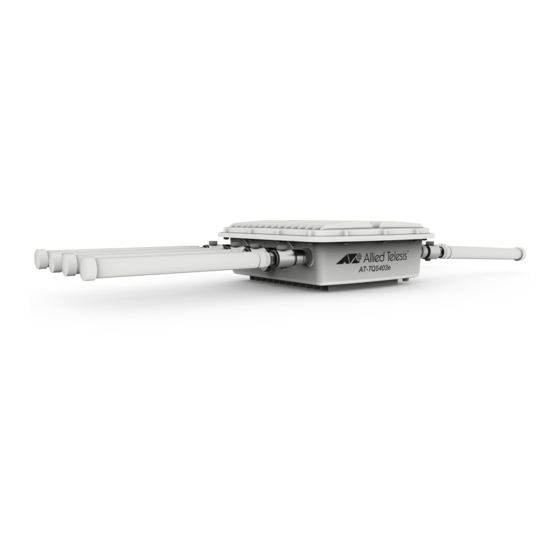
Ethernet 5GHz Antenna LAN and Connector Connector PoE+ Port LEDs and Reset Button Figure 1. Front Panel of the TQ5403e Access Point Antenna The back panel components are illustrated in Figure 2. ® Gore Vent 2.4GHz Antenna 2.4GHz Antenna Connector... -
Page 24: Table 2. Components Of The Access Point
TQ5403e Outdoor Wireless Access Point Installation Guide The components are listed in Table 2. Table 2. Components of the Access Point Component Description Four 5 GHz Antenna N-type female connectors for the 5 GHz antennas Connectors Two 2.4 GHz N-type female connectors for the 2.4 GHz... -
Page 25: Management Tools
You can use SNMPv1 or SNMPv2 to view the parameter settings of the device. The MIB is available from the Allied Telesis web site. For instructions on how to configure the unit for SNMP, refer to Allied Telesis TQ5403 Series Management Software User’s Guide. -
Page 26: Lan Port
TQ5403e Outdoor Wireless Access Point Installation Guide LAN Port The TQ5403e access point has one Ethernet LAN port on the front panel. The port has two functions. The first is to connect the wireless clients to your wired Local Area Network (LAN). The second is to receive power for the product from a PoE+ source device. -
Page 27: Duplex Mode
Chapter 1: Product Description Note The LAN port should be connected to a network device that also adjusts its speed with Auto-Negotiation. If the network device does not support Auto-Negotiation, the LAN port operates at 10 Mbps, which may reduce network performance. Duplex Mode The LAN port can operate in either half- or full-duplex mode at 10 or 100 Mbps, and full-duplex mode at 1000 Mbps. -
Page 28: Leds
TQ5403e Outdoor Wireless Access Point Installation Guide LEDs The access point has three LEDs under the transparent cap on the front panel. Refer to Figure 4. WLAN Power Figure 4. LEDs The LEDs are described in Table 1. Table 3. LEDs... - Page 29 Chapter 1: Product Description Table 3. LEDs (Continued) State Description WLAN Solid Green One or more radios (i.e., Radio1, Radio2, or Radio3) are enabled. All radios are disabled or the access point is powered off. Power Solid Green The power from the PoE+ source device is within the normal operating range.
-
Page 30: Reset Button
TQ5403e Outdoor Wireless Access Point Installation Guide Reset Button The access point has a reset button under the transparent cap on the front panel. Refer to Figure 5. Reset Button Figure 5. Reset Button You can use the reset button to return the parameter settings of the device to their default values. -
Page 31: Cable Specifications
Chapter 1: Product Description Cable Specifications This section has the cable requirements for the Ethernet LAN port. Cable The minimum cable requirements for the LAN port are listed here. Requirements 10 or 100Mbps - Standard TIA/EIA 568-B-compliant Category 3 unshielded cabling. - Page 32 TQ5403e Outdoor Wireless Access Point Installation Guide...
-
Page 33: Chapter 2: Installing The Access Point
Chapter 2 Installing the Access Point This chapter contains the following installation procedures for the TQ5403e access point: “Reviewing Safety Precautions” on page 34 “Unpacking the Access Point” on page 37 “Attaching the Ground Cable to the Access Point” on page 40 ... -
Page 34: Reviewing Safety Precautions
TQ5403e Outdoor Wireless Access Point Installation Guide Reviewing Safety Precautions Please review the following safety precautions before beginning the installation procedures. Note indicates that a translation of the safety statement is available in a PDF document titled Translated Safety Statements on the Allied Telesis website at www.alliedtelesis.com/support. - Page 35 Chapter 2: Installing the Access Point Advertissement Température de fonctionnement. Ce produit est conçu pour une température ambiante maximale de 65 °C. Caution FCC Caution: Any changes or modifications not expressly approved by the party responsible for compliance could void the user's authority to operate this equipment.
- Page 36 TQ5403e Outdoor Wireless Access Point Installation Guide Advertissement Cet équipement doit être installé dans un endroit à accès restreint. Warning Hot Surface, Do Not Touch! - The finned surface on the back of the chassis is a heat sink and can become dangerously hot when the unit is operating.
-
Page 37: Unpacking The Access Point
Chapter 2: Installing the Access Point Unpacking the Access Point To unpack the access point, perform the following procedure: 1. Remove all components from the shipping boxes. Note Store the packaging material in a safe location. You must use the original shipping material if you need to return the unit to Allied Telesis. - Page 38 TQ5403e Outdoor Wireless Access Point Installation Guide Table 4. Components in the Shipping Boxes (Continued) Name Component One Mounting Base Four Sets of Screws, Washers, and Spring Washers for attaching the mounting base to the access point One Pole-mount Bracket...
- Page 39 Six External Surge Protectors with Nuts and Metal and Rubber Washers Ground Note The ground lug on the surge protector is not in use. 3. If any item is missing or damaged, contact your Allied Telesis sales representative for assistance.
-
Page 40: Attaching The Ground Cable To The Access Point
TQ5403e Outdoor Wireless Access Point Installation Guide Attaching the Ground Cable to the Access Point The ground cable protects the device from damage from lightning strikes or electrostatic discharge (ESD). Guidelines Review the following guidelines before attaching the ground cable to the... - Page 41 Chapter 2: Installing the Access Point Ground Posts Figure 6. Ground Posts 3. Insert the screw through the ground lug on the ground wire and secure the wire to the selected ground post on the access point, using a Phillips-head screwdriver. Refer to Figure 7. Figure 7.
- Page 42 TQ5403e Outdoor Wireless Access Point Installation Guide Note The ground wire should be 20AWG or larger and the screw should be 3.5mm or larger. 4. Attach the other end of the ground wire to a circuit breaker, ground rod, or earth ground.
-
Page 43: Connecting An Ethernet Cable To The Access Point
Chapter 2: Installing the Access Point Connecting an Ethernet Cable to the Access Point To connect an Ethernet cable to the access point, perform the following procedure: 1. Place the access point right-side up on a table or desk. 2. Unscrew the cap on the LAN port and remove it from the access point. See Figure 8. - Page 44 TQ5403e Outdoor Wireless Access Point Installation Guide 3. Disassemble the sealing nut, clamping claw, and sealing insert. Refer to Figure 9. Sealing Insert Clamping Claw Sealing Nut Figure 9. Sealing Nut, Clamping Claw, and Sealing Insert 4. Slide the Ethernet LAN cable through the sealing nut and clamping claw.
- Page 45 Chapter 2: Installing the Access Point Groove Figure 11. Installing the Sealing Insert 6. Slide the sealing insert into the clawing clamp. Refer to Figure 12. Figure 12. Inserting the Sealing Insert in the Clawing Clamp 7. Connect the RJ-45 connector on the Ethernet cable into the Ethernet LAN port inside the sealing assembly.
- Page 46 Figure 14. Tightening the Sealing Nut Note The next step powers on the access point by attaching the Ethernet cable to a port on a PoE+ source device. Allied Telesis recommends not performing the step until you have completed all of the installation procedures.
- Page 47 Chapter 2: Installing the Access Point 9. Connect the other end of the Ethernet cable to a port on a PoE+ source device, such as a PoE+ switch.
-
Page 48: Attaching The Antennas To The Access Point
TQ5403e Outdoor Wireless Access Point Installation Guide Attaching the Antennas to the Access Point To install the antennas, perform the following procedure: Note You must install 5GHz antennas to 5GHz antenna connectors and 2.4GHz antennas to 2.4GHz antenna connectors. 1. Remove the blind caps covering the antenna connectors. - Page 49 Chapter 2: Installing the Access Point 4. Install the metal and rubber washers, in that order, on the surge protector. Figure 17. Installing the Metal and Rubber Washers on the Surge Protector 5. Screw an antenna onto the surge protector. Refer to Figure 18. Figure 18.
- Page 50 TQ5403e Outdoor Wireless Access Point Installation Guide 6. Tighten the nut against the antenna to secure the antenna. Refer to Figure 19. Figure 19. Tightening the Nut to Secure the Antenna 7. Repeat this procedure to install the remaining antennas. See Figure...
-
Page 51: Installing The Access Point On A Wall
Chapter 2: Installing the Access Point Installing the Access Point on a Wall This section contains the procedures for installing the TQ5403e access point on a wall. Guidelines Review the following guidelines before installing the access point on a wall: Attach the ground cable to the access point before attaching the ... -
Page 52: What To Prepare For Wall Installation
TQ5403e Outdoor Wireless Access Point Installation Guide The mounting base can be installed in a vertical or horizontal position. See Figure 22. Figure 22. Two Orientations of the Mounting Base What to Prepare You need the following items to install the access point on a wall:... - Page 53 Chapter 2: Installing the Access Point 2. Hold the mounting base on the wall at the desired location for the access point and mark the four mounting base holes with a pencil. See Figure 23. Note The mounting base can be in a vertical or horizontal position. see Figure 22 on page 52.
- Page 54 TQ5403e Outdoor Wireless Access Point Installation Guide Note Attach the ground cable to the access point before attaching the mounting base. See “Attaching the Ground Cable to the Access Point” on page 40. Correct Order of Washers Screw Spring Washer Washer Figure 24.
- Page 55 Chapter 2: Installing the Access Point Figure 25. Attaching the Access Point to the Wall...
-
Page 56: Installing The Access Point On A Pole
TQ5403e Outdoor Wireless Access Point Installation Guide Installing the Access Point on a Pole The TQ5403e access point can be mounted on a pole using either the U-bolts and pole-mount bracket or the pole straps and mounting base. See Figure 26. -
Page 57: Vertical Pole And Horizontal Pole
Chapter 2: Installing the Access Point Table 5. Pole Sizes and Angle Adjustability Angle Method Pole Diameter Range Adjustable U-bolts Φ35mm to 55mm with Pole-mount Bracket Pole Straps Φ80mm to 100mm with Mounting Base Another difference of two methods is whether the angle of the access point is adjustable. -
Page 58: Guidelines For Pole Installation
TQ5403e Outdoor Wireless Access Point Installation Guide Guidelines for Review the following guidelines before installing the access point on a pole: Pole Installation The U-bolts can hold the pole whose diameter is from 35mm to 55mm. The pole straps can hold the pole whose diameter is from 80mm to ... -
Page 59: Pole Installation Using The U-Bolts And Pole-Mount Bracket
Using the Pole Straps and Mounting Base” on page 62. What to Prepare You need the following items to install the access point on a pole using the U-bolts and pole mount bracket: for Pole Installation Using TQ5403e access point the U-Bolts and Pole mount bracket Pole-Mount Four sets of screws, spring washers, and washers for the pole ... - Page 60 TQ5403e Outdoor Wireless Access Point Installation Guide Figure 28. Attaching the Pole-Mount Bracket to the Pole 3. Attach the access point to the pole-mount bracket with the screws using a Phillips-head screwdriver. See Figure 29 on page 61. Note Figure 28 shows how to attach the pole mount bracket to a vertical pole as an example.
-
Page 61: Adjusting The Position Upwards Or Downwards
Chapter 2: Installing the Access Point Figure 29. Attaching the Access Point to the Pole-Mount Brackets Adjusting the To adjust the angle of the access point upwards or downwards, perform the following procedure: Position Upwards or Downwards 1. Loose the two bolts located on the sides of the pole mount brackets using an adjustable wrench or a 10mm socket and ratchet. -
Page 62: Pole Installation Using The Pole Straps And Mounting Base
TQ5403e Outdoor Wireless Access Point Installation Guide Pole Installation Using the Pole Straps and Mounting Base To use the pole straps and mounting base to install the access point, the pole diameter must be from 80mm to 100mm. Note For the pole installation using the U-bolts and pole-mount bracket, see “Pole Installation Using the U-Bolts and Pole-Mount Bracket”... - Page 63 Chapter 2: Installing the Access Point 3. Thread one pole strap through the holes marked 1 to attach to the mounting base. Repeat the threading for the other pole strap. See Figure 30. Figure 30. Threading the Pole Straps Note Figure 30 shows how to install the access point to a vertical pole.
- Page 64 TQ5403e Outdoor Wireless Access Point Installation Guide Figure 31. Securing the Access Point to the Pole Using the Pole Straps 5. Place the tip of the pole strap into the other end of the strap where the screw placed. 6. Tighten the screw with a Phillips-head screwdriver to tighten the pole strap until the access point is attached to the pole securely.
-
Page 65: Starting The Initial Management Session On The Access Point
Chapter 2: Installing the Access Point Starting the Initial Management Session on the Access Point The wireless access point firmware includes a DHCP client. The default setting for the client is enabled. When you power on the access point for the first time, it queries the subnet on the LAN port for a DHCP server. - Page 66 TQ5403e Outdoor Wireless Access Point Installation Guide Figure 32. Login Window 4. Enter “manager” for the username and “friend” for the password. The username and password are case-sensitive.
-
Page 67: Setting The Country Setting
Chapter 2: Installing the Access Point Setting the Country Setting You should set the country setting during the initial management session of the access point to ensure that the device operates in compliance with the codes and regulations of your region or country. Note The non-US model of this product has a country code setting that must be set during the initial management session of the unit. - Page 68 Note This procedure does not require clicking the Save & Apply button. Allied Telesis recommends rebooting the access point after changing the country settings. To reboot the unit, either power off on the unit or continue with these steps: 4.
-
Page 69: Appendix A: Technical Specifications And Statements
Dimensions (W x D x H) 257 mm x 227 mm x 90 mm (10.1 in. x 8.9 in. x 3.5 in.) Weight of the device with antennas 4.0 kg (8.8 lb.) Power Specifications Table 7. TQ5403e Maximum Power Consumption AT-TQ5403e 15.8 watts... -
Page 70: Environmental Specifications
Le présent émetteur radio [3336D-TQ5403E] a été approuvé par Innovation, Sciences et Développement économique Canada pour fonctionner avec les types d'antenne énumérés ci dessous et ayant un gain admissible maximal. -
Page 71: Lan Port
TQ5403e Outdoor Wireless Access Point Installation Guide LAN Port Table 11. LAN Port Specifications Connector RJ45 Standards IEEE 802.3 (10Base-T) IEEE 802.3u (100Base-TX) IEEE 802.3ab (1000Base-T) PoE standard IEEE 802.3at (class 4) Figure 34 illustrates the pin layout of the LAN port. -
Page 72: Table 13. Mdi-X Pin Signals (10Base-T Or 100Base-Tx)
Appendix A: Technical Specifications and Statements Table 13 lists the pin signals for the MDI-X configuration at 10 or 100 Mbps. Table 13. MDI-X Pin Signals (10Base-T or 100Base-TX) Signal Table 14 lists the pin signals when the LAN port is operating at 1000 Mbps. -
Page 73: Safety And Electromagnetic Emissions Certifications
TQ5403e Outdoor Wireless Access Point Installation Guide Safety and Electromagnetic Emissions Certifications Table 15. Safety and Electromagnetic Emissions Certificates Standard RoHs compliant Compliance European Union RoHS (Directive 2011/65/EU of the European Parliament and of the Council of 8 June 2011 on the restriction of the use of certain hazardous substances in electrical and electronic equipment.) -
Page 74: Operation Frequency Information
Appendix A: Technical Specifications and Statements Operation Frequency Information Table 16. Operation Frequency 2.4GHz 5150~5250GHz 5250~5350GHz 5470~5725GHz 5725~5850GHz Indoor Outdoor Indoor Outdoor Indoor Outdoor Indoor Outdoor Indoor Outdoor √ √ √ √ √ √ √ √ √ √ √ √ √... -
Page 75: Ic Statements
TQ5403e Outdoor Wireless Access Point Installation Guide IC Statements This device contains license-exempt transmitter(s)/receiver(s) that comply with Innovation, Science and Economic Development Canada’s license- exempt RSS(s). Operation is subject to the following two conditions: (1) This device may not cause interference. -
Page 76: Avertissement
Appendix A: Technical Specifications and Statements Avertissement Le guide d’utilisation des dispositifs pour réseaux locaux doit inclure des instructions précises sur les restrictions susmentionnées, notamment: (i) les dispositifs fonctionnant dans la bande 5150-5250 MHz sont réservés uniquement pour une utilisation à l’intérieur afin de réduire les risques de brouillage préjudiciable aux systèmes de satellites mobiles utilisant les mêmes canaux;... -
Page 77: Europe - Eu Declaration Of Conformity
TQ5403e Outdoor Wireless Access Point Installation Guide Europe - EU Declaration of Conformity Hereby, Allied Telesis declares that the radio equipment type [AT-TQ5403e] is in compliance with Directive 2014/53/EU. Operating The operating frequencies and maximum transmission power levels for wireless devices operated in the EU are listed below:... - Page 78 Appendix A: Technical Specifications and Statements...
-
Page 79: Appendix B: Radiation Patterns
Appendix B Radiation Patterns This appendix contains the following sections: “2.4GHz Antennas” on page 80 “5GHz Antennas” on page 82 Figure 35. Axes of the Antennas... -
Page 80: 2.4Ghz Antennas
Appendix B: Radiation Patterns 2.4GHz Antennas X-Z Plane (E-total) - Page 81 TQ5403e Outdoor Wireless Access Point Installation Guide X-Y Plane (E-total)
-
Page 82: 5Ghz Antennas
Appendix B: Radiation Patterns 5GHz Antennas X-Z Plane (E-total) - Page 83 TQ5403e Outdoor Wireless Access Point Installation Guide X-Y Plane (E-total)
- Page 84 Appendix B: Radiation Patterns...
Need help?
Do you have a question about the TQ5403e and is the answer not in the manual?
Questions and answers