Sign In
Upload
Download
Table of Contents
Contents
Add to my manuals
Delete from my manuals
Share
URL of this page:
HTML Link:
Bookmark this page
Add
Manual will be automatically added to "My Manuals"
Print this page
×
Bookmark added
×
Added to my manuals
Manuals
Brands
Allied Telesis Manuals
Wireless Access Point
TQ1402
Installation manual
Allied Telesis TQ1402 Installation Manual
802.11ac wave 2 wireless access points with 2.4ghz and 5ghz radios
Hide thumbs
1
2
3
4
5
6
7
8
Table Of Contents
9
10
11
12
13
14
15
16
17
18
19
20
21
22
23
24
25
26
27
28
29
30
31
32
33
34
35
36
37
38
39
40
41
42
43
44
45
46
47
48
49
50
51
52
53
54
55
56
57
58
59
60
61
62
63
64
65
66
67
68
69
70
71
72
page
of
72
Go
/
72
Contents
Table of Contents
Bookmarks
Table of Contents
Table of Contents
Preface
Safety Symbols Used in this Document
Contacting Allied Telesis
Chapter 1: Product Description
Features
Hardware Components
Management Tools
Web Browser
Vista Manager EX and AWC Plug-In
Snmpv1 and V2C
LAN Port
Power over Ethernet (Poe)
Connector Type
Speed
Duplex Mode
Automatic MDIX Detection
Cable Requirements
Maximum Distance
Port Pinouts
DC Connector and On/Off Button for an AC/DC Power Adapter
On/Off Button
Leds
Table 1. LED Status Information
Reset Button
Chapter 2: Installing the Wireless Access Point
Reviewing Safety Precautions
Unpacking the Shipping Box
Table 2. Shipping Box Components
Reviewing Installation Guidelines
Installing the Access Point on a Table
Overview to Installing the Access Point on a Wall or Ceiling
Pre-Fitting the Mounting Bracket on the Access Point
Installing the Mounting Bracket on a Wall or Ceiling
Connecting an Ethernet Cable to the LAN Port
Connecting the AC/DC Power Adapter
Attaching the Access Point to the Mounting Bracket
Installing an Anti-Theft Device
Starting the First Management Session
Appendix A: Technical Specifications
Physical Specifications
Environmental Specifications
Table 3. Physical Specifications
Table 4. Environmental Specifications
Power Specifications
Input Power Specifications
AC/DC Power Adapter Specifications
Table 5. Input Power Specifications
Table 6. External Power Supply Specifications
Poe Power Requirements
Table 7. Poe Power Requirements
LAN Port Specifications and Pinouts
Port Specifications
Cable Specifications
Port Pinouts
Table 8. LAN Port Specifications
Table 9. MDI Pin Signals (10Base-T or 100Base-TX)
Table 10. MDI-X Pin Signals (10Base-T or 100Base-TX)
Table 11. Connector Pinouts (1000Base-T)
Appendix B: Regulatory Statements
Federal Communication Commission Interference Statement
Europe - EU Declaration of Conformity
Operating Frequencies and Maximum Transmission Power Levels
Radiation Exposure Statement
Importer
Appendix C: Radiation Patterns
Ghz Antenna 1
Ghz Antenna 2
5Ghz Antenna 1
5Ghz Antenna 2
Advertisement
Quick Links
Download this manual
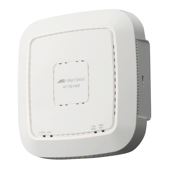
TQ1402 and TQm1402
802.11ac Wave 2 Wireless Access Points
with 2.4GHz and 5GHz Radios
Installation Guide
613-002709 Rev. D
Table of
Contents
Previous
Page
Next
Page
1
2
3
4
5
Advertisement
Table of Contents
Need help?
Do you have a question about the TQ1402 and is the answer not in the manual?
Ask a question
Questions and answers
Related Manuals for Allied Telesis TQ1402
Wireless Access Point Allied Telesis TQ5403 Installation Manual
Enterprise-class 802.11ac wave 2 wireless access points with 2.4ghz and 5ghz radios (82 pages)
Wireless Access Point Allied Telesis TQm1402 Installation Manual
802.11ac wave 2 wireless access points with 2.4ghz and 5ghz radios (72 pages)
Wireless Access Point Allied Telesis TQ5403e Installation Manual
Enterprise-class outdoor wireless access point with ieee802.11a/b/g/n/ac tri-radio (84 pages)
Wireless Access Point Allied Telesis TQ6602 Installation Manual
Enterprise-class 802.11ax indoor wireless access point with 2.4ghz and 5ghz radios (106 pages)
Wireless Access Point Allied Telesis TQ6602 Quick Installation Manual
Wireless access point (4 pages)
Wireless Access Point Allied Telesis TQ6000 Quick Installation Manual
Gen2 wireless access point (4 pages)
Wireless Access Point Allied Telesis TQ6000 GEN2 Series Management Software User Manual
(180 pages)
Wireless Access Point Allied Telesis TQ6702 GEN2 Installation Manual
(84 pages)
Wireless Access Point Allied Telesis TQ6602 GEN2 Quick Installation Manual
(4 pages)
Wireless Access Point Allied Telesis AT-TQ6602 GEN2 Installation Manual
802.11ax dual-radio 5g/2.4ghz 4x4+4x4 wireless ap (70 pages)
Wireless Access Point Allied Telesis AT-TQ6403 GEN2 Installation Manual
Ieee802.11ax tri-radio 5g/5g/2.4ghz 2x2+2x2+2x2+bluetooth low energy wireless ap (68 pages)
Wireless Access Point Allied Telesis AT-TQm6403 GEN2 Quick Installation Manual
(4 pages)
Wireless Access Point Allied Telesis TQ6702e GEN2 Installation Manual
Outdoor wireless access point (94 pages)
Wireless Access Point Allied Telesis TQ6702e GEN2 Quick Installation Manual
(4 pages)
Wireless Access Point Allied Telesis TQ7403 Quick Installation Manual
(4 pages)
Wireless Access Point Allied Telesis TQ2402 GEN2 Installation Manual
Ieee802.1 1ax dual-radio 5g/2.4ghz 2x2+2x2 access point (68 pages)
This manual is also suitable for:
Tqm1402
Table of Contents
Print
Rename the bookmark
Delete bookmark?
Delete from my manuals?
Login
Sign In
OR
Sign in with Facebook
Sign in with Google
Upload manual
Upload from disk
Upload from URL


Need help?
Do you have a question about the TQ1402 and is the answer not in the manual?
Questions and answers