Samson 41-23 Mounting And Operating Instructions
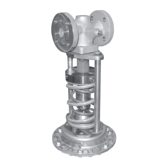
Universal pressure reducing valve self-operated pressure regulators
Hide thumbs
Also See for 41-23:
- Mounting and operation instructions (84 pages) ,
- Mounting and operating instructions (20 pages) ,
- Mounting and operating instructions (2 pages)

Related Manuals for Samson 41-23


Summary of Contents for Samson 41-23
- Page 1 EB 2512 EN Translation of original instructions Type 41-23 Universal Pressure Reducing Valve Self-operated Pressure Regulators Edition June 2020...
- Page 2 Note on these mounting and operating instructions These mounting and operating instructions assist you in mounting and operating the device safely. The instructions are binding for handling SAMSON devices. The images shown in these instructions are for illustration purposes only. The actual product may vary.
-
Page 3: Table Of Contents
Contents Safety instructions and measures ..............1-1 Notes on possible severe personal injury ............1-4 Notes on possible personal injury ..............1-5 Notes on possible property damage .............1-6 Warnings on the regulator ................1-9 Markings on the device ................2-1 Nameplates ....................2-1 Locations of the nameplate ................2-2 Material numbers ..................2-2 2.3.1 Type 2412 Valve ..................2-2... - Page 4 Decommissioning ..................10-1 Removal ....................11-1 11.1 Removing the valve from the pipeline ............11-1 11.2 Removing the actuator from the valve ............11-1 Repairs ....................12-1 12.1 Returning devices to SAMSON ..............12-1 Disposal ....................13-1 Certificates ....................14-1 Annex......................15-1 15.1 Tightening torques ..................15-1 15.2 Lubricant ....................15-1 15.3...
-
Page 5: Safety Instructions And Measures
Therefore, operators must ensure that the regulators are only used in operating conditions that meet the specifications used for sizing the devices at the ordering stage. In case operators intend to use the regulators in other applications or conditions than specified, contact SAMSON. SAMSON does not assume any liability for damage resulting from the failure to use the de- vice for its intended purpose or for damage caused by external forces or any other external factors. Î Refer to the technical data and nameplate for limits and fields of application as well as possible uses. - Page 6 Hazards resulting from the special working conditions at the installation site of the regulator must be identified in a risk assessment and prevented through the corresponding safety in- structions drawn up by the operator. We also recommend checking the hazards posed by the process medium being used (e.g. u GESTIS (CLP) hazardous substance database). Î Observe safety measures for handling the device as well as fire prevention and explosion protection measures. Safety features The Type 41-23 Regulator does not have any special safety features. When relieved of pres- sure, the regulator is opened by the force of the set point springs. EB 2512 EN...
- Page 7 Start-up and shutdown procedures fall within the scope of the operator’s duties and, as such, are not part of these mounting and operating instructions. SAMSON is unable to make any statements about these processes since the operative details (e.g. differential pressures and temperatures) vary in each individual case and are only known to the operator.
-
Page 8: Notes On Possible Severe Personal Injury
Safety instructions and measures Referenced documentation The following documents apply in addition to these mounting and operating instructions: − Mounting and operating instructions for e.g. Acccessories: Compensation chamber u EB 2595 e.g. Type 2 NI Strainer u EB 1015 − Data sheets for Accessories: Compensation chamber · Screw fittings · Control e.g. u T 2595 line connection · Control line Type 2 NI Strainer e.g. -
Page 9: Notes On Possible Personal Injury
Safety instructions and measures 1.2 Notes on possible personal injury WARNING Crush hazard arising from moving parts. The regulator contains moving parts (set point springs), which can injure hands or fin- gers if inserted into the regulator. Î Do not insert hands or fingers between the set point springs while the regulator is in operation. Î Do not insert hands or fingers between the pillars and set point springs while the regulator is in operation. Î Do not insert hands or fingers between the spring plate and crossbeam while the regulator is in operation. Î... -
Page 10: Notes On Possible Property Damage
WARNING Damage to health relating to the REACH regulation. If a SAMSON device contains a substance which is listed as being a substance of very high concern on the candidate list of the REACH regulation, this circumstance is indi- cated on the SAMSON delivery note. - Page 11 Risk of regulator damage due to the use of unsuitable lubricants. The lubricants to be used depend on the regulator material. Unsuitable lubricants may corrode and damage the surface. Î Only use lubricants approved by SAMSON. When in doubt, consult SAMSON. Risk of leakage and regulator damage due to excessively high or low tightening torques.
- Page 12 Î Prevent the formation of ice by taking appropriate precautions (e.g. enclosure, trace heater etc.). The plant operator is responsible for selecting and implementing appropriate precautions. See the 'Installation' section. Note SAMSON's After-sales Service can support you concerning lubricant, tightening torques and tools approved by SAMSON. EB 2512 EN...
-
Page 13: Warnings On The Regulator
Safety instructions and measures 1.4 Warnings on the regulator Warning Meaning of the warning Location on the device Attention ! Warning to indicate that the set point springs are Do not loaded. disassemble the There is a risk of serious head or face injury through the valve without sudden release of the set point springs while unscrewing relieving the... - Page 14 Safety instructions and measures 1-10 EB 2512 EN...
-
Page 15: Markings On The Device
Markings on the device 2 Markings on the device Several nameplates are affixed to the device. The nameplates are used to identify the separa- te regulator components (see Fig. 2-1). 2.1 Nameplates Valve nameplate DIN version ANSI version ANSI version · DIN version Valve type Perm. differential pressure Model number with index 10 Perm. temperature Set point range or spring range Configuration ID 11 Body material Valve size Order number or date Pressure rating Actuator nameplate DIN/ANSI version... -
Page 16: Locations Of The Nameplate
Markings on the device 2.2 Locations of the nameplate 2.3 Material numbers 2.3.1 Type 2412 Valve See the nameplate (11, ANSI/DIN body ma- terial). For more details on the nameplate, see section 2.1. Location of the nameplate on the 2.3.2 Type 2413 Actuator regulator components Specifying the configuration ID, you can con- tact us to find out which material is used. The configuration ID is specified on the namepla- te (3, ANSI/DIN configuration ID). For more details on the nameplate, see section 2.1. Fig. 2-2: Nameplate of the Type 2412 Valve and on the Type 2413 Actuator (diaphragm or bellows) -
Page 17: Design And Principle Of Operation
Î Refer to Fig. 3-1 steam pressure reducing valve or a pressure reducing valve with increased safety (actua- The Type 41-23 Pressure Reducing Valve tor with two diaphragms). consists of a Type 2412 Closing Valve and a Type 2413 Actuator. The valve and actuator The valve closes when the downstream pres- (except for tested regulators) are delivered sure rises. - Page 18 Design and principle of operation Type 2412 Valve Bellows actuator for DN 15 to 50 12.1 Bellows actuator for DN 65 to 100 Type 2413 Diaphragm Actuator Type 2413 Bellows Actuator for 2 to 6, 5 to 10, 10 to 22 and 20 to 28 bar Fig. 3-1: Functional diagram for regulators, DN 32 to 100 with balancing bellows EB 2512 EN...
-
Page 19: Additional Fittings
Any impurities carried along by the process medium may impair the proper functioning Strainers of the regulator. We recommend installing a We recommend installing a SAMSON strainer (e.g. SAMSON Type 2 NI) upstream strainer (2) upstream of the valve. It prevents of the pressure reducing valve (u EB 1015). -
Page 20: Technical Data
− Pressure ratings from PN 16 to 40 The regulator is open when relieved of pres- Note sure. The valve closes when the downstream The Type 41-23 Regulator is not a safety pressure rises. valve. If necessary, a suitable overpressure protection must be installed on site in the Temperature range plant section. - Page 21 Design and principle of operation Noise emission Dimensions and weights SAMSON is unable to make general state- Table 3-5 provides a summary of the dimen- ments about noise emission as it depends on sions and weights. The lengths and heights the regulator version, plant facilities, process in the dimension diagrams are shown on medium and operating conditions.
- Page 22 Design and principle of operation Table 3-2: Max. permissible pressure at actuator Set point ranges Max. perm. pressure above the set point adjusted at the actuator 0.05 to 0.25 bar · 0.1 to 0.6 bar 0.6 bar 0.2 to 1.2 bar 1.3 bar 0.8 to 2.5 bar 2.5 bar 2 to 5 bar 5 bar 4.5 to 10 bar · 8 to 16 bar 10 bar 2 to 6 bar · 5 to 10 bar 6.5 bar 10 to 22 bar 8 bar 20 to 28 bar 2 bar Note The maximum permissible pressure at the actuator depends on the currently adjusted set...
- Page 23 1.5415/1.4301 (stainless steel only) Bellows – 1.4571 In corrosion-resistant version (CrNi steel) Table 3-5: Dimensions in mm and weights in kg Pressure reducing valve Type 41-23 Valve size DN 15 DN 20 DN 25 DN 32 DN 40 DN 50 DN 65 DN 80 DN 100 Length L Height H1 Forged steel – –...
- Page 24 Design and principle of operation Table 3-5: Dimensions in mm and weights in kg Pressure reducing valve Type 41-23 Valve size DN 15 DN 20 DN 25 DN 32 DN 40 DN 50 DN 65 DN 80 DN 100 Standard version with Type 2413 Diaphragm Actuator Height H 3) 0.05 to Actuator ØD = 380 mm, A = 640 cm² 0.25 bar Valve spring force F 1750 N...
- Page 25 Design and principle of operation Table 3-5: Dimensions in mm and weights in kg Pressure reducing valve Type 41-23 Valve size DN 15 DN 20 DN 25 DN 32 DN 40 DN 50 DN 65 DN 80 DN 100 Version with Type 2413 Bellows Actuator Height H 2 to Actuator ØD = 120 mm, A = 62 cm² 6 bar Valve spring force F 4400 N...
- Page 26 Design and principle of operation Dimensional drawings ØD ØD Type 41-23 with diaphragm actuator Type 41-23 with bellows actuator Fig. 3-3: Dimensions 3-10 EB 2512 EN...
-
Page 27: Shipment And On-Site Transport
2. Check the shipment for transportation the inlet and outlet until immediately be- damage. Report any damage to fore installing the valve into the pipeline. SAMSON and the forwarding agent (re- They prevent foreign particles from enter- fer to delivery note). ing the valve. -
Page 28: Transporting And Lifting The Regulator
Shipment and on-site transport 4.3 Transporting and lifting the WARNING regulator Risk of personal injury due to the regulator tipping. Î Observe the regulator's center of gravity. DANGER Î Secure the regulator against tipping over Risk due to suspended loads falling. or turning. -
Page 29: Lifting The Regulator
Shipment and on-site transport 4.3.2 Lifting the regulator 5. After installation in the pipeline, check whether the regulator flanges are bolted To install a large regulator into the pipeline, tight. use lifting equipment (e.g. crane or forklift) 6. Remove slings. to lift it. Lifting instructions Î... -
Page 30: Storing The Valve
Î To keep elastomers in shape and to pre- Î Avoid long storage times. vent cracking, do not bend them or hang Î Contact SAMSON in case of different them up. storage conditions or long storage peri- Î Store elastomers away from lubricants, ods. -
Page 31: Installation
Pipeline routing Î Contact SAMSON if the mounting posi- The inlet and outlet lengths vary depending tion is not as specified above. on the process medium. To ensure that the regulator functions properly, proceed as fol-... - Page 32 Fig. 5-2). Control line kit A control line kit for tapping pressure at the valve body is available as an accessory part from SAMSON. EB 2512 EN...
- Page 33 (16) in addition to the standard with a downward slope. In this case, use a SAMSON screw joint with restriction. “ pipe with screw fittings. EB 2512 EN...
-
Page 34: Preparation For Installation
Installation 5.2 Preparation for installation Proceed as follows: Î Lay out the necessary material and tools Valve and actuator can be assembled before to have them ready during installation or after the valve has been installed in the work. pipeline. We recommend first installing the Î... - Page 35 Installation Table 5-6: Inlet and outlet lengths min. min. a x DN b x DN Control line (e.g. control line kit, see information under ‘Control line’) Inlet length Outlet length State of process Valve conditions Inlet length a Outlet length b medium Ma ≤ 0.3 Vapors...
-
Page 36: Assembly
Risk of regulator damage due to the use of Annex. unsuitable tools. Î Bellows actuator DN 15 to 50 Î Only use tools approved by SAMSON (see Annex). − Remove the crossbeam (8) from the valve. − Insert the actuator stem (11) into the trav- NOTICE el stop cap with cotter pin (20). -
Page 37: Cleaning The Pipeline
Installation 5.3.2 Cleaning the pipeline Î Bellows actuator DN 65 to 100 − Remove the crossbeam (8) from the We recommend additionally flushing the valve. pipeline with installed regulator before start- − Unscrew the pillars (8.1). − Screw the pillars (8.1) into the threaded Î Unscrew the control line (17) from the holes (8.3) of the actuator flange as far valve body. -
Page 38: Testing The Regulator
Î First start up the regulator after mounting Î Wear protective clothing and safety all parts. gloves. SAMSON regulators are delivered ready for WARNING use. To test the regulator functioning before Risk of hearing loss or deafness due to loud start-up or putting back the regulator into noise. -
Page 39: Leak Test
5.4.2 Pressure test Note The plant operator is responsible for performing the pressure test. SAMSON's After-sales Service can support you to plan and perform a pressure test for your plant. EB 2512 EN... -
Page 40: Insulation
Installation 5.5 Insulation To insulate cold systems, we recommend first filling the plant and carefully rinsing it. The regulator must not yet be insulated at this stage. NOTICE Risk of regulator damage due to incorrect insulation. Î Only insulate the regulator up to the ac- tuator for medium temperatures below 0 °C or above 220 °C. 1. -
Page 41: Start-Up
Start-up 6 Start-up process medium and the operating condi- tions. The work described in this section is only to Î Wear hearing protection when working be performed by personnel qualified for the near the valve. assignment accordingly. DANGER WARNING Risk of personal injury due to process me- Crush hazard arising from moving parts. -
Page 42: Starting Up The Plant
Start-up Start-up/putting the valve back into opera- 3. Make sure that the pressure rises simulta- tion neously upstream and downstream of the regulator to avoid damaging the balanc- 1. Depending on the field of application, ing bellows. allow the regulator to cool down or heat up to reach ambient temperature before 6.1.1 Regulation of liquids... -
Page 43: Operation
Operation 7 Operation WARNING Immediately after completing start-up or Crush hazard arising from moving parts. placing the regulator back into operation Î Do not insert hands or fingers between (see the 'Start-up' section), the regulator is the set point springs while the regulator ready for use. - Page 44 Operation An initial adjustment of the set point can also Table 7-1: Set point adjustment · Dimension be made by changing the spring tension un- til the distance x (see Fig. 7-1 and Table 7-1) Set point is reached. Valve size DN range 8 to 16 bar 15 to 25 32 to 50 65 to 100 10 bar x = 89 mm...
-
Page 45: Malfunctions
Î Clean the control line and screw fittings. Î Remove foreign particles. Foreign particles blocking the plug Î When parts are damaged, contact SAMSON's After-sales Service. Î When parts are damaged, contact SAMSON’s Seat and plug are worn or leak. After-sales Service. Downstream pressure Control line blocked Î... - Page 46 Î Remove foreign particles. Foreign particles blocking the plug Î When parts are damaged, contact SAMSON’s After-sales Service. Compensation chamber in the wrong Î Reconnect compensation chamber at a different position or too small (with steam) place or replace it (see Annex).
-
Page 47: Emergency Action
Malfunctions 8.2 Emergency action Note Contact SAMSON’s After-sales Service for The plant operator is responsible for emer- malfunctions not listed in the table. gency action to be taken in the plant. We recommend removing the regulator from The malfunctions listed in section 8.1 are the pipeline before repairing it. - Page 48 EB 2512 EN...
-
Page 49: Servicing
Risk of regulator damage due to the use of become very hot or cold. Risk of burn inju- unsuitable tools. ries. Î Only use tools approved by SAMSON Î Allow components and pipelines to cool (see Annex). down or heat up. - Page 50 The regulator was checked by SAMSON before it left the factory. − Certain test results (seat leakage and leak test) certified by SAMSON lose their validi- ty when the regulator is opened. − The product warranty becomes void if Legend for Fig. 9-1...
- Page 51 Servicing Type 2412 Valve Bellows actuator for DN 15 to 50 12.1 Bellows actuator for DN 65 to 100 Type 2413 Diaphragm Actuator Type 2413 Bellows Actuator for 2 to 6, 5 to 10, 10 to 22 and 20 to 28 bar Fig. 9-1: Functional diagram for regulators, DN 32 to 100 with balancing bellows EB 2512 EN...
-
Page 52: Preparing The Valve For Service Work
Servicing 9.1 Preparing the valve for 9.3 Service work service work Î Before performing any service work, preparations must be made to the regu- 1. Lay out the necessary material and tools lator (see section 9.1). to have them ready for the service work. Î After all service work is completed, check 2. -
Page 53: Replacing The Actuator
Servicing 9.3.1 Replacing the actuator Mounting the actuator 1. Diaphragm actuator DN 15 to 100 Î Refer to Fig. 9-1 Insert the actuator stem (11) through the Removing the actuator hole in the crossbeam (8) into the travel stop cap with cotter pin (20) and fasten 1. Put the regulator out of operation (see the actuator with the nuts (9). -
Page 54: Replacing The Set Point Springs
Servicing 9.3.2 Replacing the set point Mounting the set point springs springs 1. Place the set point springs (7) on the set point adjuster (6). Î Refer to Fig. 9-1 2. Place on the spring plate (7.1) and the Removing the set point springs travel stop cap with cotter pin (20). -
Page 55: Replacing The Seat And Plug
Do not exchange the operating diaphragm in an FDA-compliant regulator version. 3. Unscrew the control line (17). SAMSON's After-sales Service can support 4. Unscrew the nuts (9) and remove the ac- you to perform such service work. tuator. 5. Clamp the actuator stem (11) into a suit- able fixture. Mark the side of the actua-... -
Page 56: Ordering Spare Parts And Operating Supplies
1. Place a new operating diaphragm (12) onto the diaphragm plate (13) (ensuring Contact your nearest SAMSON subsidiary the pressurized side is facing in the cor- or SAMSON's After-sales Service for infor- rect direction) and tighten the diaphragm mation on spare parts, lubricants and tools. plate nut (14). Observe the tightening torques specified in the the Annex. -
Page 57: Decommissioning
Decommissioning 10 Decommissioning WARNING The work described in this section is only to Risk of personal injury due to pressurized be performed by personnel qualified for the components and process medium escaping assignment accordingly. under pressure. Î Do not loosen the control line while the valve is pressurized. DANGER Risk of bursting due to incorrect opening of pressurized equipment or components. - Page 58 Decommissioning To decommission the regulator for service WARNING WARNING work or disassembly, proceed as follows: Risk of personal injury due to residual pro- 1. Close the shut-off valve (1) on the up- cess medium in the regulator. stream side of the regulator. While working on the regulator, residual 2.
-
Page 59: Removal
Removal 11 Removal Before removing the valve, make sure the fol- lowing conditions are met: The work described in this section is only to − The control valve is put out of operation be performed by personnel qualified for the (see the 'Decommissioning' section). assignment accordingly. 11.1 Removing the valve from WARNING the pipeline Risk of burn injuries due to hot or cold com- ponents and pipeline. - Page 60 11-2 EB 2512 EN...
-
Page 61: Repairs
Î Do not perform any repair work on your from our website at own. u www.samsongroup.com > Service Î Contact SAMSON's After-sales Service & Support > After-sales Service. for repair work. After checking your registration, we will send you a return merchandise authori- zation (RMA). - Page 62 12-2 EB 2512 EN...
-
Page 63: Disposal
Disposal 13 Disposal Î Observe local, national and internation- al refuse regulations. Î Do not dispose of components, lubricants and hazardous substances together with your household waste. EB 2512 EN 13-1... - Page 64 13-2 EB 2512 EN...
-
Page 65: Certificates
The declarations of conformity are included on the next pages: − Declaration of conformity in compliance with Pressure Equipment Directive 2014/68/EU on page 14-2. − Declaration of conformity in compliance with Machinery Directive for Type 41-23 Regulator on page 14-4. − Declaration of incorporation in compli- ance with Machinery Directive 2006/42/EC for the Type 2412 Valve with other actuators other than the Type 2413 Actuator on page 14-5. - Page 66 Modul H/Module H, Nr./No. / N° CE-0062-PED-H-SAM 001-16-DEU-rev-A SAMSON erklärt in alleiniger Verantwortung für folgende Produkte:/For the following products, SAMSON hereby declares under its sole responsibility: Ventile für Druck-, Differenzdruck-, Temperatur- und Volumenstromregler/Valves for pressure, temperature, flowregulators and differential pressure regulators Typ 2336, 2373, 2375, 44-1B, 44-2, 44-3, 44-4, 44-6B, 44-9, 45-1, 45-2, 45-3, 45-4, 45-6, (Erz.-Nr.
- Page 67 Modul H/Module H, Nr./No. / N° CE-0062-PED-H-SAM 001-16-DEU-rev-A SAMSON erklärt in alleiniger Verantwortung für folgende Produkte:/For the following products, SAMSON hereby declares under its sole responsibility: Ventile für Druck- Differenzdruck-, Volumenstrom- und Temperaturregler/Valves for pressure, differential pressure, volume flow and temperature regulators 2333 (Erz.-Nr./Model No.
- Page 68 14-4 EB 2512 EN...
- Page 69 EB 2512 EN 14-5...
- Page 70 14-6 EB 2512 EN...
-
Page 71: Annex
– 40 to 640 cm² Control line connection (16) – 40 to 640 cm² 15.2 Lubricant 15.4 Accessories SAMSON's After-sales Service can support Table 15-1: Assignment of compensation you concerning lubricants and sealants ap- chamber (18) to regulator, with item no. proved by SAMSON. Item number Type 2413 Actuator... -
Page 72: Spare Parts
Annex 15.5 Spare parts Version (September 2012 onwards) Lock washer Bellows Hex nut Bellows assembly Crossbeam 101, 102 Diaphragm case Coupling nut Screw plug Balancing screw Diaphragm stem Seat Plug Diaphragm plate 17.1 Pre-stage of plug Diaphragm washer Operating diaphragm 17.2 Seal Hex bolt Body 112 - 114 Hex nut Guide cap Guide (DN 32 to 100) Washer... - Page 73 Annex 25/26 EB 2512 EN 15-3...
-
Page 74: After-Sales Service
E-mail address You can reach our after-sales service at aftersalesservice@samson.de. Addresses of SAMSON AG and its subsid- iaries The addresses of SAMSON, its subsidiaries, representatives and service facilities world- wide can be found on our website (u www.samson.de) or in all SAMSON product catalogs. Required specifications Please submit the following details: −... - Page 78 EB 2512 EN SAMSON AKTIENGESELLSCHAFT Weismüllerstraße 3 · 60314 Frankfurt am Main, Germany Phone: +49 69 4009-0 · Fax: +49 69 4009-1507 samson@samson.de · www.samson.de...
Need help?
Do you have a question about the 41-23 and is the answer not in the manual?
Questions and answers