Table of Contents

Related Manuals for Winmate IP32S


Summary of Contents for Winmate IP32S
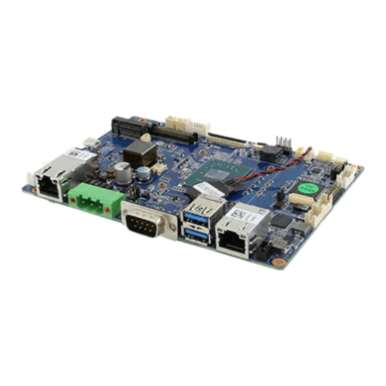
- Page 1 3.5” SBC Intel® Pentium® N4200 (2M Cache, up to 2.5 GHz) IP32S User Manual Document Version 1.0 Board Version V100 Document Part No. 91711110101M Please read this instructions before operating the device and retain them for future reference.
-
Page 2: Table Of Contents
IP32S 3.5" SBC User Manual Contents PREFACE .................................... 4 ABOUT THIS USER MANUAL .............................. 7 CHAPTER 1: GENERAL INFORMATION ..........................8 1.1 I ................................... 9 NTRODUCTION 1.2 F ................................... 9 EATURES 1.3 H ..............................10 ARDWARE PECIFICATIONS 1.4 F ..............................11... - Page 3 Preface 4.5 TXE D ..............................68 RIVER NSTALLATION 4.5 W ..........................70 ATCHDOG RIVER NSTALLATION CHAPTER 5: TECHNICAL SUPPORT ........................... 74 5.1 T ................................75 ECHNICAL UPPORT 5.2 D ..................................75 RIVERS 5.3 S (SDK)............................ 75 OFTWARE EVELOPMENT...
-
Page 4: Preface
IP32S 3.5" SBC User Manual Preface Copyright Notice No part of this document may be reproduced, copied, translated, or transmitted in any form or by any means, electronic or mechanical, for any purpose, without the prior written permission of the original manufacturer. - Page 5 Preface You need to prepare the following information before you call: Product serial number Peripheral attachments Software (OS, version, application software, etc.) Detailed problem description The exact wording of any error messages In addition, free technical support is available from our engineers every business day. We are always ready to give advice on application requirements or specific information on the installation and operation of any of our products.
- Page 6 IP32S 3.5" SBC User Manual Safety and Warranty Please read these safety instructions carefully. Please keep this user manual for later reference. Please disconnect this equipment from any AC outlet before cleaning. Do not use liquid or spray detergents for cleaning. Use a damp cloth.
-
Page 7: About This User Manual
About This User Manual About This User Manual This User Manual provides information about using the IP32S 3.5" SBC. The documentation set for the IP32S 3.5" SBC provides information for specific user needs, and includes: IP32S 3.5" SBC User Manual – contains detailed description on how to use the motherboard, its components and features. -
Page 8: Chapter 1: General Information
Chapter 1: General Information Chapter 1: General Information This chapter includes the IP32S 3.5" SBC background information. Introduction Features Motherboard Specifications Functional Description Physical Description... -
Page 9: Introduction
Pentium® N4200 Apollo Lake processor 1.10 GHz; up to 2.50 GHz with turbo boost technology and Intel® SOC chipset. The IP32S 3.5" SBC supports up to 8 GB of DDR3L SO-DIMM 1600 / 1866 MHz system memory. High performance platform delivers the performance and high scalability cutting-edge embedded computing application. -
Page 10: Hardware Specifications
IP32S 3.5" SBC User Manual 1.3 Hardware Specifications Model Name IP32S 3.5" SBC System Specifications Intel® Pentium® N4200 (2M Cache, up to 2.5 GHz) Chipset Intel® SOC System Memory 1 x DDR3L 1866 MHz SO-DIMM Slot, Max. 8 GB BIOS... -
Page 11: Functional Description
Operating Temperature -20°C ~ 60°C Storage Temperature -30°C ~ 70°C Operating Humidity 30% ~ 90%, non-condensing Power Management Power Input +12V DC Packing List Standard IP32S 3.5" Single Board Computer IP32S Manual & Driver DVD 1.4 Functional Description Function block (V100) -
Page 12: Dimensions
IP32S 3.5" SBC User Manual 1.5 Dimensions Board Dimensions (V100) -
Page 13: Chapter 2: Hardware Installation
Chapter 2: Hardware Installation Chapter 2: Hardware Installation This chapter provides information on how to use jumpers and connectors on the IP32S 3.5" SBC. 2.1 Motherboard Components 2.2 Memory Module Installation 2.3 I/O Equipment Installation 2.4 Jumper Settings 2.5 Motherboard Connectors... -
Page 14: Motherboard Components
IP32S 3.5" SBC User Manual 2.1 Motherboard Components 2.1.1 Key Component Location PCB Top Layer (Top View) PCB Bottom Layer (Top View) -
Page 15: Memory Module (So-Dimm) Installation
2.3.3 HDMI The IP32S 3.5" SBC has one HDMI port that can be connected to an external LCD monitor. Use HDMI cable to connect to an external LCD monitor, and connect the power cable to the outlet. The HDMI connector is a standard 19-pin HDMI connector. -
Page 16: Usb Port
IP32S 3.5" SBC User Manual systems. The Ethernet ports provide two standard RJ-45 jacks, one of those supports PoE function. 2.3.5 USB Port Eight USB devices (four with pin headers) may be connected to the system though an adapter cable. - Page 17 Chapter 2: Hardware Installation USB2, USB3 Internal USB 2.0 2x4 wafer, pitch 2.0mm AUDIO1 Line in/Line out/ Mic in 2x6 wafer, pitch 2.0mm PANEL1 OSD Membrane Control 2x5 wafer, pitch 2.0mm DIDO1 GPIO 2x7 wafer, pitch 2.0mm +5V output 1x2 wafer, pitch 2.0 mm RTC Battery 2P wafer, pitch 1.25 mm 2.4.1.1 J1: Power DC Jack...
- Page 18 IP32S 3.5" SBC User Manual 2.4.1.5 LAN1: Gigabit Ethernet Pin № Signal Name MDI0+ MDI0- MDI1+ MDI1- MDI2+ MDI2- MDI3+ MDI3- 2.4.1.6 LAN2: Gigabit Ethernet with PoE Pin № Signal Name TRDT3 TRD3- TRD3+ TRD2+ TRD2- TRDT2 TRDT4 TRD4+ TRD4-...
- Page 19 Chapter 2: Hardware Installation 2.4.1.7 USB1: USB 3.0 Pin № Pin № Signal Name Signal Name +5VUSB3.0 +5VUSB3.0 U2DN0 U2DN1 U2DP0 U2DP1 USB_GND USB_GND U3RXDN1 U3RXDN2 U3RXDP1 U3RXDP2 USB_GND USB_GND U3TXDN1 U3TXDN2 U3TXDP1 U3TXDP2 2.4.1.8 HDMI1: HDMI Pin № Pin № Signal Name Signal Name HDMI_HPD1...
- Page 20 IP32S 3.5" SBC User Manual 2.4.1.11 CN3: Right-Speaker out Pin № Signal Name OUT + OUT - 2.4.1.12 CN5: NGFF KEY B for SSD Pin № Pin № Signal Name Signal Name +3.3V +3.3V SATA0_DEVSLP_R...
- Page 21 Chapter 2: Hardware Installation Pin № Pin № Signal Name Signal Name SMB_CLK_SSD SMB_DATA_SSD +3.3V +3.3V +3.3V 2.4.1.13 CN6: NGFF KEY E Slot for Wi-Fi, WWAN Card Pin № Pin № Signal Name Signal Name +3.3V USB+ +3.3V USB-...
- Page 22 IP32S 3.5" SBC User Manual Pin № Pin № Signal Name Signal Name PCIE3_TXP1 PCIE3_TXN1 PCIE3_RXP1 PCIE3_RXN1 CLK_PCIE_SLOT3_P CLK_PCIE_SLOT3_N NGFF_WIFI_SUSCLK WIFI_RST# CLKREQ_WIFI# BT_EN PCIE_WAKE# WIFI_EN_R SMB_DATA_WIFI SMB_CLK_WIFI +3.3V +3.3V 2.4.1.14 CN8: USB for Touch 10.1” Pin № Signal Name Ground _N3...
- Page 23 Chapter 2: Hardware Installation 2.4.1.15 CN10, CN12: Light Bar LED Indicator Pin № Signal Name VCC (5V) Red LED Greed LED Blue LED 2.4.1.16 CN11: UART for RFID Pin № Signal Name Ground 2.4.1.17 CN15: MCU Debug Port 2.4.1.18 CN16: RS232 Pin №...
- Page 24 IP32S 3.5" SBC User Manual 2.4.1.21 CON2: Backlight Power Pin № Signal Name 12V or 5V 12V or 5V 12V or 5V Ground Control Pin Ground BLON 2.4.1.22 CON3: LVDS Pin № Pin № Signal Name Signal Name TXO3+ TXE3+...
- Page 25 Chapter 2: Hardware Installation 2.4.1.23 LVDS1: LVDS Pin № Pin № Signal Name Signal Name LCDVDD TXE0- LCDVDD TXE0+ LCDVDD TXE1- TXE1+ TXE2- TXE2+ TXEC- TXEC+ TXE3- TXE3+ TXO0- TXO0+ TXO1- TXO1+ TXO2- TXO2+ TXOC- TXOC+ TXO3- TXO3+ 2.4.1.24 USB2, USB3 : Internal USB 2.0 Pin №...
- Page 26 IP32S 3.5" SBC User Manual 2.4.1.25 AUDIO1: Line in/Line out/ Mic in Pin № Pin № Signal Name Signal Name AZ_FOUT_R AZ_FOUT_L +V5S AUGND LINE1_R LINE1_L MIC1_R MIC1_L AUGND Font_SENSE Mic_SENSE Line_SENSE 2.4.1.26 OD3: OSD Membrane Control Pin № Pin №...
-
Page 27: Chapter 3: Insyde H20 Bios Setup
Chapter 3: Insyde H20 BIOS Setup Chapter 3: Insyde H20 BIOS Setup This chapter describes the different settings available in the INSYDE BIOS that comes with the board. This chapter offers information on the Award BIOS installation utility. 4.1 How and When to Use BIOS Setup 4.2 BIOS Functions 4.3 Using Recovery Wizard to Restore Computer 4.4 How to Enable Watchdog... -
Page 28: How And When To Use Bios Setup
IP32S 3.5" SBC User Manual 3.1 How and When to Use BIOS Setup To enter the BIOS setup, you need to connect an external USB keyboard, external monitor and press Del key when the prompt appears on the screen during start up. The prompt screen shows only few seconds so need press Del key quickly. -
Page 29: Bios Functions
Chapter 3: Insyde H20 BIOS Setup 3.2 BIOS Functions 3.2.1 Main Menu The Main menu displays the basic information about yoursystem including BIOS version, processor RC version, system language, time, and date. When you enter BIOS setup, the first menu that appears on the screen is the main menu.It contains the system information including BIOS version, processor RC version, system language, time, and date. -
Page 30: Advanced
IP32S 3.5" SBC User Manual 3.2.2 Advanced Select the Advanced Tab from the setup menu to enter the advanced BIOS setup screen. You can select any of the items on the left frame of the screen to go to the sub menu for the item, such as CPU Configuration. - Page 31 Chapter 3: Insyde H20 BIOS Setup 3.2.2.1 Boot Configuration BIOS Setting Description Setting Option Effect OS Selection OS Selection Enter Opens submenu...
- Page 32 IP32S 3.5" SBC User Manual 3.2.2.2 Uncore Configuration...
- Page 33 Chapter 3: Insyde H20 BIOS Setup BIOS Setting Description Setting Option Effect WBT Hook WBT Hook Configuration Enabled/ Disabled Enable/ Disabled Configuration WBT Hook RC6 (Render Check to enable render Enabled/ Disabled Enable/ Disabled Standby) standby support, R6C should RC6 (Render RC6 (Render be enabled if S0ix is enabled.
- Page 34 IP32S 3.5" SBC User Manual 3.2.2.3 South Cluster Configuration BIOS Setting Description Setting Option Effect PCI Express PCI Express Enter Opens submenu Configuration Configuration settings. SATA Drives SATA Drives settings. Enter Opens submenu USB Configuration USB Configuration Enter Opens submenu settings.
- Page 35 Chapter 3: Insyde H20 BIOS Setup 3.2.2.3.1 PCI Express Configuration BIOS Setting Description Setting Effect Option PCI Express PCI Express Clock Gating Enabled/ Enable/ Disable PCI Express Clock Gating Enable/ Disable for each Disabled Clock Gating for each root port root port Peer Memory Enable Peer Memory...
- Page 36 IP32S 3.5" SBC User Manual...
- Page 37 Chapter 3: Insyde H20 BIOS Setup 3.2.2.3.2 Chipset-SATA Controller Configuration BIOS Setting Description Setting Option Effect Chipset SATA Chipset SATA Controller. Enabled/ Disabled Enable or Disable the Settings. Chipset SATA Controller. SATA Mode Select SATA Mode. AHCI AHCI for a system using Selection When you activate AHCI SATA disks (non-RAID)
- Page 38 IP32S 3.5" SBC User Manual 3.2.2.3.3 USB Pre-Port Control...
- Page 39 Chapter 3: Insyde H20 BIOS Setup BIOS Setting Description Setting Option Effect USB Per-Port USB Per-Port Control a Enabled/ Control each of the USB ports Control settings. Disabled (0~7) enable/ disable. XDCI Support Allows you to enable or Enabled/ Enable or Disable XDCI Support disable xDCI (USB OTG Disabled Device).
- Page 40 IP32S 3.5" SBC User Manual 3.2.2.3.5 TXE Configuration BIOS Setting Description Setting Option Effect Target TPM Select Target TPM dTPM Select Target TPM Device Device Device...
- Page 41 Chapter 3: Insyde H20 BIOS Setup 3.2.2.3.6Thermal Configuration Parameters BIOS Setting Description Setting Option Effect Critical Trip This value controls the 125 C Select the point in which the Point temperature of the OS will shut down the ACPI Critical Trip Point system.
- Page 42 IP32S 3.5" SBC User Manual 3.2.2.3.7 Serial Port BIOS Setting Description Setting Option Effect Serial Port A~ D Configure serial port Enabled User configuration settings. Disabled No configuration Auto EFI/ OS chooses configuration WDT count mode and Enabled/ Enable or disable WDT.
- Page 43 Chapter 3: Insyde H20 BIOS Setup 3.2.2.3.8 WTD BIOS Setting Description Setting Option Effect WDT count mode and Enabled/ Enable or disable WDT. counter settings. Disabled Select WDT settings.
- Page 44 IP32S 3.5" SBC User Manual BIOS Setting Description Setting Option Effect WDT Count WDT Count Mode Default [Minute] Set the timeout counter to Mode [Minute]. Counter The timeout counter. Default [0] Please Set the timeout counter to [5]. change to [5]...
- Page 45 Chapter 3: Insyde H20 BIOS Setup 3.2.2.3.9 Hardware Monitor 3.2.2.3.10 General Purpose Group 0 Input/ Output...
- Page 46 IP32S 3.5" SBC User Manual BIOS Setting Description Setting Option Effect Internal Internal Resistance Push Pull User can pull internal Resistance settings resistance push-pull Open Drain User can pull internal resistance open drain Input/ Output Select Input/ Output Input Set the GPI0 pin input...
-
Page 47: Security
Chapter 3: Insyde H20 BIOS Setup 3.2.3.Security BIOS Setting Description Setting Option Effect TrEE Protocol TrEE Protocol 1.0 or 1.1 Version Version: 1.0 or 1.1 TPM Availability TPM Availability Available TPM Operation TPM Operation No operation Clear TPM Clear TPM Set Supervisor Set Supervisor Custom-setting... -
Page 48: Power
IP32S 3.5" SBC User Manual 3.2.4 Power BIOS Setting Description Setting Option Effect CPU Configuration Enter Opens sub-menu Configuration settings... - Page 49 Chapter 3: Insyde H20 BIOS Setup 3.2.4.1 CPU Configuration BIOS Setting Description Setting Option Effect VTX2 VTX2 mode support Enabled/ Disabled To enable or disable settings VTX2 mode support VT-d VT-d support settings Enabled/ Disabled To enable or disable VT-d support TM1 support settings Enabled/ Disabled To enable or disable...
- Page 50 IP32S 3.5" SBC User Manual 3.2.4.2 System Power Options BIOS Setting Description Setting Option Effect Intel Intel SpeedStep settings Enabled/ Disabled Allows more than two SpeedStep frequency ranges to be supported Intel Turbo Intel Turbo Boost Max Performance Enabled-Enables the logical...
-
Page 51: Boot
Chapter 3: Insyde H20 BIOS Setup 3.2.5 Boot BIOS Setting Description Setting Option Effect Boot Type Select Boot Type Dual/ Legacy/ Select boot type to Dual type, UEFI Legacy type or UEFI type. Quick Boot Quick Boot settings Enabled/ Disabled Enable or disable Quick Boot Quiet Boot Quiet Boot settings... - Page 52 IP32S 3.5" SBC User Manual 3.2.5.1 Boot Type Order 3.2.5.2 Hard Disk Drive...
-
Page 53: Exit
Chapter 3: Insyde H20 BIOS Setup 3.2.5.3 Others 3.2.6 Exit... - Page 54 IP32S 3.5" SBC User Manual BIOS Setting Description Setting Option Effect Exit Saving Exit Saving Setting Enter Exit system and save your Setting changes Exit Saving Exit Saving Setting Enter Save change without exit Setting Exit Saving Exit Saving Setting...
-
Page 55: Using Recovery Wizard To Restore Computer
Chapter 3: Insyde H20 BIOS Setup 3.3 Using Recovery Wizard to Restore Computer Note: Before starting the recovery process, make sure to backup all user data. The data will be lost after the recovery process. Important: Before starting the recovery process, remove any expansion card. To enable quick one-key recovery procedure: 1. -
Page 56: How To Enable Watchdog
3.4 How to Enable Watchdog To enable Watchdog, you need to download Winmate Watchdog utility. Find more information on Watchdog in “Watchdog Guide” that you can download from Winmate Download Center or File Share. Refer to the User Manual for more details. - Page 57 Chapter 3: Insyde H20 BIOS Setup 3. In Watchdog utility window set countdown time and periodically feed time, or disable watchdog. Example: Every 10 min watchdog will monitor the system, in case any error occurs the system will restart automatically when the countdown time reaches 0.
-
Page 58: Chapter 4: Driver Installation
IP32S 3.5" SBC User Manual Chapter 4: Driver Installation This chapter contains driver installation instructions for the IP32S 3.5" SBC. 3.1 Chipset Driver Installation 3.2 Graphics Driver Installation 3.3 Audio Driver Installation 3.4 LAN Driver Installation 3.6 TXE Driver Installation... -
Page 59: Chipset Driver
Chapter 4: Driver Installation 4.1 Chipset Driver Follow instructions below to install Chipset driver. 1. Open the Driver CD (included in the package) and select Chipset driver. When installation window will pop up, select Next. - Page 60 IP32S 3.5" SBC User Manual 2. Select Accept to agree with the terms of license agreement. 3. Check the ReadMe file information, select Install to continue.
- Page 61 Chapter 4: Driver Installation 4. Wait for the driver to be installed. When installation completed, select Finish to exit installation window.
-
Page 62: Graphics Driver
IP32S 3.5" SBC User Manual 4.2 Graphics Driver Follow instructions below to install Graphic driver. 1. Open the Driver CD (included in the package) and select Graphics driver. When installation window will pop up, select Next. 2. Select Accept to agree with the terms of license agreement. - Page 63 Chapter 4: Driver Installation 3. Check the ReadMe file information, select Next to continue. 4. Wait for the driver to be installed.
-
Page 64: Audio Driver
IP32S 3.5" SBC User Manual 5. When installation is completed, select “Yes, I want to restart this computer now”, and click Finish. 4.3 Audio Driver Follow instructions below to install Audio Driver. 1. Open the Driver CD (included in the package) and select Audio driver. When installation window will... -
Page 65: Lan Driver
Chapter 4: Driver Installation 1. When installation is completed, select “Yes, I want to restart this computer now”, and click Finish. 4.4 LAN Driver Follow instructions below to install LAN driver. 1. Open the Driver CD (included in the package) and select LAN driver. When installation window will pop up, select Next to continue. - Page 66 IP32S 3.5" SBC User Manual 2. Read the license agreement, and then select Next. 3. System displays the installed packages, select Next.
- Page 67 Chapter 4: Driver Installation 4. Confirm the installation, select Install to start the installation. 5. When installation is completed, select Finish to close the window.
-
Page 68: Txe Driver Installation
IP32S 3.5" SBC User Manual 4.5 TXE Driver Installation Follow instructions below to install TXE driver. 2. Open the Driver CD (included in the package) and select TXE driver. When installation window will pop up, select Next to start the installation. - Page 69 Chapter 4: Driver Installation When installation is completed, select Finish to close the window.
-
Page 70: Watchdog Driver Installation
IP32S 3.5" SBC User Manual 4.5 Watchdog Driver Installation For more details about Winmate Watchdog, please download Watchdog Guide from Winmate Downloads Center here. Follow instructions below to install Watchdog driver. 1. Type “cmd” in the run box then the cmd.exe will appear in programs. - Page 71 Chapter 4: Driver Installation Installation. 5. Wait for installation to complete. When installation is complete, press any key to close. 6. Open the Driver CD (included in the package) and select Watchdog AP.
- Page 72 IP32S 3.5" SBC User Manual 7. Select Next. 8. The installed storage location is displayed, select Next to continue. 9. Select Next to start the installation.
- Page 73 Chapter 4: Driver Installation 10. When installation is completed, select Finish to close the window.
-
Page 74: Chapter 5: Technical Support
IP32S 3.5" SBC User Manual Chapter 5: Technical Support This chapter contains directory to technical support. 5.1 Drivers 5.2 Software Development Kit (SDK) -
Page 75: Technical Support
Free technical support is available from our engineers every business day. We are always ready to give advice on application requirements or specific information on the installation and operation of any of our products. If any problem occurs immediately contact us. 5.2 Drivers The list of drivers available for IP32S 3.5" SBC: Item Driver Chipset Driver... - Page 76 Winmate Inc. 9F, No.111-6, Shing-De Rd., San-Chung District, New Taipei City 24158, Taiwan, R.O.C www.winmate.com Copyright © Winmate Inc. All rights reserved.
Need help?
Do you have a question about the IP32S and is the answer not in the manual?
Questions and answers