Table of Contents
Advertisement
Quick Links
Advertisement
Table of Contents

Related Manuals for Winmate IP70


Summary of Contents for Winmate IP70
- Page 1 Mini-ITX SBC Intel® Pentium® N4200 Apollo Lake Processor 1.10 GHz (up to 2.50 GHz with turbo boost technology) IP70 User Manual Document Version 1.0 Board Version V100 Document Part No. 91711110101L Please read this instructions before operating the device and retain them for future reference.
-
Page 2: Table Of Contents
IP70 Mini-ITX SBC User Manual Contents PREFACE .................................... 4 ABOUT THIS USER MANUAL .............................. 6 CHAPTER 1: GENERAL INFORMATION ..........................7 1.1 I ................................... 8 NTRODUCTION 1.2 F ................................... 8 EATURES 1.3 H ..............................9 ARDWARE PECIFICATIONS 1.4 F ..............................10... - Page 3 Preface 3.2.5 Boot ..................................54 3.2.6 Exit ..................................55 3.3 U ......................... 57 SING ECOVERY IZARD TO ESTORE OMPUTER 3.4 H .............................. 58 OW TO NABLE ATCHDOG CHAPTER 4: DRIVER INSTALLATION ..........................60 4.1 C ................................61 HIPSET RIVER 4.2 G ................................
-
Page 4: Preface
IP70 Mini-ITX SBC User Manual Preface Copyright Notice No part of this document may be reproduced, copied, translated, or transmitted in any form or by any means, electronic or mechanical, for any purpose, without the prior written permission of the original manufacturer. - Page 5 Preface You need to prepare the following information before you call: Product serial number Peripheral attachments Software (OS, version, application software, etc.) Detailed problem description The exact wording of any error messages In addition, free technical support is available from our engineers every business day. We are always ready to give advice on application requirements or specific information on the installation and operation of any of our products.
-
Page 6: About This User Manual
The equipment has been dropped and damaged. The equipment has obvious signs of breakage. About This User Manual This User Manual provides information about using the IP70 Mini-ITX SBC. The documentation set for the IP70 Mini-ITX SBC provides information for specific user needs, and includes: ... -
Page 7: Chapter 1: General Information
Chapter 1: General Information Chapter 1: General Information This chapter includes the IP70 Mini-ITX SBC background information. Introduction Features Motherboard Specifications Functional Description Physical Description... -
Page 8: Introduction
IP70 Mini-ITX SBC User Manual 1.1 Introduction Thank you for choosing the IP70 Mini-ITX SBC. The IP70 Mini-ITX SBC is powered by Intel ® Pentium® N4200 Apollo Lake processor 1.10 GHz; up to 2.50 GHz with turbo boost technology and Intel® SOC chipset. -
Page 9: Hardware Specifications
Chapter 1: General Information 1.3 Hardware Specifications Model Name IP70 Mini-ITX SBC System Specifications Intel® Pentium® N4200 Apollo Lake Processor 1.10 GHz, up to 2.50 GHz with turbo boost technology Chipset Intel® SOC System Memory 2 × DDR3L 1866 MHz SO-DIMM ( max. 8GB ) -
Page 10: Functional Description
IP70 Mini-ITX SBC User Manual Model Name IP70 Mini-ITX SBC Expansions Slot 1 x M.2 Slot (for SSD) 1 x M.2 Slot (for Wi-Fi) 1 x PCIE2.0 (x1) slot (Optional) Mechanical Specifications Dimensions 170 x 170 mm Operating Temperature -20°C ~ 60°C Storage Temperature -40°C ~ 70°C... -
Page 11: Dimensions
Chapter 1: General Information 1.5 Dimensions Board Dimensions (V100) -
Page 12: Chapter 2: Hardware Installation
IP70 Mini-ITX SBC User Manual Chapter 2: Hardware Installation This chapter provides information on how to use jumpers and connectors on the IP70 Mini-ITX SBC. 2.1 Motherboard Components 2.2 Memory Module Installation 2.3 I/O Equipment Installation 2.4 Jumper Settings 2.5 Motherboard Connectors... -
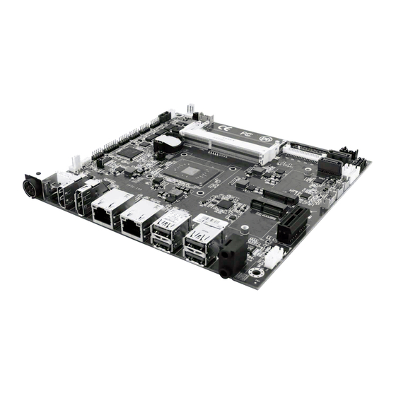
Page 13: Motherboard Components
Chapter 2: Hardware Installation 2.1 Motherboard Components 2.1.1 Component Side 2.1.2 Key Component Location PCB Top Layer (Top View) -
Page 14: Jumper Location
IP70 Mini-ITX SBC User Manual PCB Bottom Layer (Top View) 2.1.3 Jumper Location... -
Page 15: Memory Module (So-Dimm) Installation
2.3.3 HDMI The IP70 Mini-ITX SBC has one HDMI port that can be connected to an external LCD monitor. Use HDMI cable to connect to an external LCD monitor, and connect the power cable to the outlet. The HDMI connector is a standard 19-pin HDMI connector. -
Page 16: Ethernet Interface
The Display Port connector is a standard 20-pin DP connector. 2.3.5 Ethernet Interface The IP70 Mini-ITX SBC is equipped with Intel® I210AT Gigabit-LAN Controller + I219LM Gigabit-LAN PHY which is fully compliant with the PCI 10/100/1000 Mbps Ethernet protocol compatible. It is supported by major network operating systems. -
Page 17: Control Backlight Power On/Off
Chapter 2: Hardware Installation Jumper List: Label Function Note JP1, JP2, JP11 Control Backlight Power On/Off Header 3*1 JP4, JP5, JP6, JP7 Backlight Brightness Control Header 3*1 CON1 Control Panel Power Header 2*3 JP8, JP9 OSD Option Header 3*1 JP10 PWM Control Header 3*1 JP12, JP13... -
Page 18: Control Panel Power
IP70 Mini-ITX SBC User Manual 2.4.3 Control Panel Power CON1 Location Header Type Description Setting Function 1-2 (Default) +3.3V CON1 Header 2*3 Panel Power SEL +12V 2.4.4 OSD Option Location Header Type Description Setting Function 4 Key OSD Header 3*1... -
Page 19: Mainboard Connectors
Chapter 2: Hardware Installation 2.5 Mainboard Connectors 2.5.1 Internal Front Side Connectors Label Function Note ATX_PWR_2X2 2x2 Power Wafer RTC Battery Socket DisplayPort Connector Audio Jack Left Speaker Right Speaker M.2-E WIFI/BT M.2-B SSD Power Jack 4P DIN 12V Pin Power Wafer CN10 Power Output Wafer 12V Yellow Wafer... - Page 20 DC_GND +12V +12V 2.5.1.2 BT1: RTC Battery Socket Pin № Signal Name BACKUP_VBAT 2.5.1.3 CN2: DisplayPort Connector IP70 Mini-ITX SBC has one Display Port 1.2 connector. Pin № Pin № Signal Name Signal Name Lane 0+ Lane 0- Lane 1+...
- Page 21 Chapter 2: Hardware Installation 2.5.1.7 CN6: M.2-E WIFI/BT Pin № Pin № Signal Name Signal Name +3.3V USB+ +3.3V USB- PCIE_TXP0 PCIE_TXN0 PCIE_RXP0 PCIE_RXN0 CLK_PCIE_SLOT_P CLK_PCIE_SLOT_N NGFF_WIFI_SUSCLK WIFI_RST# CLKREQ_WIFI# BT_EN PCIE_WAKE# WIFI_EN_R SMB_DATA_WIFI SMB_CLK_WIFI NGFF_SMB_ALERT...
- Page 22 IP70 Mini-ITX SBC User Manual +3.3V +3.3V 2.5.1.8 CN7: M.2-B SSD Pin № Pin № Signal Name Signal Name +3.3V +3.3V PERN3 PERP3 SSD_LED PETN3 PETN2 PETP2 PERN1 PERP1 PETN1 PETP1 SATA1_DEVSLP PERP0/SATA_RX+ PERN0/SATA_RX- PETN0/SATA_TX- PETP0/SATA_TX+ SSD_SATA_PERST# SSD_SATA_CLKREQ#...
- Page 23 SIM_DET SSD_SATA_SUS_CLK PCIE_SSD_PEDET +3.3V +3.3V +3.3V 2.5.1.9 CN8: Power Jack 4P DIN 12V The DC power input for the IP70 Mini-ITX SBC allows a voltage input of 12V DC. Pin № Pin № Signal Name Signal Name 12VDC 12VDC 2.5.1.10 CN9: Pin Power Wafer Pin №...
- Page 24 IP70 Mini-ITX SBC User Manual 2.5.1.12 CN11, CN12: Power Output Wafer 5V 2.5.1.13: CN13: ISP Port Pin № Signal Name +3.3V C2DAT C2CK RESET# 2.5.1.14 COM1, COM2, COM3, COM4: COM Port Header Pin № Pin № Signal Name Signal Name...
- Page 25 Chapter 2: Hardware Installation PCIE_REFCLK+ PCIE_REFCLK- PCIE_TX+ PCIE_TX- PCIE_RX+ PEIC_RX- CLKREQ_PCIEX1# 2.5.1.16 CON2: Backlight Power/Control Pin № Signal Name BKL_PWR BKL_PWR BKL_PWR BRIGHT BLON_5V 2.5.1.17 CPU_FAN1: CPU FAN 2.5.1.18 DEBUG1: Debug Port 80 Pin № Pin № Signal Name Signal Name LPC_AD0 +3.3V LPC_AD1...
- Page 26 2.5.1.22 LAN1, LAN2: RJ45 IP70 Mini-ITX SBC has two Ethernet connectors located on the front. Ethernet ports provide a standard RJ45 10/100/1000 Mbps jack connector with LED indicators on the front side to show its Active/ Link status and Speed status.
- Page 27 Chapter 2: Hardware Installation 2.5.1.23 LVDS1:LVDS Connector Pin № Pin № Signal Name Signal Name LCDVDD LVDS0_TX0_N LCDVDD LVDS0_TX0_P LCDVDD LVDS0_TX1_N LVDS0_TX1_P LVDS0_TX2_N LVDS0_TX2_P LVDS0_CLK_N LVDS0_CLK_P LVDS0_TX3_N LVDS0_TX3_P LVDS1_TX0_N LVDS1_TX0_P LVDS1_TX1_N LVDS1_TX1_P LVDS1_TX2_N LVDS1_TX2_P LVDS1_CLK_N LVDS1_CLK_P LVDS1_TX3_N LVDS1_TX3_P 2.5.1.24 PANEL1: Front Panel Pin №...
- Page 28 IP70 Mini-ITX SBC User Manual 2.5.1.25 PJ1: eDP Connector Pin № Signal Name BKL_PWR BKL_PWR BKL_PWR BKL_PWR BRIGHT BLON_5V eDP_HPD eDP_AUX- eDP_AUX+ eDP_TX3_D- eDP_TX3_D+ eDP_TX2_D- eDP_TX2_D+ eDP_TX1_D- eDP_TX1_D+ eDP_TX0_D- eDP_TX0_D+ LCDVDD LCDVDD...
- Page 29 Chapter 2: Hardware Installation 2.5.1.26 SATA1, SATA2: SATA Power Pin № Signal Name SATA_TX- SATA_TX+ SATA_RX- SATA_RX+ 2.5.1.27 SW1: Clear CMOS + Reset Button Pin № Signal Name RESET RTC CLR CMOS 2.5.1.28 SYS_FAN1: System FAN 2.5.1.29 VGA1: VGA Wafer Pin №...
- Page 30 IP70 Mini-ITX SBC User Manual 2.5.1.31 USB3, USB4: 2 x USB 3.0 Type A Pin № Pin № Signal Name Signal Name USB_D- USB_D+ STDA_SSRX- STDA_SSRX+ GND_DRAIN STDA_SSTX- STDA_SSTX+...
-
Page 31: Chapter 3: Insyde H20 Bios Setup
Chapter 3: Insyde H20 BIOS Setup Chapter 3: Insyde H20 BIOS Setup This chapter describes the different settings available in the INSYDE BIOS that comes with the board. This chapter offers information on the Award BIOS installation utility. 4.1 How and When to Use BIOS Setup 4.2 BIOS Functions 4.3 Using Recovery Wizard to Restore Computer 4.4 How to Enable Watchdog... -
Page 32: How And When To Use Bios Setup
IP70 Mini-ITX SBC User Manual 3.1 How and When to Use BIOS Setup To enter the BIOS setup, you need to connect an external USB keyboard, external monitor and press Del key when the prompt appears on the screen during start up. The prompt screen shows only few seconds so need press Del key quickly. -
Page 33: Bios Functions
Chapter 3: Insyde H20 BIOS Setup 3.2 BIOS Functions 3.2.1 Main Menu The Main menu displays the basic information about yoursystem including BIOS version, processor RC version, system language, time, and date. When you enter BIOS setup, the first menu that appears on the screen is the main menu.It contains the system information including BIOS version, processor RC version, system language, time, and date. -
Page 34: Advanced
IP70 Mini-ITX SBC User Manual 3.2.2 Advanced Select the Advanced Tab from the setup menu to enter the advanced BIOS setup screen. You can select any of the items on the left frame of the screen to go to the sub menu for the item, such as CPU Configuration. - Page 35 Chapter 3: Insyde H20 BIOS Setup BIOS Setting Description Setting Option Effect Boot Configures Boot setting. Enter Opens submenu Configuration Uncore Configures Uncore setting. Enter Opens submenu Configuration South Cluster Configures South Cluster setting. Enter Opens submenu Configuration Security Configures Security setting. Enter Opens submenu Configuration...
- Page 36 IP70 Mini-ITX SBC User Manual 3.2.2.2 Uncore Configuration...
- Page 37 Chapter 3: Insyde H20 BIOS Setup BIOS Setting Description Setting Option Effect RC6 (Render Check to enable render Enable/ Disabled Enable/ Disabled Standby) standby support, R6C should RC6 (Render RC6 (Render be enabled if S0ix is enabled. Standby) Standby) GTT Size Select the GTT size.
- Page 38 IP70 Mini-ITX SBC User Manual 3.2.2.3 South Cluster Configuration BIOS Setting Description Setting Option Effect HD-Audio HD-Audio Enter Opens submenu Configuration Configuration settings. PCI Express PCI Express Enter Opens submenu Configuration Configuration settings. SATA Drives SATA Drives settings. Enter Opens submenu...
- Page 39 Chapter 3: Insyde H20 BIOS Setup 3.2.2.3.1 HD-Audio Configuration BIOS Setting Description Setting Option Effect HD-Audio Support HD-Audio Support settings Enabled/ Disabled Enable/ Disable HD Audio support HD-Audio DSP HD-Audio DSP settings Enabled/ Disabled Enable/ Disable HD-Audio DSP HD-Audio CSME HD-Audio CSME Memory HD-Audio CSME Memory Memory Transfer...
- Page 40 IP70 Mini-ITX SBC User Manual Display Link Select Display Link 96 MHz Select Display Link Frequency Frequency settings. Frequency settings. 3.2.2.3.2 PCIE Express Configuration BIOS Setting Description Setting Effect Option PCI Express PCI Express Clock Gating Enabled/ Enable/ Disable PCI Express...
- Page 41 Chapter 3: Insyde H20 BIOS Setup 3.2.2.3.3 Chipset-SATA Controller Configuration BIOS Setting Description Setting Option Effect Chipset SATA Chipset SATA Controller. Enabled/ Disabled Enable or Disable the Chipset Settings. SATA Controller. SATA Mode Select SATA Mode. AHCI AHCI for a system using SATA Selection When you activate AHCI disks (non-RAID)
- Page 42 IP70 Mini-ITX SBC User Manual 3.2.2.3.4 USB Pre-Port Control BIOS Setting Description Setting Option Effect USB Per-Port USB Per-Port Control a Enabled/ Disabled Control each of the USB Control settings. ports (0~7) enable/ disable. XDCI Support Allows you to enable or...
- Page 43 Chapter 3: Insyde H20 BIOS Setup 3.2.2.3.5 Miscellaneous Control BIOS Setting Description Setting Option Effect High Precision High Precision Enabled/ Disabled Enable or Disable the High Timer Timer settings Precision Event Timer 8254 Clock Gating 8254 Clock Gating Enabled/ Disabled Enable or Disable 8254 Clock Gating State After G3...
- Page 44 IP70 Mini-ITX SBC User Manual 3.2.2.3.6 TXE Configuration BIOS Setting Description Setting Option Effect Target TPM Select Target TPM dTPM Select Target TPM Device Device Device...
- Page 45 Chapter 3: Insyde H20 BIOS Setup 3.2.2.3.7 Thermal Configuration Parameters BIOS Setting Description Setting Option Effect Critical Trip This value controls the 125 C Select the point in which the Point temperature of the OS will shut down the ACPI Critical Trip Point system.
- Page 46 IP70 Mini-ITX SBC User Manual 3.2.2.3.8 Serial Port BIOS Setting Description Setting Option Effect Serial Port A~ D Configure serial port Enabled User configuration settings. Disabled No configuration Auto EFI/ OS chooses configuration WDT count mode and Enabled/ Disabled Enable or disable WDT.
- Page 47 Chapter 3: Insyde H20 BIOS Setup Serial Port Mode Settings: RS232, RS485, RS422 3.2.2.3.9 Hardware Monitor...
- Page 48 IP70 Mini-ITX SBC User Manual BIOS Setting Description Setting Option Effect Fan Mode Select Fan Manual Select Manual to manually configure fan’s operating speed. Mode Linear In Linear settings the voltage applied to the fan is variable. Stage Stage fan control mode.
- Page 49 Chapter 3: Insyde H20 BIOS Setup 3.2.2.3.11 H2oUve Setup BIOS Setting Description Setting Option Effect H2oUve H2oUve Support Enabled/ Disabled Enable or Disable interface Support settings for H2oUve tool...
-
Page 50: Security
IP70 Mini-ITX SBC User Manual 3.2.3.Security BIOS Setting Description Setting Option Effect TrEE Protocol TrEE Protocol 1.0 or 1.1 Version Version: 1.0 or 1.1 TPM Availability TPM Availability Available TPM Operation TPM Operation No operation Clear TPM Clear TPM Set Supervisor... -
Page 51: Power
Chapter 3: Insyde H20 BIOS Setup 3.2.4 Power BIOS Setting Description Setting Option Effect CPU Configuration Enter Opens sub-menu Configuration settings Wake on PME Wake on PME settings Disabled/ Enabled Determines the action taken by OS/ Force when the system power is off Enable and a PCI Power Management wake up event... - Page 52 IP70 Mini-ITX SBC User Manual 3.2.4.1 CPU Configuration BIOS Setting Description Setting Option Effect VTX2 VTX2 mode support Enabled/ Disabled To enable or disable settings VTX2 mode support VT-d VT-d support settings Enabled/ Disabled To enable or disable VT-d support...
- Page 53 Chapter 3: Insyde H20 BIOS Setup 3.2.4.2 System Power Options BIOS Setting Description Setting Option Effect Intel Intel SpeedStep settings Enabled/ Disabled Allows more than two SpeedStep frequency ranges to be supported Intel Turbo Intel Turbo Boost Max Performance Enabled-Enables the logical Boost Technology settings processor cores on...
-
Page 54: Boot
IP70 Mini-ITX SBC User Manual 3.2.5 Boot BIOS Setting Description Setting Option Effect Boot Type Select Boot Type Dual/ Legacy/ Select boot type to Dual type, UEFI Legacy type or UEFI type. Quick Boot Quick Boot settings Enabled/ Disabled Enable or disable Quick Boot... -
Page 55: Exit
Chapter 3: Insyde H20 BIOS Setup 3.2.5.1 Boot Type Order 3.2.6 Exit... - Page 56 IP70 Mini-ITX SBC User Manual BIOS Setting Description Setting Option Effect Exit Saving Exit Saving Setting Enter Exit system and save your Setting changes Exit Saving Exit Saving Setting Enter Save change without exit Setting Exit Saving Exit Saving Setting...
-
Page 57: Using Recovery Wizard To Restore Computer
Chapter 3: Insyde H20 BIOS Setup 3.3 Using Recovery Wizard to Restore Computer Note: Before starting the recovery process, make sure to backup all user data. The data will be lost after the recovery process. Important: Before starting the recovery process, remove any expansion card. To enable quick one-key recovery procedure: 1. -
Page 58: How To Enable Watchdog
3.4 How to Enable Watchdog To enable Watchdog, you need to download Winmate Watchdog utility. Find more information on Watchdog in “Watchdog Guide” that you can download from Winmate Download Center or File Share. Refer to the User Manual for more details. - Page 59 Chapter 3: Insyde H20 BIOS Setup 3. In Watchdog utility window set countdown time and periodically feed time, or disable watchdog. Example: Every 10 min watchdog will monitor the system, in case any error occurs the system will restart automatically when the countdown time reaches 0.
-
Page 60: Chapter 4: Driver Installation
IP70 Mini-ITX SBC User Manual Chapter 4: Driver Installation This chapter contains driver installation instructions for the IP70 Mini-ITX SBC. 3.1 Chipset Driver Installation 3.2 Graphics Driver Installation 3.3 Audio Driver Installation 3.4 LAN Driver Installation 3.6 TXE Driver Installation 3.7 Wireless Bluetooth Driver Installation... -
Page 61: Chipset Driver
Chapter 4: Driver Installation 4.1 Chipset Driver Follow instructions below to install Chipset driver. 1. Open the Driver CD (included in the package) and select Chipset driver. - Page 62 IP70 Mini-ITX SBC User Manual 2. Installation window will pop up, select Next. 3. Select Accept to agree with the terms of license agreement.
- Page 63 Chapter 4: Driver Installation 4. Check the ReadMe file information, select Install to continue. 5. Wait for the driver to be installed. When installation completed, select Restart Now to restart your computer.
-
Page 64: Graphics Driver
IP70 Mini-ITX SBC User Manual 4.2 Graphics Driver Follow instructions below to install Graphic driver. 1. Open the Driver CD (included in the package) and select Graphics driver. - Page 65 Chapter 4: Driver Installation 2. Installation window will pop up, select Next. 3. Select Accept to agree with the terms of license agreement.
- Page 66 IP70 Mini-ITX SBC User Manual 4. Check the ReadMe file information, select Next to continue. 5. Wait for the driver to be installed.
-
Page 67: Audio Driver
Chapter 4: Driver Installation 6. When installation is completed, select “Yes, I want to restart this computer now”, and click Finish. 4.3 Audio Driver Follow instructions below to install Audio Driver. 1. Open the Driver CD (included in the package) and select Audio driver. - Page 68 IP70 Mini-ITX SBC User Manual 2. Select Next to start the installation. 3. Select Next to proceed.
-
Page 69: Lan Driver
Chapter 4: Driver Installation 4. When installation is completed, select “Yes, I want to restart this computer now”, and click Finish. 4.4 LAN Driver Follow instructions below to install LAN driver. 1. Open the Driver CD (included in the package) and select LAN driver. 2. - Page 70 IP70 Mini-ITX SBC User Manual 3. Read the license agreement, and then select Next. 4. System displays the installed packages, select Next.
- Page 71 Chapter 4: Driver Installation 5. Confirm the installation, select Install to start the installation. 6. When installation is completed, select Finish to close the window.
-
Page 72: Txe Driver Installation
IP70 Mini-ITX SBC User Manual 4.5 TXE Driver Installation Follow instructions below to install TXE driver. Open the Driver CD (included in the package) and select TXE driver. - Page 73 Chapter 4: Driver Installation Select Next to continue. Read the license agreement, and then select Next.
- Page 74 IP70 Mini-ITX SBC User Manual System displays the installed packages, select Next.
-
Page 75: Wireless Bluetooth Driver
Chapter 4: Driver Installation When installation is completed, select Finish to close the window. 4.5 Wireless Bluetooth Driver Follow instructions below to install Intel AC7265/ AC865/ AC9260 driver. Open the Driver CD (included in the package) and select Intel AC7265/ AC865/ AC9260 driver. - Page 76 IP70 Mini-ITX SBC User Manual Select Next to continue.
- Page 77 Chapter 4: Driver Installation Select Next to continue. Read the license agreement, and then select Next. Choose setup type, and click Next to continue.
- Page 78 IP70 Mini-ITX SBC User Manual Click Install to start installation process.
-
Page 79: Watchdog Driver Installation
Chapter 4: Driver Installation When installation is completed, select Finish to close the window. 4.6 Watchdog Driver Installation For more details about Winmate Watchdog, please download Watchdog Guide from Winmate Downloads Center here. Follow instructions below to install Watchdog driver. - Page 80 IP70 Mini-ITX SBC User Manual 2. Right click on the cmd.exe and click on “Run as administrator” to start 3. Open the Driver CD (included in the package) and select Watchdog driver. 4. When Windows Security dialog appear, select install to continue the Installation.
- Page 81 Chapter 4: Driver Installation 5. Wait for installation to complete. When installation is complete, press any key to close. 6. Open the Driver CD (included in the package) and select Watchdog AP. 7. Select Next.
- Page 82 IP70 Mini-ITX SBC User Manual 8. The installed storage location is displayed, select Next to continue. 9. Select Next to start the installation. 10. When installation is completed, select Finish to close the window.
-
Page 83: Digital Io Driver Installation
Chapter 4: Driver Installation 4.7 Digital IO Driver Installation For more details about Winmate Watchdog, please download Digital IO Guide from Winmate Downloads Center: Follow instructions below to install Digital IO river. 1. Type “cmd” in the run box then the cmd.exe will appear in programs. - Page 84 IP70 Mini-ITX SBC User Manual 6. Open the Driver CD (included in the package) and select Digital IO AP.
-
Page 85: Chapter 5: Technical Support
Chapter 5: Technical Support Chapter 5: Technical Support This chapter contains directory to technical support. 5.1 Drivers 5.2 Software Development Kit (SDK) -
Page 86: Technical Support
Free technical support is available from our engineers every business day. We are always ready to give advice on application requirements or specific information on the installation and operation of any of our products. If any problem occurs immediately contact us. 5.2 Drivers The list of drivers available for IP70 Mini-ITX SBC: Item Driver Chipset Driver... - Page 88 Winmate Inc. 9F, No.111-6, Shing-De Rd., San-Chung District, New Taipei City 24158, Taiwan, R.O.C www.winmate.com Copyright © Winmate Inc. All rights reserved.
Need help?
Do you have a question about the IP70 and is the answer not in the manual?
Questions and answers