Advertisement
Quick Links
GENERAL:
GENERAL:
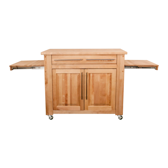
1. You have purchased model 1480DOR.
1. You have purchased model 1480.
2. Should you need assistance or need to replace a damaged or missing part simply give us a call M-F
at 607-652-7321 from 7:30 am - 4:30 pm Eastern and we'll send you the prepaid part via UPS usually
2. Should you need assistance or need to replace a damaged or missing part simply give us a call M-F at
607-652-7321 from 7:30 am - 4:30 pm EST and we'll send you the prepaid part via UPS usually that same day!
that same day! You may also email us: info@catskillcraftsmen.com.
You may also email us info@catskillcraftsmen.com.
3. Read the assembly instructions and the enclosed brochure before beginning assembly. Assembly is
3. Read the assembly instructions and the enclosed brochure before beginning assembly. Assembly is easy
easy if you read and follow the instructions step by step. See our website for assembly tips and videos:
if you read and follow the instructions step by step. See our website for assembly tips and videos:
www.catskillcraftsmen.com
www.catskillcraftsmen.com
4. The only tools needed are a hammer, a small and a medium Phillips head screwdriver and a medium
4. The only tools needed are a hammer and a screwdriver. A power screwdriver is recommended. Where
flat blade screwdriver. A pencil is also needed. A power screwdriver will speed assembly, but is not
possible we have packaged some of the screws in separate labeled packages. A friend is recommended to assist
required. Place a few drops of vegetable oil on the threads of wood screws before screwing into the
with the assembly. Some parts are large and awkward to hold in place.
solid hardwood parts.
5. Glides are sometimes pre-packed with screws. These are not used.
5. Glides are sometimes pre-packed with screws. These are not used.
6. Instructions (left/right, top/bottom) are given as you face an assembled unit.
6. Instructions (left/right, top/bottom) are given as you face an assembled unit.
Assembly Instructions
Assembly Instructions
Model 1480DOR
Model 1480DOR
The Empire Work Center
Empire Island
Advertisement

Subscribe to Our Youtube Channel
Related Manuals for CATSKILL 1480


Summary of Contents for CATSKILL 1480
- Page 1 GENERAL: 1. You have purchased model 1480DOR. 1. You have purchased model 1480. 2. Should you need assistance or need to replace a damaged or missing part simply give us a call M-F at 607-652-7321 from 7:30 am - 4:30 pm Eastern and we’ll send you the prepaid part via UPS usually 2.
-
Page 2: Cabinet Parts
(1) Drawer Bottom-1480 39 3/16” x 22 1/8” x 7/16” 31 9/16” x 21 3/4” x 1/4” (2) Side Panel Inserts-1480 (1) Middle Shelf-1480DOR (Edge Banded) 20 9/16” x 22 11/16” x 1/4” 39 3/16” x 21 7/16” x 7/16”... - Page 3 (4) Cutting Board Glide Support-1480DOR 19” x 3/4” x 3/4” (2) Right Leg-1480DOR (Inside View) 32 1/2” x 4” x 7/8” (Inside View) (4) Cutting Board Side Rail-1480DOR 18” x 1 1/4” x 3/4” (Inside View) (2) Left Leg-1480DOR 32 1/2” x 4” x 7/8” (Inside View) (2) Cutting Board Front-1480DOR 21 3/4”...
- Page 4 HARDWARE Note: Not to scale 1 3/4” Phillips Flat Head Bolt (12) 18” Full Ext Glide Sets (3) MSKRU M5-25 For Handles (16) (Drawer Back & 1/2” Flat Washer (16) Cutting Board Glide Support) 10-24 Hex 1 1/4” Phillips Flat Head #8 Screw (12) Nut (12) (Attaches Cutting Board Side Rails)
- Page 5 TIPS ON HOW THE BASTION FASTENING SYSTEM WORKS 1. The Bastion fastening system consists of a steel post (threaded on one end with a hole through the shaft on the other end); a Barrel Nut (cylindrical barrel-shaped with threaded Illustration Bas. 1 open end &...
- Page 6 STEP 1 Slide Out Cutting Board Assembly - Part 1 2 Pull Out Cutting Board Tops, 2 Cutting Board Fronts, 4 Cutting Board Sides. Lay Pull Out Cutting Board Top on its 2 1/2” #8 Screws back so holes face up. Then attach Counter Sink Up the Cutting Board Front to the top Cutting Board Front...
-
Page 7: Drawer Assembly
STEP 3 Drawer Assembly 2 Drawer Sides, 1 Drawer Back, 1 Drawer Front, 1 Drawer Bottom Attach Drawer Back to Drawer Sides using 1 1/4” #8 scews, then insert Drawer Bottom into slots best side up. Put Bastion Posts into Drawer Front & secure to Drawer Sides using Barrel Nuts & Set Screws. - Page 8 STEP 4 Brace Preparation Insert 3/4” pins into each end of the Top and Bottom Braces and Drawer Glide Supports. OK if Pins are loose. Top Back Brace Top Front Brace Front/Back Bottom Brace (2) Drawer Glide Support Brace (2) Right Leg Left Leg STEP 5...
- Page 9 STEP 6 Back Panel Assembly Front and Back Panel 3/4” Pin Top Back Brace 1 1/2” Pin Assembly A. The Back Panel Assembly consists of a Right and Left Rear Leg, Top Back Brace, Bottom Brace, a Left Door and a Right Door.
-
Page 10: Back Panel Assembly
STEP 7 Attach Magnet Plates STEP 7 Attach Magnet Plates Using 1/2” Phillips Flat Head #4 screws from your Magnet Pack attach the Magnet Plates to the small Using 1/2” Phillips Flat Head #4 screws from your Magnet Pack attach the Magnet Plates to the small pilot holes at the top of the Doors. - Page 11 STEP 8 Insert Caster Sleeves and Cutting Board Glides A. Insert the Caster Sleeves into the holes in the bottom of the Legs and tap in with a hammer until the teeth grabs the wood - don’t pound flat! Repeat for the front assembly. B.
- Page 12 STEP 9 Brace Prep A. When positioned properly the 6 pilot holes in the Glide Support Sticks will be closer to the bottom edge. The Glide will overhang the Glide Support Sticks on the front edge by about an 1/8 of an inch and slightly on the bottom.
- Page 13 Hex Nut 1 3/4 machine screws from back side Illustration 9D TIP: Place a towel or tablecloth (movable) on the table, that will Drawer Glide Supports allow you to rotate the Back Make sure the glides are to the bottom!!! Assembly without scratching the tabletop.
- Page 14 STEP 10 Attach Front Assembly 2 Person Job!! A. Attach the front assembly to the sides using Pins and 1 3/4” Machine Screws/Nuts. B. Insert the castors into the caster sockets. 1 3/4 machine screws Illustration 10A Tip: Don’t try to align all the pins at the same time.
- Page 15 STEP 11 Castors and Shelf Pins A. Upright the unit. B. Insert (10) 1 1/2” pins into the pin holes at the bottom (1 in each leg and 1 in each bottom brace). The Middle Shelf has 3 adjustable heights, determine which height to use and insert the 1 1/2”...
- Page 16 STEP 13 Insert Shelves Slide in the Bottom Shelf and fit it over the Bottom Pins. Then slide in the Middle Shelf (with edge banding) and fit it over the middle set of Pins. STEP 14 Add Drawer and Cutting Boards Slide the Drawer into the front of the cart then slide the Slide Out Cutting Boards into the...
- Page 17 Catskill Craftsmen, Inc. 15 West End Ave. Inc. 15 West End Ave., Stamford, NY 12167-1296 Catskill Craftsmen, Inc. Please make checks payable to Catskill Craftsmen Inc. Stamford, NY 12167-1296 15 West End Ave. 15 West End Ave., Stamford, NY 12167-1296...
Need help?
Do you have a question about the 1480 and is the answer not in the manual?
Questions and answers