Advertisement
Quick Links
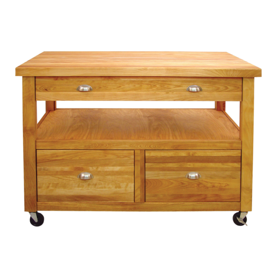
Assembly Instructions
Model 1426
The Americana WorkCenter
GENERAL:
1. You have purchased model 1426.
2. Should you need assistance or need to replace a damaged or missing part simply give us a call M-F at
607-652-7321 from 7:30 am - 4:30 pm EST and we'll send you the prepaid part via UPS usually that same day!
You may also email us info@catskillcraftsmen.com.
3. These units are ready-to-assemble. Catskill uses positive fastening methods suh as wood screws and in some
places hidden Bastion Fasteners. You will need some standard houshold tools: hammer and screwdriver (power
screwdriver is recommended). Where possible, we have packaged some of the screws in seperate labeled pack-
ages. To keep hardware separate after packets are open, we suggest you place each type of screw into separate
containers. Note labels for screws and when they are to be used in assembly in the instructions.
4. Directions (left/right, front/back) are given as facing the front of an assembled upright unit.
5. A friend is reccommended to assist with assembly as this will ease the process. Some of the parts are large
and awkward to hold in place, and extra pair of hands are a huge help.
Advertisement

Related Manuals for CATSKILL 1426


Summary of Contents for CATSKILL 1426
- Page 1 607-652-7321 from 7:30 am - 4:30 pm EST and we’ll send you the prepaid part via UPS usually that same day! You may also email us info@catskillcraftsmen.com. 3. These units are ready-to-assemble. Catskill uses positive fastening methods suh as wood screws and in some places hidden Bastion Fasteners. You will need some standard houshold tools: hammer and screwdriver (power screwdriver is recommended).
-
Page 2: Parts List
(2) Bottom Drawer Right Side (3 sets) 20” Drawer Glide (4) Top/Bottom Side Glide Support Sticks 18” x 8” x 3/4” 18” x 8” x 3/4” Part #: GL-20-1426 19-7/16” x 2” x 3/4” Part #:BDLS1426 Part #:BDRS1426 Part #: TBSGSS1426... - Page 3 CABINET HARDWARE 1 1/4” Phillips Flat Head #8 Screw (12) Bastion Post (34) 5/8” Phillips Flat Head #6 Screw (8) Bastion Bastion Set Screw (34) Barrel Nut (34) 5/8” Phillips Flat Head #5 Screw (12) (Handle Screw) 3/4” Truss Head Machine Screw (8) Handles (4) “L”...
- Page 4 TIPS ON HOW THE BASTION FASTENING SYSTEM WORKS 1. The Bastion fastening system consists of a steel post (threaded on one end with a hole through the shaft on the other end); a Barrel Nut (cylindrical barrel-shaped with threaded Illustration Bas. 1 open end &...
-
Page 5: Back Assembly
STEP 1 BACK ASSEMBLY 1. Begin assembly by laying out all of the pieces and checking against the parts list on the previous pages.Tap Caster sleeves for the caster wheels into the bottom of the legs using a standard hammer. Do not insert wheels yet. -
Page 6: Front Assembly
STEP 2 FRONT ASSEMBLY Tap Caster sleeves into the bottom of the legs. Do Not insert wheels yet. Assemble the Front Assem- bly by laying out the Front Right and Left Legs, Front Center Brace, Front Bottom Brace, Front Verti- cal Brace as well as the necessary Bastions and 3/4”... -
Page 7: Side Panel Assembly
STEP 3 SIDE PANEL ASSEMBLY Lay the Back Assembly on a smooth flat surface as in Illustration 3A. Screw the Bastion Posts into the legs and Back Vertical Brace as shown in the Bastion Fastening Instructions on Page 3. When properly seated, the screwdriver slot in the post ends will beperpendicular to the length of the legs. - Page 8 STEP 4 ATTACHING FRONT ASSEMBLY Upright Back Assembly with Braces, etc. Attached from Step 3. Caster holes in legs should be facing down as shown in Illustration 4A. Attach Bastion Posts and tap in 3/4” Steel Pins into front legs and Front Vertical Brace.
- Page 9 STEP 5 ATTACH DRAWER GLIDES Attach the Cabinet drawer glides for both bottom drawers and the top drawer to the drawer support sticks using the 5/8” #7 screws. Note: refer to the label included with screw pack to make sure the ap- propriate screws are used for this step.
- Page 10 STEP 6 INSERT SHELF Make sure 1” Steel Pins were firmly tapped into place in the pilot holes on each of the center braces in previous steps. Then, take the center shelf and dip it down into the unit, putting one end down near the bottom drawer support stick as shown in Illustration 6A.
- Page 11 STEP 6 ASSEMBLE DRAWERS A. Attach the Drawer Back to the Left and Right Drawer Sides with four 1 ¼” #8 Screws. Make sure the slots that run the length of the Sides are aligned with the slot in the Drawer Back to accept the Drawer Bottom.
- Page 12 STEP 8 ATTACH BUTCHER BLOCK TOP Attach the 4 L-Brackets to the top side braces with 5/8” # 6 screws. Note the orientation of the L-Brackets in Illustration 8A. The single slot side should attach to the Top Side Braces while the slot and hole side should attach to the Butcher Block Top, also using 5/8”...
- Page 13 Visa and Address _____________________________ Mastercard are accepted online. City ________________________________ State ________________ Zip ___________ Catskill Craftsmen, Inc. Please make checks payable to Catskill Craftsmen Inc. 15 West End Ave. 15 West End Ave., Stamford, NY 12167-1296 Stamford, NY 12167-1296...
Need help?
Do you have a question about the 1426 and is the answer not in the manual?
Questions and answers